Abstract
In modern endoscopy, wide field of view and full color are considered necessary for navigating inside the body, inspecting tissue for disease and guiding interventions such as biopsy or surgery. Current flexible endoscope technologies suffer from reduced resolution when device diameter shrinks. Endoscopic procedures today using coherent fiber bundle technology, on the scale of 1 mm, are performed with such poor image quality that the clinician’s vision meets the criteria for legal blindness. Here, we review a new and versatile scanning fiber imaging technology and describe its implementation for ultrathin and flexible endoscopy. This scanning fiber endoscope (SFE) or catheterscope enables high quality, laser-based, video imaging for ultrathin clinical applications while also providing new options for in vivo biological research of subsurface tissue and high resolution fluorescence imaging.
Keywords: medical imaging, optical scanning, endoscopy, endomicroscopy, two-photon microscopy
1. Introduction to ultrathin flexible endoscopes
Medical imaging of internal organs can be categorized into two groups:(1) structure-based imaging, such as x-ray computed tomography (CT),magnetic resonance imaging (MRI), and ultrasound, which typically image at low spatiotemporal resolution (millimeters, seconds); and (2) surface-based imaging using optical endoscope technologies, which image at high spatiotemporal resolution (micrometers, milliseconds). Because endoscopic imaging requires direct visualization of internal organ surfaces, both illumination and detection elements must be ported through an often tortuous anatomical geometry to a region of interest. As such, the accessibility of internal organs is dictated by both the size and rigidity of the endoscope. For many applications, a smaller diameter and flexible endoscope is often preferred for reducing tissue trauma and medication (sedation) to reduce pain experienced by the subject [1].
Conventional flexible endoscopes are approximately the same thickness as a human finger and are primarily designed for high quality color imaging. Relatively wide field of view imaging (>70° FOV) is necessary for navigating the scope within the body, inspecting tissue, diagnosing disease, and guiding surgical interventions. Flexible endoscopy was ushered in by coherent fiberoptic bundles (CFB), which serve as bendable conduits for transmitting light between proximal and distal ends of the endoscope [2]. CFB technology is still in use today, but more modern incarnations often employ a proximal video camera for image capture and subsequent display on a video monitor. Most flexible endoscopes are comprised of miniature charge-coupled device (CCD) video chips that have been placed at the distal tip of the flexible shaft, though incoherent optical fiber bundles are still used to deliver white light illumination [3]. Though these approaches technically differ, they share a common design feature: every pixel in the video display is associated with an imaging element, be it an optical core in the CFB or sensor element in a miniature video chip.
To accommodate imaging within small vessels, lumens, and ducts within the human body, ultrathin endoscopes have been developed by reducing the overall device diameter. However, ultrathin endoscopes less than 3 mm in diameter suffer from reduced image quality using conventional imaging technology. Typically, the minimum center-to-center spacing of imaging elements is 3 microns, requiring over 3 mm in diameter to produce 1024 line images. Manufacturers offer a wide assortment of CFB sizes and lengths suitable for endoscopic use [4-5]. However, the CFB glass is suited for illumination in the visible to infrared range [6-7], but not for wide field fluorescence imaging using UV excitation [8]. To achieve higher spatial resolution while sacrificing FOV, laser-beam scanning at the proximal end of the CFB is performed in a confocal geometry for fluorescence microscopy, endoscopic microscopy or endomicroscopy [8-11].
Despite the unique advantages offered by CFB endoscopes as a passive device, there are also a number of limitations. The CFB is semi-rigid as the optical fibers are typically fused into a single glass rod. Bending the CFB often leads to core fracture, creating dead pixels in the display. Unintended perforation during a medical procedure is perceived as a serious problem with ultrathin, semi-rigid endoscopes [12] The ability to control shaft rigidity down to extreme flexibility of guidewires and catheters is needed. By matching endoscope mechanical properties to that of the target organ, risk of perforation sub-millimeter diameter scopes can be avoided[13]. Leached CFB technologies contain a non-fused length between distal and proximal ends, and were developed to alleviate durability and flexibility issues. These leached fiber bundles do exhibit some superior mechanical properties, but 2x lower core density than CFB and higher cost deter their acceptance[14].
The most confounding limitation of CFBs is poor image quality due to the restricted number of imaging pixels and a honeycomb effect produced by non-imaging space between optical cores. Both high resolution and wide FOV are not possible (see section 4.2). For example, a standard CFB of 30,000 optical fibers has 3 micron center-to-center spacing across an active area of 0.75 mm resulting in 250 pixels across the FOV. If the distal lens produces an imaging FOV of 75°, then the minimal angle of resolution is roughly 0.3° per pixel. The human eye has a minimum angle of resolution of 1 minute of arc or 1/60° or 0.0167°. Typically the primary legal definition for blindness is 10x lower visual acuity than normal vision (20/200 in USA or 6/60 in Europe, [15], see also http://en.wikipedia.org/wiki/Blindness) which translates to 0.167°. A 1 mm endoscope using a ring of illumination fibers around a standard 30,000 fiber bundle generates images below the limit of legal blindness. Visual acuity can be increased by restricting FOV and magnifying the image, accomplished by changing the lensing. Although sub-cellular resolution is achievable, the microscopic FOV greatly impedes the utility of the endoscope. Again the legal definition of blindness is helpful because the secondary criterion is having a restricted FOV (<20°) even with average visual acuity. These optical and mechanical limitations of CFB devices explain, in large part, why ultrathin flexible endoscopes are only minimally sufficient and not routinely used for medical procedures. Albeit there is great potential for performing less invasive procedures in previously inaccessible regions of the human body if limitations in image quality and endoscope flexibility can be overcome.
In this paper, we review developments in the field of endoscopy and endomicroscopy with comparisons to a new scanning fiber endoscope(SFE) technology we have invented for the purpose of enhancing the performance of ultrathin flexible endoscopes and catheterscopes [1, 16]. The SFE technology produces high-resolution, large FOV images by active scanning of laser light instead of passive imaging from diffuse white-light illumination. Low-power red, green, and blue (RGB) laser light is combined at the proximal end of the SFE and conveyed to the distal end using a singlemode optical fiber in a coaxial configuration. A fiber scanner is located at the scope’s distal tip of the endoscope concentric with the optical axis, which allows diffraction-limited focus through the central part of the lens. When the end of this single optical fiber is held by a small piezoelectric actuator, the cantilevered free end of this optical waveguide can be vibrated near its mechanical resonance. A less than ±0.4 mm in lateral free-end deflection amplitude of the central fiber can project scanned laser illumination to greater than 100°, full cone angle to achieve wide FOV. Detection of the laser light can be realized in various reflection mode geometries. In this paper several modes of light collection are explained (see section 2.4), though emphasis is placed on the non-confocal mode of operation, as this geometry allows for wide FOV and high quality color imaging that is essential to endoscopy.
Following a detailed description of the SFE technology in section 2, unique features are discussed in section 3. Alternative emerging endoscope technologies are compared in section 4 with detailed comparisons of the SFE to conventional CFB and camera-based endoscopes. Specific clinical and research applications of SFE to wide-field imaging and of in vivo fluorescence SFE microscopy are reviewed in section 5. In the latter application, sub-surface functional imaging of the rodent brain is accomplished using the versatile SFE in combination with higher numerical aperture (NA) optics to achieve sub-micrometer lateral resolution. To conclude this review, we examine how this SFE instrumentation can advance clinical endoscopy and biomedical research. It is possible that entirely new concepts will be embraced by the next generation of clinicians who routinely use ultrathin flexible endoscopes for minimally-invasive medical practice.
2. Scanning fiber endoscope (SFE)
The SFE technology has been developed at the University of Washington for the purpose of providing high quality laser-based imaging within an ultrathin and flexible endoscope [16-19]. To our knowledge, the concept of moving an optical fiber to produce a 2D images with confocal sectioning and laser illumination was first proposed for endoscopic applications by Giniunas et al., in 1993 [20]. The major advancement of the SFE is rapid scanning and generation of high quality images using an amplitude-modulated resonating fiber.
2.1. Mechanically resonant fiber scanner
The central component of the SFE technology is a single optical waveguide vibrated at mechanical resonance to scan RGB laser light onto the image plane. The resonant singlemode optical fiber is vibrated laterally using a custom tubular piezoelectric (PZT 5A) actuator in an ultra-compact co-axial design (Figure 1). The lateral vibratory motion can be modeled as a cylindrical, base-excited cantilever with fixed-free boundary conditions as in Equation 1 [21]. The cantilever diameter is either the standard 125 micron or 80 micron cladding diameter of a fused silica, singlemode optical fiber [1]. Different specialty fibers can be used for particular applications, such as hollow-core photonics crystal fibers (PCFs) for distortion-free femtosecond pulse delivery [18, 22-23]. Cantilever length is the extension of the fiber beyond the distal end of the tubular piezoelectric actuator (tube piezo), which determines the resonant frequency. By electrically driving the tube piezo near the scanning fiber’s fundamental mode of lateral resonance, the fiber tip motion experiences a mechanical gain of 100 to 200 [24]. Shaping the cross-sectional axial profile along this fiberoptic cantilever from a cylinder to a more complex shape by acid etching can produce additional gains of 30% to 100% [25-26]. Nonetheless, the general co-axial design of the SFE (Figure 1) is ideal for the compact and simple design of ultrathin endoscopes.
| Equation 1 |
Figure 1.
Functional diagram of the SFE with the scanning illumination fiber moving in the spiral scan pattern. A magnified view of the co-axial scanner design is shown, which consists of the central singlemode optical fiber that is cantilevered from the tip of a tubular piezoelectric actuator, held by a mounting collar.
In Equation 1 describing the resonant frequency F, ρ is the fiber density, E is the modulus of elasticity, R is the radius, and L is the length of the solid cylindrical fiber cantilever. Typical first mode fiber resonance frequencies of 5 to 12 kHz are used for 1 mm catheterscopes with solid fused silica optical fibers of 125 to 80 μm in diameter, respectively. The mechanical resonance of the tube piezo driver can be ignored because the first resonant frequency of the short tubular structure is at least twice the first mechanical resonance of the fiber.
2.2. Amplitude-modulated control of 2D resonant scanning
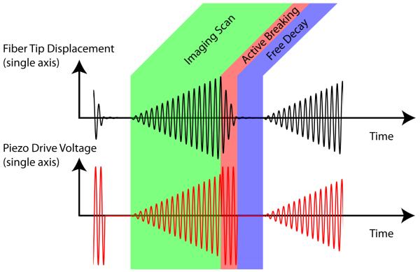
Most resonant mechanical devices are operated at a fixed frequency and amplitude. The SFE operation is unconventional, as the optical fiber cantilever is rapidly excited and actively damped. Each video frame consists of three distinct phases: imaging, active breaking, and free decay (Figure 2). Each frame is captured by scanning the image plane in an outwardly growing spiral pattern. This spiral pattern is generated by applying increasing sine and cosine drive functions in the x and y image plane axes. Modest amounts of phase and amplitude adjustment are applied to the drive signal to optimize scan circularity. Upon completion of the spiral scan, an active breaking sequence drives the fiber back to its rest position by applying a high amplitude drive signal that lags the fiber motion by 90°. This drive signal rapidly removes 95% of the scan motion in 5 to 30 cycles. Finally, actuation is halted, allowing the residual motion to decay naturally until the start of the next frame. Video imaging at 30 Hz and 500 lines per image is the standard scan setting. By changing these parameters, alternative frame sizes, shapes, and durations can be achieved. For example, the standard 500 line images at 30 Hz frame rate can be changed to 1000 line images at 15 Hz for increased spatial resolution and reduced temporal resolution in the form of frame rate.
Figure 2.
Electronic functional diagram of amplitude-modulated drive of the fiber scanner.
2.3. Calibrating the fiber scanner for high image quality
Closed-loop scanner feedback control is not required for maintaining high image quality for clinical applications. After the multi-lens assembly is aligned with the fiber scanner, the separation between fiber scanner tip and lens assembly determines the plane of sharpest focus. Typically, a low NA endoscope lens assembly is used (Pentax, HOYA Corp), resulting in a large depth of focus that is useful for resolving anatomical features over a large range of distances. The lenses can be adjusted during assembly to provide either 1-30 mm for small lumens or 2-60 mm for large lumens (Table 1). Other factors affect depth of focus, such as laser illumination power, number and size of collection fibers, sensitivity of light detection, and reflectivity of the object (tissue). The current SFE has laser powers of 1 mW blue (442 nm), 2 mW green (532 nm), and 2 mW red (635 nm) [18, 27]. Before initial use, the SFE probe is calibrated using a 2D position-sensing diode (UDT DLS-20) to maximize FOV, minimize scanner distortions, and provide white balance and chromatic compensation. A look-up table (LUT) can be used for each laser frequency to remap each point in the spiral scan pattern to a pixel position in rectilinear coordinates for electronic RGB digital display. In this way, sophisticated lateral chromatic aberration control is not necessary for the endoscope lens assembly. Each calibration setting is then stored as a file that can then be reloaded upon subsequent use, negating need for future recalibration under normal operating conditions. Closed-loop temperature stabilization is important for any resonant scanner, especially for in vivo environs, where temperature changes occur as a result of contact with tissue, biological fluids (blood, mucus, etc.), and flushing fluids (saline, anesthetics, etc.).
Table 1.
1.2 mm SFE standard components
| Part (quantity) | Dimensions | Description |
|---|---|---|
| Tube piezo (1) | 0.45 mm OD, 4 mm long | PZT5-A material |
| Drive electrodes (4) | 5 microns thickness | Nickel plate material |
| Scan fiber (1) | 0.080 mm OD, 2.27 mm long | Singlemode 0.13 NA 11 kHz res. freq |
| Lens assembly (1) | 0.80 mm apertures OD | 1-30 mm or 2-60 mm focal length, 100° FOV |
| Collection fibers (63) | 0.50 mm OD | 0.66 NA |
| Tip housing (1) | 1.2 mm OD, 9 mm long | Stainless steel material |
| Flexible shaft (1) | 1.2 mm OD, 1-4 m long | 6 mm minimum bend radius |
2.4. Imaging modalities
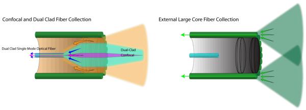
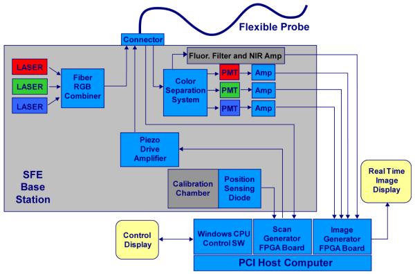
In the standard non-confocal SFE configuration, the RGB laser illumination is combined at the base station and coupled into the core of a singlemode optical fiber by a fiberoptic combiner or using free-space lenses and filters [18]. The resulting beam of RGB laser light is scanned and focused onto the image plane by a lens assembly that determines the maximum spatial resolution as defined by the point spread function (PSF). The standard (non-confocal) geometry collects backscattered light with a ring of high-NA multimode optical fibers that surround the fiber scanner and lens assembly (Figure 1 and Figure 3). The location, size, and number of these optical collection fibers determine the collection efficiency of the non-confocal SFE. This standard non-confocal geometry, which only uses the lens for illumination, is shown in Figure 3. Alternative SFE probe geometries are also shown, which include a dual illumination/collection lens configuration in a non-confocal geometry for two-photon fluorescence [23, 28-29] and confocal imaging for OCT [30]. Confocal geometries have the advantage of a smaller probe size, as a separate channel is not required for signal collection. However, the signal collection efficiency of non-confocal geometries is 40 times greater when collecting additional light from the inner cladding of a dual-clad optical fiber, especially at higher FOV [31-32]. Due to the back reflections in typical endoscope objective lenses, inner-cladding detection is ideally suited for fluorescence imaging. A block diagram of the non-confocal SFE system with concurrent fluorescence imaging in near-infrared (NIR) is shown in Figure 4. In the future, it should be possible to combine two or more of these different signal collection geometries to increase signal collection efficiency [33].
Figure 3.
Optical collection methods: confocal, dual-clad and external large core fiber
Figure 4.
Block diagram of the SFE color system with 4th channel for near infrared fluorescence.
2.5. SFE as platform technology
The SFE may be considered a platform technology for flexible endoscopy because many different imaging modalities can be achieved using the fiber scanner. This sub-millimeter optical scanner could replace the CCD imager and illumination fibers if sufficiently cost-effective for endoscope manufacturers. There is potential for high-volume mass production of the fiber scanner due to the simplicity of its design, which uses only a few low-cost components and may allow for disposable use (Table 1). The choice of the distal lens assembly determines the optical properties of the endoscope, such as spatial resolution, FOV and depth of focus. However, even with a fixed resonant frequency and lens assembly, imaging parameters can be modified for the application. This versatility of each SFE probe is apparent in the adjustable scan settings: changing the realized FOV by varying the scan amplitude, changing image resolution by varying the number of scan lines per image frame, and adjusting image contrast by varying the individual laser outputs and detector gains for fluorescence imaging and image processing for enhanced spectral imaging.
In addition to the large number of scan settings that can be adjusted during normal operation of the SFE, a number of alternative imaging modalities can be integrated with slight modifications to the system. Table 2 contains a list of SFE imaging modalities. Items 1-6 are achieved with the standard embodiment, while 7-12 list alternative imaging modalities and the required design modifications.
Table 2.
Listing of SFE features, 1-6 are standard and 7-12 require design modification
| # | Description of SFE feature |
|---|---|
| 1 | Full-color resolution (>500lines) with high FOV (75°) with adjustable zoom and frame rate |
| 2 | Enhanced spectral imaging for improved tissue contrast |
| 3 | Fluorescence imaging capabilities |
| 4 | 3D surface imaging |
| 5 | Spot optical spectroscopy at image center |
| 6 | Potential for disposable use of a sterile endoscope |
| 7 | Future laser therapies with dual-clad optical fiber |
| 8 | Additional illumination wavelengths (UV-NIR) using fused silica optical fiber |
| 9 | Confocal SFE achievable with spatial and chromatic filters and sensitive photodetector |
| 10 | OCT SFE achievable with low coherence source, reference arm and interference |
| 11 | Scanned two-photon fluorescence and second harmonic generation with fs-pulse laser output, special fiber, and high NA lens (see section 5.3) |
| 12 | Coherent AntiStokes Raman Scattering (CARS) SFE with ps-pulse laser outputs and moderate NA lens [122] |
3. Description of Standard SFE Features
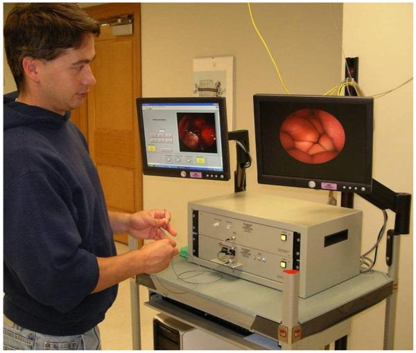
Many features of the SFE technology were proposed in 2002 by Seibel and Smithwick[16] and over the past eight years nearly all have been demonstrated in proof-of-concept SFE systems by our group and others (Figure 5).
Figure 5.
Photograph of SFE system being used to image within a closed fist of the operator.
3.1. High resolution within 1mm diameter
The SFE features that directly affect image resolution are the round co-axial geometry, high resolution spiral scanning method and RGB single mode laser illumination. Although coherent laser sources are often associated with interference effects such as speckle; consecutive pixels in the scanned field do not interfere with one another because of temporal separation. Furthermore the large area collectors in the non-confocal geometry of the SFE help to mitigate any coherence effects by integrating high spatial frequencies. Thus, adverse interference effects can reasonably be avoided in most applications, and to this date have not been a limiting factor in any SFE application. In 1 mm diameter packages, the current implementation of the SFE provides over 6 times the image resolution of flexible CFB technologies and over 2 times the projected resolution of custom full color silicon sensors. Additionally, the SFE has the ability to change FOV, resolution and frame rate during operation, allowing features such as electronic zoom and oversampling. A detailed discussion on resolutions, including basic assumptions and calculations is discussed in sections 4.2 – 4.5 and summarized in Table 3.
Table 3.
Technology Resolution Comparison
| System Performance (532 nm) | Diffraction Limited Performance (532 nm) | |||
|---|---|---|---|---|
| Device | Pixel Density pixels/mm2 |
Image Resolution pixels |
Pixel Density pixels/mm2 |
Image Resolution pixels in ∅0.85 mm |
| CFB | 113k | 30.0k/64.0k(1) | 1.92M | 1.08M |
| CCD/CMOS | 238k(2)/476k(3) | 95.0k(2)/190k(3) | 1.92M | 1.08M |
| SFE | 345k/496k(4,5) | 196k/282k(4) | 1.92M | 1.08M |
semi rigid
Bayer Filter
sequential color
26 Hz frame rate
virtual pixel density based on ∅0.85mm sample area
3.2. Flexibility of shaft
The minimum short-term bend radius of a single glass optical fiber of approximately 0.1 mm in diameter is typically 5 to 6 mm (www.stokeryale.com; www.nufern.com). In the case of CFB, thousands of smaller diameter optical fibers are rigidly combined to over 0.5 mm in diameter along the endoscope shaft so that the minimum bend radius escalates to centimeters with a concomitant high flexural rigidity. In comparison, the 1.2 mm SFE uses less than 70 loosely enclosed optical fibers within the shaft, thereby maintaining low flexural rigidity, and a minimum bend radius of roughly 6 mm. In both cases, flexural rigidity of the shaft must be increased to allow for pushability of the endoscope into the human body which can be achieved by adding wires, using thicker wall of sheathing, or using a more rigid insertion tube. In all SFE prototypes, length of the shaft is not a design limitation for deep explorations of the human body.
3.3. Scanner durability and safety
Any active device such as the electro-mechanical fiber scanner adds the theoretical risk that the moving part breaks and endoscope imaging ceases. A broken fiber does not affect patient safety as the fiber scanner is sealed within the endoscope tip with the lens assembly. During normal operation the laser power is less than 5 mW (equivalent to 3 laser pointers), which is less than standard endoscope illumination using arc lamp sources. The electrical voltages applied during operation of the SFE are quite low as the tube piezo is electrically equivalent to a small capacitor. Typical operating voltages are less than ±20 volts and electrical operating powers do not exceed 5.5 mW electrical power for video rate imaging at maximum FOV. In contrast, a CFB has no electrical requirement when the image capture device is at the proximal end outside the body. However, the CFB is considered mechanically fragile in a clinical setting. The shaft of the SFE is highly flexible and added stiffness can provide a high degree of mechanical durability and added electrical insulation. In theory, the fiber scanner can break, but upon normal operation the single illumination fiber does not fatigue or fail, even when driven beyond the maximum 100° FOV for over 250 billion cycles in one test [1] and over 275 billion driven scan cycles in a subsequent test that continually scanned for over a year. No fiber wear has been observed in these lifetime tests. During routine use, prototype fiber scanner systems have stopped working, typically due to cracking of the adhesive joint between the fiber scanner and tube piezo. In drop testing of fiber scanner at 2 m, the scanning illumination fiber never breaks, but sometimes the tube piezo cracks due to the high impact. Current SFE probes remain operational after repeated 1 m drop tests [1].
3.4. Depth imaging technologies
A minority of clinical practices rely on three dimensional (3D) surface imaging, although emerging endoscopic fields of neurosurgery and robotic surgery are demanding stereoscopic image acquisition. Due to the small size of the SFE, stereo systems can simply be realized with two separate endoscope systems running synchronously, with one channel (left eye) imaging while the other channel (right eye) is retracing and resting with no laser illumination. Alternatively, the two SFE systems can run asynchronously with different filtration channels to maintain separation of the two overlapping image fields. Depth to the tissue surface and topography can be calculated in a SFE endoscopic system using photometric stereo algorithms [34]. This application of 3D imaging requires at least two or three separate views from the same SFE probe. Multiple views of the same object can be generated by the same fiber scanner by collecting and detecting the backscattered light separately depending on the spatial location of the collection optical fibers located at the distal tip of the probe. For example, light collected from the left side of the probe will be shadowed more from a tissue protuberance on the left of the scanned illumination than the light collected from the right side of the probe. Depth can be determined by measuring the size of specular reflection pattern and using the lever arm analogy to estimate separation distance [35]. Subsurface tissue imaging is another form of 3D imaging but is limited to endomicroscopy techniques, such as confocal and optical coherence tomography (OCT), which is not covered in detail within this review.
3.5. Enhanced spectral imaging and multi-channel fluorescence imaging
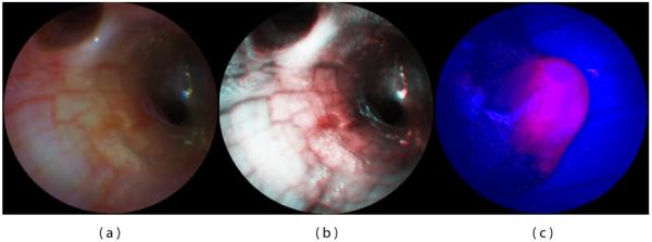
The SFE uses narrow bands of illumination light to produce full color images of tissue at high fidelity on flat surfaces. However, within a body lumen that is predominantly red in color (esophagus), the user typically reduces the gain on the red channel to produce more balanced color images. A recent innovation by Olympus has eliminated the red within the filtered white light imaging of conventional endoscopes for the purpose of enhancing blood vessel patterns within the subsurface tissue that are associated with cancer and other diseases [36]. For example, capillary networks in the surface mucosa can be imaged at higher contrast. Although tissue color is distorted, this form of enhanced spectral imaging (ESI) can be a standard feature of the SFE either during endoscopy or upon post-processing for computer-aided diagnosis [37]. Figure 6a depicts an endobronchial image within the airways of a live pig that is processed in Figure 6b to accentuate blood vessels and damaged tissue.
Figure 6.
SFE bronchoscopic image frames from standard RGB imaging at 500-line images at 30 Hz (a) and the corresponding ESI image (b) that increases contrast of blue laser light over the red laser light, helping to differentiate blood vessels and inflamed tissue. SFE fluorescence image acquired on the red channel showing hypericin localization within a tumor of renal cell carcinoma (c). Blue and green laser illumination was used while a small fraction of the blue backscattered light was collected to form the background structural image.
Wide field fluorescence imaging is also a standard feature of the SFE technology. For biomarkers used for Photodynamic Therapy (PDT) and Photodynamic Detection (PDD) that have wide excitation spectra, such as 5-ALA and hypericin [38], the RGB laser illumination can be used for both reflectance imaging and PDD/PDT applications. A proof-of-concept experiment was performed by perfusing hypericin into the vasculature of a rat kidney with renal cell carcinoma in situ and SFE fluorescence imaging on the red channel provided the cancer-specific image overlaid onto the structural image provided by the backscattered signal from the blue excitation light (Figure 6c) [39]. If a fourth detection channel is added for the deep red fluorescence imaging for such dyes as Cy5 (Figure 4), then fluorescence can be imaged concurrently with full-color (RGB) reflectance imaging. A fifth channel is often desired for subtracting the background signal from non-specific biomarker labeling for more clinical utility [40]. Again, the narrow laser bands for excitation lend itself to multi-channel fluorescence imaging either concurrently with RGB imaging or in a frame sequential manner.
3.6. Integrated spot diagnosis and therapy with imaging
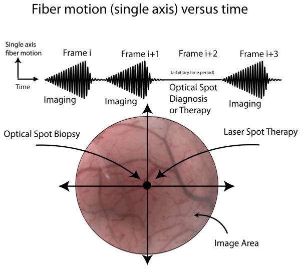
Between every imaging frame, the scanning fiber is brought to rest at the central pixel for microseconds to milliseconds for fluorescence spectral analysis of extrinsic biomarkers [41]. However, the duration of this rest phase can be lengthened to allow time for applications that require longer dwell times of laser illumination, such a laser-induced fluorescence spectroscopy of intrinsic biomarkers [19] (Figure 7). In cancer diagnosis, endoscopy is performed to locate suspicious tissue for biopsy (cell and tissue samples for cytology and pathology) [37]. Typically, the clinician steers the endoscope so the site location for biopsy is within the endoscope’s FOV for image-guided sampling. Performing a non-invasive optical biopsy at this location prior to real biopsy will give greater assurance that only the most suspicious tissues are being removed for further analysis. Optical spot biopsy has already been developed and tested for many different technologies in cancer detection, such as light scattering spectroscopy, laser-induced fluorescence spectroscopy, fluorescence lifetime analysis, and Raman spectroscopy [42-45]. Video imaging can be interrupted for the exact time needed to complete this optical diagnosis and resumed immediately after, thereby combining imaging and diagnosis in a frame sequential manner.
Figure 7.
Frame sequential imaging, diagnosis or therapy.
For highly efficient fluorescence microspheres, a spectrum of both laser excitation and fluorescence emission can be acquired within 3 ms using the standard SFE with tip bending (Figure 9) [41]. Thus, spectral analysis is possible during the fiber resting phase between SFE video image frames at 30 Hz. If these interruptions in SFE video imaging are brief, then frame sequential imaging, therapy, and monitoring are possible in the future. Laser spot destruction of tissue would be possible under near real-time monitoring in a frame-sequential imaging mode [46]. Alternatively, therapeutic drugs may be photo-actively released with a pulse of extended dwell time [47]. Since small, solid-core singlemode illumination fibers are restrictive in laser power delivery, a dual-clad optical fiber may be used for conveying higher laser power to the tissue. During the rest phase, the fiber delivers therapeutic laser power through the inner cladding, and during the scanning phase the fiber delivers imaging RGB illumination through the singlemode core. By hand scanning the endoscope tip, the pulsing high-power spot is slowly moved over the tissue while an image frame is generated by rapidly scanning low-power RGB light between therapeutic pulses. Thus, imaging and therapy are multiplexed in a frame-sequential time series allowing near real-time monitoring.
Figure 9.
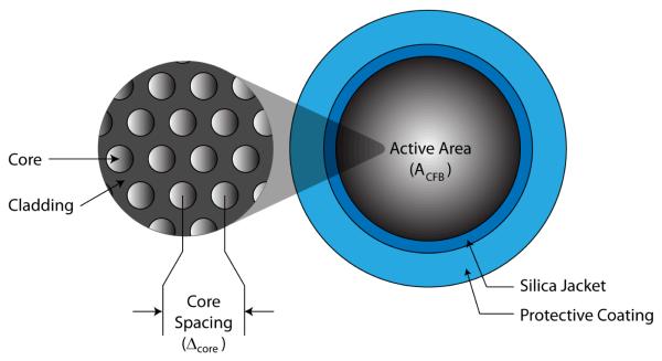
Fused coherent fiber bundle (CFB) cross sectional view
3.7. Summary of SFE features
The SFE technology allows a great variety of standard features to the clinician. Topics not discussed as part of the central design include active tip bending [37, 48] and in vivo tracking of the distal tip using electromagnetic sensors [49-50]. In the first half of Table 2, the basic features are listed for the standard (non-confocal) SFE imaging at video frame rates. With modifications to the standard SFE components and probe geometry, a wide range of non-standard features are possible, as listed in the second half of Table 2.
4. Ultrathin endoscopic technologies under development
The limitations of the CFB technology have been apparent to medical device engineers for the past twenty years, driving a number of alternative technologies that are surveyed in this section. The general clinical approaches have been improving upon the CFB, such as adding laser-scanning confocal imaging to improve spatial resolution and stitching multiple images into larger mosaics to overcome FOV limitations of confocal endomicroscopy (Mauna Kea Technologies, Paris, France) [51-52]. Although the CFBs have been used for imaging at high spatial resolutions via proximal-end laser scanning [9-10], the resulting in vivo confocal fluorescence microscopes provide only sub-millimeter FOV, thus restricting broad clinical utility. Consequently, the trend in clinical endoscopy has been to slowly replace fiberoptic systems with more expensive custom video chips at the endoscope tip [53-54]. The major flexible endoscope manufacturers (Olympus, Pentax, and Fujinon, all headquartered in Japan) have been placing a custom video chip camera at the endoscope distal end and expanding the image contrast by filtering the illumination light to include fluorescence and narrow band image processing. A wireless video chip camera with LED illumination is being used in the development of capsule endoscopes, such as Given Imaging, which uses a CMOS sensor [55] and Olympus, which uses a CCD [56].
4.1. Alternative scanning approaches to endoscopy
The newest technological approaches to high resolution imaging employ a micro-scanner placed at the distal tip of the endoscope. Most commonly, optical scanning is performed using a moving mirror in a confocaloptical geometry using microelectromechanical systems (MEMS) [57-62]. However, to achieve sub-cellular spatial resolutions, FOV must be sacrificed, hindering broad clinical utility. A wide-FOV MEMS endoscopic device has been designed using a 0.5 mm scan mirror, however, the packaging enlarges the device size to greater than 2 mm [63]. Unique circumferential line scanning has been demonstrated using a dual-reflectance large scan MEMS mirror, but again the device footprint is 2×2 mm2 [64]. Smaller device diameters are theoretically possible using the scanning of a MEMS cantilever originally proposed by Dickensheets & Kino [65] for a confocal geometry and by Wang et al. [66] in a non-confocal geometry. Ultimately, MEMS designs have not translated to the commercial market, possibly as a result of high fabrication set-up costs and limited application given the small FOV and relatively large diameters. A clinical solution, demonstrated by Kiesslich et al. [67], performed in vivo confocal imaging by scanning an optical fiber driven by an electromechanical motor. Though commercially available from Pentax, this 3D high-resolution imaging is housed within endoscope diameters greater than 10 mm which produces FOVs smaller than 1 mm.
Since MEMS optical scan systems tend to be much larger than 1 mm in diameter, alternative scanning strategies have been investigated with the goal of maintaining ultrathin device diameters. In a previous study, a 1 mm catheter has been rotated axially to scan a single beam in a 360° radial path [68]. The concept of rotational scanning was later extended to two dimensions using a line of near-infrared light generated from polychromatic illumination passing through a grating [69]. This spectrally encoded endoscopy technique has been shown to generate images beneath tissue surfaces using 860-880 nm light by increasing sensitivity [70]. Recently, a bench top version of this system has incorporated color imaging in the visible spectrum [71]. This same concept of using dispersion of broadband laser to spectrally encode and decode spatial information has been extended to 2D without need for any mechanical scan system [72]. Again this system has been proposed for endoscopy from a bench-top demonstration, but as a confocal system with limited FOV in the infrared spectrum [73]. These new technologies are very promising for miniaturization into ultrathin endoscopes. However, the requirement of polychromatic laser wavelengths interacting with dispersion elements in the visible spectrum in lieu of wide-field mechanical scanning may pose a significant technical challenge to translation into routine clinical use. Currently, the best clinical alternative to 2D scanning is rotation of a side-viewing endoscope while axially moving the scope within the lumen, albeit slowly, while generating 360° radial images [74].
4.2. Wide Field Endoscopic Imaging Limitations
The complication with producing high resolution in ultrathin flexible endoscopes is producing devices that are capable of effectively fitting and operating in the highly confined device. CFB and CCD technology used in modern endoscopes today, fail to take full advantage of the 1 mm area afforded inside the endoscope and as a result, produce less than optimal image quality. CFBs have remained the mainstay in small flexible scopes and provide sufficient sampling resolution in many applications. However, the low mechanical flexibility of the CFB deters the use of high core count bundles. For this reason, custom CCD and emerging Complementary Metal Oxide Semiconductor (CMOS) image sensors have strong potential to replace their glass counterpart, promising higher resolutions and better mechanical properties. However, expense and technical complication surrounding color, packaging and electronic characteristics, prevent their immediate adoption. Unlike traditional endoscope detectors, the flexible single mode fiber and coaxial scanning design of the SFE, take full advantage of the cylindrical space using spiral scan patterns that fill the entirety of the lens system.
The resolution considerations of CFB, CCD/CMOS, and SFE are described in more detail for the 1-mm size in the following sections (4.3 – 4.5). For comparative review, these results are tabulated in Table 3. In comparing imaging performance, other parameters are important for ultra-small imagers, such as dynamic range, signal-to-noise, and cross-talk, but will not be reviewed in order to retain some brevity. Before examining the details of current and future SFE technologies, a brief description of CFB, CCD and CMOS technologies is offered. CFB devices are used to transfer the image from the distal to proximal end of the endoscope by passively relaying light through a series of spatially aligned optical conduits. Either an eyepiece or video camera attachment captures images at the proximal end of the device. CCD and CMOS sensors are used to capture images at the distal end of the flexible endoscope and relay image electrical signals from the device. The basic photo conversion process of these two silicon devices is similar but their readout operations differ. Both CCD and CMOS technologies utilize an array of small photo diodes to capture spatial and intensity data. CCD pixels utilize a shifting mechanism that allows pixel charge to be transferred between adjacent pixels. In video full-frame transfer CCDs (FT-CCD) the pixel charge is first shifted off of the pixels to a buffer and then read out individually by a charge to voltage converter. CMOS sensors use a small transistor element for each pixel element, converting charge to voltage locally. A row and column addressing scheme is used to address and read from each pixel.
4.3. CFB Resolution Considerations
Today, most ultrathin endoscopes use small coherent fiber bundles that contain several thousand tightly packed optical cores (Figure 9). The spatial sampling period of these CFBs is determined by core size and spacing [75]; however, cross coupling effects between cores can reduce their effective sampling characteristics [76]. Cross coupling effects can be mitigated by providing adequate core separation, but this strategy can become counterproductive if applied too liberally. In small core systems, the core separation distance becomes a significant factor when determining the sampling characteristics of the device.
Commercial coherent fiber bundles are manufactured with cores diameters of 2 μm and core separation (Δcore) as small as 3.2 μm [4-5, 8]. Typical CFBs have a silica jacket and protective coating that combined take up a nominal 150 μm of the total diameter. Based on 60° alignment of cores, basic geometry can be applied to calculate a cross-sectional core density of 113k cores/mm2 in these CFBs (Equation 2).
By assuming the entire cross-sectional area in a ∅1 mm device could be fitted with the CFB, a prorated active area ACFB of 0.567 mm2 remains after accounting for space lost from the jacket and sheath. A display resolution of 64k pixels can be calculated from core density and active area (Equation 3). Unfortunately the implications of using such a thick CFB would cause the endoscope to have a cumbersome minimum bend radius of nearly 5 cm [4-5]. For this reason, small endoscope designs tend to use thinner CFBs yielding resolutions between 10k-30k pixels [6]. Alternatively, a bare 30k fiber bundle is used for combined illumination and imaging which results in reduced pixel numbers (<100 across FOV) and leads to fragility during clinical procedures [77-78].
| Equation 2 |
| Equation 3 |
For many years CFBs were used exclusively in flexible endoscopy, but their low durability and high rigidity were undesirable. The typical CFB endoscope suffers continual degradation of image quality over its lifetime, loosing pixels from core fractures within the bundle. Eventually the degradation becomes so severe the device is no longer suitable for use. Leached CFBs have solved some of the original durability issues, but with core spacing of 2.5 to 3 times of that in non-leached CFBs, their resolution is not yet competitive [14]. Since the inception of the CCD video scope, the CFB endoscope has slowly lost popularity. Small diameter endoscopes are one of the last applications where the CFB excels over the CCD. High pixel density, small form factor and low cost make the CFB sufficient for many ultrathin endoscope applications.
4.4 CCD/CMOS Resolution Considerations
Continuing improvement in CMOS and CCD sensor miniaturization, fueled by the commercial market for mobile phone and pc camera application, suggests the silicon sensor may soon overtake the CFB. State of the art research in silicon sensors has demonstrated 16×16 frame transfer CCD arrays with pixel element sizes as small as 0.5 μm × 0.5 μm [79]. More functional 3.0M pixel CMOS sensors with 1.45 μm pixel size [80] and 3.1M pixel FT-CCDs with 1.56 μm pixel size [81] have been successfully developed. This suggests that commercial silicon sensors may be capable of sampling beyond the diffraction limit of camera lens system.
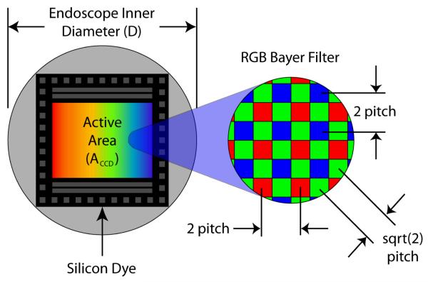
In practice several factors have prevented the silicon sensor from realizing the full potential of these small pixel sizes. The rectangular geometry associated with standard wafer cutting techniques limits the usable sensor area inside a cylindrical casing (Figure 10). Further loss is also experienced because the entire dye cannot be used for active sensing. Typically over 50% of the sensor dye space is used for wire bond points, keep-out area and supporting functionality such as frame buffers, pixel addressing and signal amplifiers. Additionally, complications including blooming, crosstalk, low dynamic range, and poor light collection surround further pixel size reduction [3] [82-83].
Figure 10.
CCD and CMOS Illustration
In addition to geometric limitations, color information comes at a cost. With the exception of the triple well active pixel sensor developed by Foveon [84] or frame sequential color [53], at least three different sensor elements are needed per color sample. A mosaic pattern of red, green and blue pixel sensors, referred to as the Bayer filter, is the most universal method for detecting color on a single chip [85]. This method reduces the fundamental linear sample frequency for red and blue to 50% and green to 70.7% of the pixel pitch. Because green is closely linked to our perception of luminance and spatial frequency, sampling effects of red and blue are less important. It has been suggested that resolution of a sensor using RGB sensing pixel element (Foveon) is as effective as a sensor twice to three times the area using a Bayer filter [86].
At this point there are no known commercial CCD or CMOS devices that are capable of fitting in a 1 mm diameter scope, but for comparison purposes we will consider highly specialized silicon sensor. Based on a 1.45 μm pixel pitch (Δ pixel) and 80% dye utilization DU such a sensor would capture 190K pixels images; however, after prorating the resolution affect associated with the Bayer filter only 63.4k-95.1k effective color pixels would be resolved.
| Equation 4 |
| Equation 5 |
From the resolution projections calculated from Equation 4 and Equation 5 it appears that silicon sensor resolution is superior to the CFB; however, these projected resolution numbers do not take into account higher order effects or manufacturing complications. It has been shown that decreasing pixel size can adversely affect resolution when there is low illumination and induced camera motion, suggesting that slightly larger pixel elements more practical [82].
4.5 SFE Resolution Considerations
The SFE sample resolution, unlike CCD, CMOS or CFB technology, is not fixed by the physical size and spacing of pixel elements. Instead the scanning motion and sampling rate determine the sample spacing. Because neither of these parameters is fixed during fabrication, the device resolution, scan angle and frame rate are readily adjustable. In practice, mechanical properties limit the number of reasonable scan patterns that can be produced. These producible scan patterns generally exhibit non-uniform sampling and retrace that reduce their effective pixel count and frame rate. In addition, scan behavior is also subject to distortion caused by non ideal dynamic system behavior and actuator limitations. Although real-time closed loop control methods have been used to reduce scan error, the space limitations of clinical devices preclude the use of bulky position sensing diode sensors [87]. With improved construction techniques, scanning systems today exhibit highly repeatable scan patterns, making open loop methods a viable solution [18, 88].
The 11 KHz micro scanner in the SFE produces 250 radially increasing spirals followed by a nominal 20-30 active breaking cycles and 50-60 free decay cycles. The entire scan process has a period of 1/30th of a second. At the sample rate is 25 MSps a total of 625,000 samples are captured and mapped to circular image with effective display resolution to 196k pixels [1]. Similarly the scan pattern has been run at slightly reduced frame rates of 26 Hz allowing for an additional 50 image spirals. This modified scan captures a total of 750,000 samples that map to an effective display resolution of 282k pixels. In summary the SFE in its current incarnation is capable of significantly higher sampling then CFB, CCD and CMOS in 1 mm devices and it is capable of adjusting frame rate and resolution (Table 3).
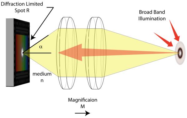
Although sensor limitation can be used to differentiate the SFE from CFB, CCD and CMOS technologies, all flexible endoscope designs are limited by the diffraction of light (Figure 11). The spatial point spread function (PSF) imparted on the image is determined by both the objective lens and the illumination properties. In endoscopes, this PSF has the largest effect at the real focal plane inside the device. The limited area within the device and the resolvable separation between points can be used to calculate the image resolution in this wide FOV application. Rayleigh (Equation 7) and Sparrow (Equation 8) resolution criteria can be used to quantify the minimum resolvable separation between points, where NA indicated the numerical aperture lens and λ the illumination wavelength. The NA of the objective can be quantified using Equation 6 relating the convergence angle α and the index of refraction n, of the medium inside the scope. For calculation purposes, we will use the Sparrow criterion, because it is based on human perceptual factors and can be applied to a variety of PSFs including Airy Disk and Gaussian Beam [89].
| Equation 6 |
| Equation 7 |
| Equation 8 |
Figure 11.
Traditional Endoscope Optics
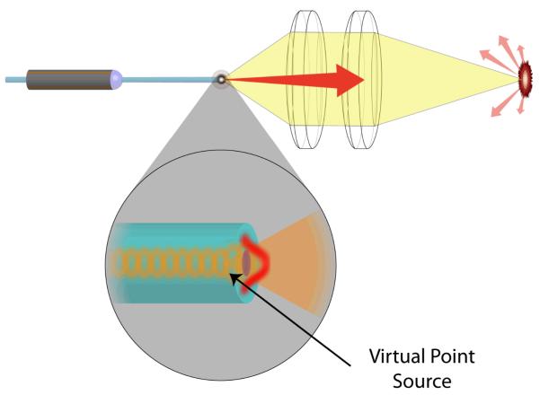
For a fully illuminated objective, with NA of 0.35 and central wavelength of 53 nm, 479k points can be resolved per square mm using Sparrow criteria. At minimum Nyquist sampling, this equates to approximately, 1.92M pixels mm2, or 1.08M pixels on a ∅0.85 mm diameter area behind the lens. The SFE has the unique capability of sampling at the lens limitations because a virtual point source is formed at the tip of the fiber when the coherent light exits the single mode core (Figure 12) [90]. Assuming there are negligible aberration effects, this point source is capable of realizing the diffraction limited PSF.
Figure 12.
SFE Optics
In previous studies, this sampling characteristic of the SFE has been used to perform electronic zooming by reducing fiber deflection to narrow the FOV (Figure 13). This equates to higher angular resolution up to the optical limitations of the lens. Although, in this particular case, over sampling was used to achieve a zoom effect, in conjunction with de-convolution algorithms, enhanced frequency contrast and phase accuracy are possible.
Figure 13.
Scan adaption for electronic zoom
5. SFE Applications
The SFE technology has been tested in vivo in large lumens organs of the human upper digestive tract (esophagus and stomach) down to small lumens within the pig airways and bile duct. With an optical window at the lens distal end, the SFE images equally well in air or liquid.
5.1. Tethered capsule endoscope (TCE) in esophagus
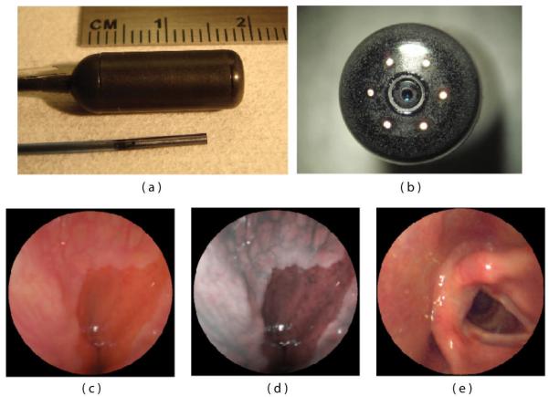
The first clinical application of the SFE was in the form of self-experimentation of the principle investigator using a swallowable version, called the tethered capsule endoscope (TCE) (Figure 14)[27]. The larger TCE probe is shown in relation to the 1.2-mm diameter SFE in Figure 14 a,b. Parallel to the 1.4 mm tether of the TCE is an air channel to allow for insufflations of the esophagus to facilitate imaging of the first healthy subjects without any adverse effects [91]. The ability to insufflate allows for rapid imaging of the gastroesophageal junction in unsedated patients because bubbles can be quickly removed from the FOV and the pressure can trigger the opening of this junction in order to detect inflammation and Barrett’s esophagus, a pre-cancerous condition. While standard TCE imaging is similar to white-light imaging, the RGB laser sources allows for post-imaging processing akin to commercially available narrow band imaging [92] in order to improve visualization of mucosal detail [37, 91] (Figure 14c,d). While wireless capsule endoscopy is currently available to image the esophagus, this technique does not allow for insufflations of the esophageal lumen, nor is control of the imaging field by the endoscopist possible as illustrated in the vocal chord image (Figure 14e). Untethered capsule endoscopy has shown no clear advantage over conventional endoscopy [93]. However, tying a string on the wireless capsule endoscope to allow for reusability and physician control like the TCE has shown higher performance and lower cost than conventional endoscopy [94]. Laser-based imaging in combination with image processing for comprehensive surveillance of the esophagus has been demonstrated for 3D-OCT monochrome analysis [95] and for 2D-TCE color analysis [27]. A future goal is to reliably detect high-grade dysplasia in Barrett’s esophagus [96] with a combination of SFE technologies, such as wide-field fluorescence imaging and mosaicing [97].
Figure 14.
SFE endoscope probes showing 9 mm rigid tip length of 1.2 mm diameter prototype and 18 mm capsule length of ∅6.4 mm diameter TCE. A front view of the distal end of the TCE is shown in (b) illustrating that the TCE is a standard SFE probe with collection fibers modified for capsule use. The gastroesophageal junction of a human subject is shown in single 500-line RGB image contrast (c) compared to post-processed ESI contrast of the same SFE image frame (d). The lighter esophageal tissue is more clearly differentiated from the red colored gastric mucosa in the ESI image. An image of the human vocal chords is shown in (e).
5.2. SFE in airways
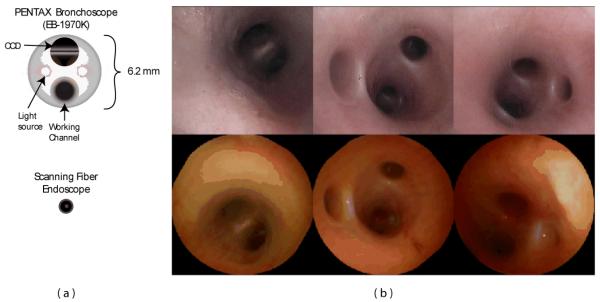
The first in vivo experiment using the SFE was performed to examine of the airways of a live pig. The SFE is particularly relevant to bronchoscopy given the incidence of lung cancer, need for improved diagnostic instruments, and small lumen sizes being accessed. At present, computed tomography (CT) scans indicate the presence of numerous pulmonary nodules within patients suspected of having lung cancer. However, due the invasive nature of surgically resecting such nodules and the potential loss of lung function, intervention is reserved for patients in whom a malignant diagnosis is highly suspect. Biopsy of a nodule provides the best chance at accurate diagnosis. Bronchoscopy is considered to be the most minimally invasive of biopsy procedures, but the accuracy of the procedure is inhibited by inability to extend conventional bronchoscopes into small airways where these nodules occur. However, the accessible lung volume afforded by the small SFE is significanty greater. Whereas conventional bronchoscopes, with an outer diameter of approximately 6 mm (Figure 15a), are limited to the first four airway generations (24 or 16 airways), the SFE is capable of insertion through 8 to 10 branching generations, amounting to several hundred or thousand airways.
Figure 15.
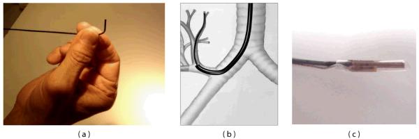
Diagrams of a conventional Pentax bronchoscope (EB-1970K) and SFE (a) and corresponding bronchoscopic images within the airways of a pig.
SFE-based examination of these peripheral nodules is highly practical. First, patients identified with lesions would be able to undergo bronchoscopy for a more definitive diagnosis. This would obviate more invasive transthoracic biopsy procedures as well as the repeated CT scanning performed as part of ongoing surveillance of nodules not deemed large enough to merit initial intervention. Using the SFE, bronchoscopy can be performed without need of expensive imaging systems and surgical suites, and can be used in conjunction with conventional bronchoscopes through the 2.4 mm working channel.
Figure 15b compares bronchoscopic images of the airways in a live pig acquired from both a conventional Pentax bronchoscope and the SFE. The resolution and field of view of the two devices are comparable despite a four-fold reduction in size of the SFE. The color discrepancy is due to the illumination sources; conventional bronchoscopes use an arc-lamp while the SFE uses red, green, and blue laser diodes. The conventional bronchoscope is not capable of extending much further than third or fourth generation airways. However, the SFE could be extended a number of generations further into peripheral airways.
In practical consideration of implementing the SFE as part of a complete bronchoscopic system, a number of additional features are being incorporated into a system for image-guided bronchoscopy. First, a steering mechanism is being constructed to permit articulation of the SFE (Figure 16a). A large bend angle of 90° and small bend radius (6 mm) will allow the SFE to negotiate sharp bend angles to access upper airway regions (Figure 16b). To assist the bronchoscopist in navigating multiple airway generations, a virtual guidance system has been developed to track the position of the SFE [49-50]. Intraoperative localization is achieved through integration of a miniature (0.30 mm) electromagnetic position sensor (Ascension Technology Corporation, Burlington, VT) that can be used to locate the SFE in 3D space (Figure 16c). Custom biopsy tools have been proposed that are introduced over the SFE that is a steered and tracked catheterscope, such as a cannula-style tube for lavage, brush for cytological sampling and cutting needle for tissue biopsy [98].
Figure 16.
Additional features are incorporated into the SFE design to permit bronchoscopic examination of small peripheral airways include: a steering mechanism (a) and guidance system that is used to locate SFE by means of a miniature (0.30 mm) sensor.
5.3. SFE in biomedical research
In addition to endoscopic imaging for clinical diagnosis and treatment, miniaturized fiber-optic imaging devices such as the SFE also open up new ways for microscopy studies in biomedical research fields like neuroscience. Overviews of different ongoing technological developments in this area can be found in [99-102]. In neuroscience the development of miniature, lightweight fiber-optic microscopes [23, 60, 75, 103-106] is leading towards two longstanding goals of cellular-resolution brain imaging: First, endoscopic approaches promise to enable high-resolution imaging from deep brain areas, which are otherwise inaccessible for optical analysis. Second, small portable microscopes will permit measurements of the neural dynamics underlying specific behaviors in awake, freely moving animals, thus overcoming the limitations of current in vivo experiments under anesthesia which suffer from alterations in neuronal and astrocytic activities.
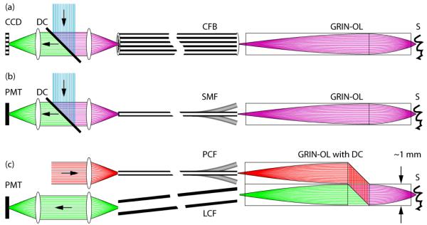
Unlike the catheterscopes described above that allow imaging with large FOVs, neuroscientific applications aim at micrometer-resolution imaging of individual cells. As a consequence, different front lens systems with high NAs are required, which however limit the FOV to a few hundred micrometers. In principle, single-photon or two-photon fluorescence excitation modes can be used, both featuring certain advantages and disadvantages (Error! Reference source not found.Error! Reference source not found.Figure 17). Miniature microscopes have been realized as either wide-field CFB-type or scanning-type fiberscopes. In the latter case scanning is performed either at the proximal end of a CFB [75] or at the distal end with a single-mode fiber scanner [18, 23, 103-104]. Recently, the construction of a portable CFB-type fiberscope has enabled investigators to visualize blood flow in hippocampus and to measure neuronal calcium dynamics in cerebellar Purkinje cell dendrites in freely moving mice [105]. Advantages of the single-photon CFB approach are fast acquisition rates (usually only limited by the camera speed), relatively large FOVs, and mechanical simplicity and rigidity. Disadvantages include limited optical penetration depths due to strong light scattering in neural tissue, increased background fluorescence levels, decreased contrast levels, and potentially high photobleaching rates due to out-of-focus excitation.
Figure 17.
Fundamental overview of different fiberscope types used in biomedical research. (a) CFB-based fiberscope, usually implemented as single-photon excitation wide-field type. An image of the sample S is propagated through the gradient-index objective lens GRIN-OL and the coherent fiber-bundle CFB and remotely detected using a CCD-chip behind a dichroic beam-splitter DC (green rays). Fluorescence excitation light travels to the sample in the reverse direction (blue rays). In principle, this type can also be used in combination with proximal (on the optical table) beam scanning for single- and two-photon excitation microscopy. (b) Scanning type fiberscope, usually implemented as single-photon or two-photon excitation microscope. Fluorescence excitation light (blue rays) is guided to the distal fiberscope head-piece via DC and through a single-mode fiber SMF and is focused onto S via GRIN-OL. Fluorescence emission light (green rays) is usually proximally detected by a photomultiplier tube PMT after traveling the reverse direction. Distal beam scanning is usually achieved by either resonant fiber scanners, or MEMS scanners. Fluorescence detection efficiencies can be improved with dual-clad fibers. (c) Scanning type fiberscope, usually implemented as two-photon excitation fiberscope. Dichroic beam-splitting occurs distally in a custom microprism arrangement that is part of GRIN-OL. Near-infrared fluorescence excitation photons (red rays) are guided through a photonic crystal fiber PCF that permits distorsion-free delivery of femtosecond pulses. Fluorescence emission photons from S are remotely detected by a PMT after traveling through a large-core fiber LCF for improved efficiencies.
In two-photon microscopy [107] reduced scattering at longer wavelengths, spatial localization of fluorescence excitation, and low phototoxicity lead to distinct advantages for deep-tissue imaging [108-109]. The development of miniaturized two-photon fiberscopes has therefore gained particular interest in brain research. Two-photon fiberscopes typically utilize 100 fs pulses of near-infrared light for fluorescence excitation. Because of the group delay dispersion introduced by the fiber material as well as nonlinear effects at high intensities these pulses are broadened several-fold in standard single-mode fibers, reducing the efficiency of two-photon excitation. This problem can be alleviated or circumvented, however, by using special photonic crystal fibers (PCFs) for efficient pulse delivery [22-23, 104, 110-111]. Moreover, various fiber scanning approaches have been implemented including resonant fiber vibrations [23, 103-104], fiber tip deflection [112], and microelectromechanical systems with small mirrors [60, 106, 113-114]. The laser output from the scanning fiber tip typically is imaged through a gradient-index (GRIN) lens objective [9, 23, 75, 104, 115], while fluorescence emission is collected through a second large-core optical fiber [23] or a dual-clad fiber [29, 116-117], or is detected with a small photodetector integrated in the fiberscope front piece [103, 118]. Most technological approaches so far have used GRIN lenses with moderate NAs in the range of 0.5. Therefore, theses systems were able to resolve fluorescent structures in the micrometer regime but were outperformed by standard, higher-NA two-photon microscopes. Newly developed GRIN-assemblies can have NAs of up to 0.85 and therefore exhibit even higher optical resolution and better light collection efficiencies [106, 119]. However, application of these high-NA systems in miniaturized microscopes is still pending. The formation of lenses on the fiber tip itself [120] might be an interesting alternative for further miniaturization attempts, albeit at the cost of decreased NAs.
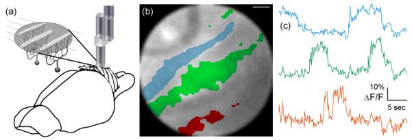
Using the SFE technology in combination with a specialized hollow-core PCF [22] we constructed an ultra-compact (0.6 grams) fiber-optic two-photon microscope [23]. Laser pulses from a Ti:Sapphire laser system were coupled into the hollow-core PCF and guided to the microscope headpiece with minimal group velocity dispersion (GVD). The tip of the illumination fiber was resonantly vibrating in a spiral trajectory, which was then imaged onto the sample by a 1 mm-diameter GRIN-lens assembly consisting of collimator, beam splitter, objective lens, and detection fiber coupler as described in Figure 17. Fluorescence emission was guided through the objective lens, beam splitter, fiber coupler, detection fiber, and remotely detected by a photomultiplier tube (PMT). The PMT-current signal was amplified and digitized by a multifunction data acquisition (DAQ) board and fluorescence intensity values were assigned to their corresponding pixels based on a static lookup-table (LUT). Optionally, image distortions can be corrected for by remapping pixels, applying a previously measured LUT using the same procedures as described above. Achievable FOVs were 200 μm in diameter. Frame rates critically depended on the spiral parameters used for imaging with typical values being video-rate (25 Hz) before averaging. Lateral and axial spatial resolutions (full widths at half maximum, FWHM) were measured to be 0.98±0.09 μm and 7.68±1.30 μm, respectively with subresolution fluorescent microspheres. Using this device we could demonstrate the instrument’s suitability for functional calcium imaging of neuronal activity in the intact brain of an anesthetized rat (Figure 18). With a slightly larger two-photon fiberscope another group recently succeeded in imaging single-cell activity in the visual cortex of freely moving rats [121] indicating that high-resolution calcium imaging studies in freely behaving animals with miniaturized two-photon microscopes are imminent.
Figure 18.
Fiberscope data acquired from rat cerebellum. (a) Anatomical organization of the rat cerebellar cortex. Flat dendritic trees of Purkinje cells form parasagittal planes that appear as band-like structures when observed from above. (b) Region-of-interest (ROI) selection (colored areas) can be a semi-automated process based on independent component analysis (ICA). (c) Spontaneous ΔF/F traces that are color coded to match the ROI selections in (b). Scale bar is 15 μm. Reproduced with permission from [23].
Future versions of SFE-based miniature fluorescence microscopes could benefit from high-NA GRIN lens assemblies leading to higher resolutions and better light collection efficiencies. Furthermore, elongated thin front lens systems may allow imaging of deeper brain structures and readout of neuronal activity patterns. Finally, optimized driving and fiber braking schemes could improve frame rates as well as spiral stability. Overall, the combination of novel fluorescent probes (e.g. fluorescent protein expression in transgenic animals) with the highly flexible SFE technology promises to reveal detailed information about fundamental physiological processes as they occur in the living animal.
6. Conclusions and future directions
High performance ultrathin endoscopes and catheterscopes are the technological basis for image-guided medical procedures deep within the body, often with unsedated patients, which lowers risk and cost. In the future, soft and flexible endoscopes may be quasi-implantable so that more chronic conditions can be monitored through longer-term dynamic monitoring. Furthermore, the ultrathin size of the SFE allows insertion into the body through a 16-gauge needle, which is no longer considered surgery as anesthesia and suturing is no longer required. The catheterscope is essentially a guidewire with eyes, over which cannula-style tools can be introduced for cell sampling and biopsy. Similar to interventional cardiology, the SFE catheter and associated tools may be sufficiently low in cost to be disposable and device sterility can be assured.
The micro-laser scanning of the SFE technology allows many of the most advanced microscopic techniques developed for in vitro analysis to now be conducted in vivo. An analogous transition has already occurred in many research laboratories, switching from wide-field optical microscopy to laser scanning microscopy for diagnostic imaging and laser dissection. By using active laser scanning, the catheterscope can be used for integrated imaging, diagnosis, therapy, and monitoring in a frame-sequential basis. Since a vast majority of cancers originate in the epithelium layer, laser biomarker diagnostics may be the preferred approach to identify and diagnose the earliest cancers. Using pixel-level control of the laser sources, the SFE technology can then be used to destroy these early cancers in situ with minimal healthy tissue damage. In vivo use the laser-based catheterscope is assisted by the growing use of fluorescence biomarkers and gold nanoparticles with molecular-specific binding to disease for integrated diagnosis and treatment. As reviewed here, the SFE technology provides the affordance of new directions and concepts in clinical medicine and basic medical research.
Figure 8.
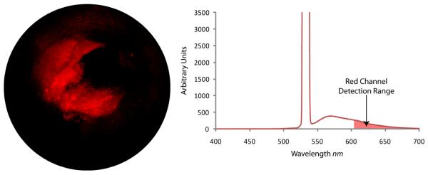
SFE video frame (left) of fluorescence microspheres (Nile-red FluoSphere, F-8819, Molecular Probes) embedded within a synthetic phantom of a bile duct. Optical spectral analysis (right) that shows the high laser illumination at 532 nm and fluorescence emission when collection optical fibers are connected to a spectrometer (USB2000-FL, Ocean Optics). SFE red channel detection range is illustrated on the spectral plot.
Acknowledgement
Current and past clinical collaborators with Dr. Seibel, especially: Drs. J. Dominitz, R. Yeung, M. Saunders, R. Glenny, D. Haynor, J. Chien, T. Brentnall, M. Kimmey, and M. Sinanan.
All members of the Human Photonics Lab and past members of the Human Interface Technology Lab who have contributed in great and small to this project: R. Johnston, C. Melville, M. Kundrat, D. Gertler, W. Yoon, C. Brown, Q. Smithwick, E. Barhoum, M. Fauver, J. Myers, J. Crossman-Bosworth, B. Murray and T. Furness. However, this research would not have been possible without the expertise in design, development and testing from Mr. C. D. Melville and Mr. R. S. Johnston.
Current funding is from NIBIB (R01008119 and RC1EB010900), NCI (U54 CA136429 (Wang), and CA 128231 (Dominitz)), and the W. H. Coulter Foundation. Past support which developed this technology came from The Whitaker Foundation, Washington Technology Center, NSF CBET 0809070, NIH/NCI (R21 CA110184, R21/R33 CA094303) and PENTAX (HOYA Corporation) with special appreciation to Dr. H. Baker, Mr. T. Hidaka, and Mr. T. Shimada. Research support in the Helmchen lab was from the Human Frontier Science Program, the Swiss National Center for Competence in Research “Neural Plasticity and Repair”, and the EU-FP7 program (project 200873).
References
- [1].Seibel EJ. 1-mm catheterscope. Optical Fibers and Sensors for Medical Diagnostics and Treatment Applications VIII, Proc. SPIE. 2008;6852:685207–8. [Google Scholar]
- [2].Hirschowitz BI, Curtiss LE, Peters CW, Pollard HM. Demonstration of a new gastroscope, the fiberscope. Gastroenterology. 1958;35(1):50. discussion 51-3. [PubMed] [Google Scholar]
- [3].Baillie J. The endoscope. Gastrointest Endosc. 2007;65(6):886–93. doi: 10.1016/j.gie.2007.01.032. [DOI] [PubMed] [Google Scholar]
- [4].Fujikura . FIA:Image Fiber. Fujikura; 2009. [Google Scholar]
- [5].Sumitomo 2009 http://www.sumitomoelectricusa.com.
- [6].Funovics MA, Weissleder R, Mahmood U. Catheter-based in vivo imaging of enzyme activity and gene expression: feasibility study in mice. Radiology. 2004;231(3):659–66. doi: 10.1148/radiol.2313030831. [DOI] [PubMed] [Google Scholar]
- [7].Muldoon TJ, Pierce MC, Nida DL, Williams MD, Gillenwater A, Richards-Kortum R. Subcellular-resolution molecular imaging within living tissue by fiber microendoscopy. Opt Express. 2007;15(25):16413–23. doi: 10.1364/oe.15.016413. [DOI] [PMC free article] [PubMed] [Google Scholar]
- [8].Udovich JA, Kirkpatrick ND, Kano A, Tanbakuchi A, Utzinger U, Gmitro AF. Spectral background and transmission characteristics of fiber optic imaging bundles. Appl. Opt. 2008;47(25):4560–4568. doi: 10.1364/ao.47.004560. [DOI] [PubMed] [Google Scholar]
- [9].Knittel J, Schnieder L, Buess G, Messerschmidt B, Possner T. Endoscope-compatible confocal microscope using a gradient index-lens system. Optics Communications. 2001;188(5-6):267–273. [Google Scholar]
- [10].Sung KB, Liang C, Descour M, Collier T, Follen M, Richards-Kortum R. Fiber-optic confocal reflectance microscope with miniature objective for in vivo imaging of human tissues. IEEE Trans Biomed Eng. 2002;49(10):1168–72. doi: 10.1109/TBME.2002.803524. [DOI] [PubMed] [Google Scholar]
- [11].Rouse AR, Kano A, Udovich JA, Kroto SM, Gmitro AF. Design and demonstration of a miniature catheter for a confocal microendoscope. Applied Optics. 2004;43(31):5763–5771. doi: 10.1364/ao.43.005763. [DOI] [PubMed] [Google Scholar]
- [12].Oki M, Saka H, Kitagawa C, Sako C, Tanaka S, Kawada Y, Mori K. Visceral Pleural Perforation in Two Cases of Ultrathin Bronchoscopy*. Chest. 2005;127(6):2271–2273. doi: 10.1378/chest.127.6.2271. [DOI] [PubMed] [Google Scholar]
- [13].Suter MJ, Riker DR, Mino-Kenudson M, Thiesse J, Rosenberg M, Gallagher KA, Shishkov M, Bouma BE, Beamis JF, Tearney GJ. Volumetric microscopy of the bronchial mucosa with high resolution optical frequency domain imaging: a preclinical safety and pilot clinical study. Am J Resp Crit Care. (submitted) [Google Scholar]
- [14].Schott . SCHOTT North America - Image Bundle. 2009. [Google Scholar]
- [15].Oyster CW. The human eye structure and function. Sinauer Associates, Inc.; Sunderland, MA: 1999. [Google Scholar]
- [16].Seibel EJ, Smithwick QYJ. Unique features of optical scanning, single fiber endoscopy. Lasers in Surgery and Medicine. 2002;30(3):177–183. doi: 10.1002/lsm.10029. [DOI] [PubMed] [Google Scholar]
- [17].Seibel EJ, Smithwick QYJ, Brown CM, Reinhall PG. Single-fiber flexible endoscope: general design for small size, high resolution, and wide field of view. Biomonitoring and Endoscopy Technologies, Proc. SPIE. 2001;4158:29–39. [Google Scholar]
- [18].Seibel EJ, Johnston RS, Melville CD. A full-color scanning fiber endoscope. Optical Fibers and Sensors for Medical Diagnostics and Treatment Applications VI, Proc. SPIE. 2006;6083:608303–8. [Google Scholar]
- [19].Seibel EJ, Brown CM, Dominitz JA, Kimmey MB. Scanning single fiber endoscopy: a new platform technology for integrated laser imaging, diagnosis, and future therapies. Gastrointest Endosc Clin N Am. 2008;18(3):467–78. viii. doi: 10.1016/j.giec.2008.05.001. [DOI] [PMC free article] [PubMed] [Google Scholar]
- [20].Giniunas L, Juskaitis R, Shatalin SV. Endoscope with optical sectioning capability. Applied Optics. 1993;32(16):2888–2890. doi: 10.1364/AO.32.002888. [DOI] [PubMed] [Google Scholar]
- [21].Kinsler LE, Frey AR, Coppens AB, Sanders JW. Fundamental of Acoustics. John Wiley & Sons; New York: 1982. [Google Scholar]
- [22].Göbel W, Nimmerjahn A, Helmchen F. Distortion-free delivery of nanojoule femtosecond pulses from a Ti : sapphire laser through a hollow-core photonic crystal fiber. Opt Lett. 2004;29(11):1285–1287. doi: 10.1364/ol.29.001285. [DOI] [PubMed] [Google Scholar]
- [23].Engelbrecht CJ, Johnston RS, Seibel EJ, Helmchen F. Ultra-compact fiber-optic two-photon microscope for functional fluorescence imaging in vivo. Opt Express. 2008;16(8):5556–64. doi: 10.1364/oe.16.005556. [DOI] [PubMed] [Google Scholar]
- [24].Smithwick QYJ, Reinhall PG, Vagners J, Seibel EJ. A Nonlinear State-Space Model of a Resonating Single Fiber Scanner for Tracking Control: Theory and Experiment. Journal of Dynamic Systems, Measurement, and Control. 2004;126(1):88–101. [Google Scholar]
- [25].Brown CM, Reinhall PG, Karasawa S, Seibel EJ. Optomechanical design and fabrication of resonant microscanners for a scanning fiber endoscope. Optical Engineering. 2006;45(4) [Google Scholar]
- [26].Seibel EJ, Brown CM, Kundrat MJ, Reinhall PG. Modeling optical fiber dynamics for increased efficiencies in scanning fiber applications. Proc. SPIE. 2005;5691:42–53. [Google Scholar]
- [27].Seibel EJ, Carroll RE, Dominitz JA, Johnston RS, Melville CD, Lee CM, Seitz SM, Kimmey MB. Tethered capsule endoscopy, a low-cost and high-performance alternative technology for the screening of esophageal cancer and Barrett’s esophagus. IEEE Trans Biomed Eng. 2008;55(3):1032–42. doi: 10.1109/TBME.2008.915680. [DOI] [PubMed] [Google Scholar]
- [28].Wu YC, Xi JF, Cobb MJ, Li XD. Scanning fiber-optic nonlinear endomicroscopy with miniature aspherical compound lens and multimode fiber collector. Optics Letters. 2009;34(7):953–955. doi: 10.1364/ol.34.000953. [DOI] [PMC free article] [PubMed] [Google Scholar]
- [29].Myaing MT, MacDonald DJ, Li X. Fiber-optic scanning two-photon fluorescence endoscope. Opt Lett. 2006;31(8):1076–8. doi: 10.1364/ol.31.001076. [DOI] [PubMed] [Google Scholar]
- [30].Liu XM, Cobb MJ, Chen YC, Kimmey MB, Li XD. Rapid-scanning forward-imaging miniature endoscope for real-time optical coherence tomography. Optics Letters. 2004;29(15):1763–1765. doi: 10.1364/ol.29.001763. [DOI] [PubMed] [Google Scholar]
- [31].Barhoum E, Johnston R, Seibel E. Optical modeling of an ultrathin scanning fiber endoscope, a preliminary study of confocal versus non-confocal detection. Opt. Express. 2005;13(19):7548–7562. doi: 10.1364/opex.13.007548. [DOI] [PubMed] [Google Scholar]
- [32].Fu L, Gan XS, Gu M. Nonlinear optical microscopy based on double-clad photonic crystal fibers. Optics Express. 2005;13(14):5528–5534. doi: 10.1364/opex.13.005528. [DOI] [PubMed] [Google Scholar]
- [33].Engelbrecht CJ, Göbel W, Helmchen F. Enhanced fluorescence signal in nonlinear microscopy through supplementary fiber-optic light collection. Opt Express. 2009;17(8):6421–35. doi: 10.1364/oe.17.006421. [DOI] [PubMed] [Google Scholar]
- [34].Smithwick QYJ, Seibel EJ. Depth enhancement using a scanning fiber optical endoscope. Proc. SPIE. 2002;4613:222–233. [Google Scholar]
- [35].Haneishi H, Ogura T, Miyake Y. Profilometry of a gastrointestinal surface by an endoscope with laser beam projection. Opt. Lett. 1994;19(9):601–603. doi: 10.1364/ol.19.000601. [DOI] [PubMed] [Google Scholar]
- [36].Yao K, Takaki Y, Matsui T, Iwashita A, Anagnostopoulos GK, Kaye P, Ragunath K. Clinical application of magnification endoscopy and narrow-band imaging in the upper gastrointestinal tract: new imaging techniques for detecting and characterizing gastrointestinal neoplasia. Gastrointest Endosc Clin N Am. 2008;18(3):415–33. vii–viii. doi: 10.1016/j.giec.2008.05.011. [DOI] [PubMed] [Google Scholar]
- [37].Seibel EJ, Brentnall TA, Dominitz JA. New endoscopic and cytologic tools for cancer surveillance in the digestive tract. Gastrointest Endosc Clin N Am. 2009;19(2):299–307. doi: 10.1016/j.giec.2009.02.002. [DOI] [PMC free article] [PubMed] [Google Scholar]
- [38].Berg K, Selbo PK, Weyergang A, Dietze A, Prasmickaite L, Bonsted A, Engesaeter BO, Angell-Petersen E, Warloe T, Frandsen N, Hogset A. Porphyrin-related photosensitizers for cancer imaging and therapeutic applications. Journal of Microscopy-Oxford. 2005;218:133–147. doi: 10.1111/j.1365-2818.2005.01471.x. [DOI] [PubMed] [Google Scholar]
- [39].Seibel EJ, Kenerson HL, Lee CM, Melville CD, Johnston RS, Yeung RS. Introduction of an ultrathin and flexible laser scanning endoscope for color imaging and integrated PDD and future PDT. Photodynamic Therapy: Back to the Future, Proc. SPIE. 2009;7380:73802A–8. [Google Scholar]
- [40].Liu JTC, Helms MW, Mandella MJ, Crawford JM, Kino GS, Contag CH. Quantifying Cell-Surface Biomarker Expression in Thick Tissues with Ratiometric Three-Dimensional Microscopy. Biophysical Journal. 2009;96(6):2405–2414. doi: 10.1016/j.bpj.2008.12.3908. [DOI] [PMC free article] [PubMed] [Google Scholar]
- [41].Lee CM, Chandler JE, Seibel EJ. Wide field fluorescence imaging in narrow passageways using scanning fiber endoscope technology. Proc. SPIE. 2010;7558:755806. [Google Scholar]
- [42].Tuchin VV. Handbook of optical biomedical diagnostics. SPIE - The International Society for Optical Engineering; Bellingham, WA: 2002. [Google Scholar]
- [43].Badizadegan K, Backman V, Boone CW, Crum CP, Dasari RR, Georgakoudi I, Keefe K, Munger K, Shapshay SM, Sheets EE, Feld MS. Spectroscopic diagnosis and imaging of invisible pre-cancer. Faraday Discussions. 2004;126:265–279. doi: 10.1039/b305410a. [DOI] [PubMed] [Google Scholar]
- [44].Zeng H, Fawzy YS, Short MA, Tercelj M, McWilliams A, Petek M, Palcic B, Zhao J, Lui H, Lam S. Combining field imaging endoscopy with point analysis spectroscopy for improving early lung cancer detection. Engineering in Medicine and Biology Society, 2008. EMBS 2008. 30th Annual International Conference of the IEEE, Proc.; 2008. pp. 1849–1850. [DOI] [PubMed] [Google Scholar]
- [45].Nijssen A, Koljenovic S, Schut T. C. Bakker, Caspers PJ, Puppels GJ. Towards oncological application of Raman spectroscopy. Journal of Biophotonics. 2009;2(1-2):29–36. doi: 10.1002/jbio.200810055. [DOI] [PubMed] [Google Scholar]
- [46].Tuttle BW, Seibel EJ. Delivery of therapeutic laser light using a singlemode silica fiber for a scanning fiber endoscope system. Optical Fibers and Sensors for Medical Diagnostics and Treatment Applications VI, Proc. SPIE. 2006;6083:608307–12. [Google Scholar]
- [47].Yavuz MS, Cheng Y, Chen J, Cobley CM, Zhang Q, Rycenga M, Xie J, Kim C, Song KH, Schwartz AG, Wang LV, Xia Y. Gold nanocages covered by smart polymers for controlled release with near-infrared light. Nat Mater. 2009 doi: 10.1038/nmat2564. advance online publication. [DOI] [PMC free article] [PubMed] [Google Scholar]
- [48].Yoon WJ, Park S, Reinhall PG, Seibel EJ. Development of an Automated Steering Mechanism for Bladder Urothelium Surveillance. Journal of Medical Devices. 2009;3(1) doi: 10.1115/1.3054381. 011004-9. [DOI] [PMC free article] [PubMed] [Google Scholar]
- [49].Soper TD, Haynor DR, Glenny RW, Seibel EJ. Validation of CT-video registration for guiding a novel ultrathin bronchoscope to peripheral lung nodules using electromagnetic tracking. Medical Imaging 2009: Visualization, Image-Guided Procedures, and Modeling, Proc. SPIE. 2009;7261:72610C–13. [Google Scholar]
- [50].Soper TD, Haynor DR, Glenny RW, Seibel EJ. In Vivo Validation of a Hybrid Tracking System for Navigation of an Ultrathin Bronchoscope Within Peripheral Airways. Biomedical Engineering, IEEE Transactions on. 2009;(99):1–1. doi: 10.1109/TBME.2009.2034733. PP. [DOI] [PubMed] [Google Scholar]
- [51].Osdoit A, Genet M, Perchant A, Loiseau S, Abrat B, Lacombe F. In vivo fibered confocal reflectance imaging: totally non-invasive morphological cellular imaging brought to the endoscopist. Endoscopic Microscopy, Proc. SPIE. 2006;6082:608208–10. [Google Scholar]
- [52].Schwarz F, Le Nevez A, Genet M, Osdoit A, Lacombe F. Deep high-resolution fluorescence microscopy of full organs: the benefit of ultraminiature confocal miniprobes. Endoscopic Microscopy IV, Proc. SPIE. 2009;7172:71720G–11. [Google Scholar]
- [53].Tan YH, Preminger GM. Advances in video and imaging in ureteroscopy. Urol Clin North Am. 2004;31(1):33–42. doi: 10.1016/S0094-0143(03)00103-4. [DOI] [PubMed] [Google Scholar]
- [54].Ross AS, Kozarek RA. Cholangioscopy: where are we now? Curr Opin Gastroenterol. 2009;25(3):245–51. doi: 10.1097/MOG.0b013e328329236c. [DOI] [PubMed] [Google Scholar]
- [55].Panescu D. Emerging technologies. An imaging pill for gastrointestinal endoscopy. IEEE Eng Med Biol Mag. 2005;24(4):12–4. doi: 10.1109/memb.2005.1463383. [DOI] [PubMed] [Google Scholar]
- [56].Swain P. The future of wireless capsule endoscopy. World J Gastroenterol. 2008;14(26):4142–5. doi: 10.3748/wjg.14.4142. [DOI] [PMC free article] [PubMed] [Google Scholar]
- [57].Dickensheets DL, Kino GS. Micromachined scanning confocal optical microscope. Optics Letters. 1996;21(10):764–766. doi: 10.1364/ol.21.000764. [DOI] [PubMed] [Google Scholar]
- [58].Dickensheets DL, Kino GS. Silicon-micromachined scanning confocal optical microscope. Journal of Microelectromechanical Systems. 1998;7(1):38–47. [Google Scholar]
- [59].Piyawattanametha W, Toshiyoshi H, LaCosse J, Wu MC. Surface-micromachined confocal scanning optical microscope. Lasers and Electro-Optics, 2000. (CLEO 2000). Conference on, Proc..2000. pp. 447–448. [Google Scholar]
- [60].Piyawattanametha W, Barretto RP, Ko TH, Flusberg BA, Cocker ED, Ra H, Lee D, Solgaard O, Schnitzer MJ. Fast-scanning two-photon fluorescence imaging based on a microelectromechanical systems two- dimensional scanning mirror. Opt Lett. 2006;31(13):2018–20. doi: 10.1364/ol.31.002018. [DOI] [PMC free article] [PubMed] [Google Scholar]
- [61].Wang TD, Mandella MJ, Contag CH, Kino GS. Dual-axis confocal microscope for high-resolution in vivo imaging. Optics Letters. 2003;28(6):414–416. doi: 10.1364/ol.28.000414. [DOI] [PMC free article] [PubMed] [Google Scholar]
- [62].Miyajima H, Murakami K, Katashiro M. MEMS optical scanners for microscopes. Ieee Journal of Selected Topics in Quantum Electronics. 2004;10(3):514–527. [Google Scholar]
- [63].Lewis JR, Holton M, Kykta M, Malik A, Metting F, Ryerson C, Wiklof C, Xu J. Scanned beam medical imager. Proc. SPIE. 2004;5348:40–51. [Google Scholar]
- [64].Wu L, Xie H. A scanning micromirror with stationary rotation axis and dual reflective surfaces for 3600; forward-view endoscopic imaging. Solid-State Sensors, Actuators and Microsystems Conference, 2009. TRANSDUCERS 2009. International, Proc..2009. pp. 2222–2225. [Google Scholar]
- [65].Dickensheets DL, Kino GS. Scanned optical fiber confocal microscope. Three-Dimensional Microscopy: Image Acquisition and Processing, Proc. SPIE. 1994;2184:39–47. [Google Scholar]
- [66].Wang WC, Fauver M, Ho JN, Seibel EJ, Reinhall PG. Micromachined optical waveguide cantilever as a resonant optical scanner. Sensors and Actuators a-Physical. 2002;102(1-2):165–175. [Google Scholar]
- [67].Kiesslich R, Burg J, Vieth M, Gnaendiger J, Enders M, Delaney P, Polglase A, McLaren W, Janell D, Thomas S, Nafe B, Galle PR, Neurath MF. Confocal laser endoscopy for diagnosing intraepithelial neoplasias and colorectal cancer in vivo. Gastroenterology. 2004;127(3):706–13. doi: 10.1053/j.gastro.2004.06.050. [DOI] [PubMed] [Google Scholar]
- [68].Tearney GJ, Boppart SA, Bouma BE, Brezinski ME, Weissman NJ, Southern JF, Fujimoto JG. Scanning single-mode fiber optic catheter-endoscope for optical coherence tomography. Optics Letters. 1996;21(7):543–545. doi: 10.1364/ol.21.000543. [DOI] [PubMed] [Google Scholar]
- [69].Yelin D, White WM, Motz JT, Yun SH, Bouma BE, Tearney GJ. Spectral-domain spectrally-encoded endoscopy. Opt Express. 2007;15(5):2432–44. doi: 10.1364/oe.15.002432. [DOI] [PubMed] [Google Scholar]
- [70].Yelin D, Bouma BE, Tearney GJ. Volumetric sub-surface imaging using spectrally encoded endoscopy. Opt Express. 2008;16(3):1748–57. doi: 10.1364/oe.16.001748. [DOI] [PubMed] [Google Scholar]
- [71].Kang D, Yelin D, Bouma BE, Tearney GJ. Spectrally-encoded color imaging. Opt Express. 2009;17(17):15239–47. doi: 10.1364/oe.17.015239. [DOI] [PMC free article] [PubMed] [Google Scholar]
- [72].Goda K, Tsia KK, Jalali B. Serial time-encoded amplified imaging for real-time observation of fast dynamic phenomena. Nature. 2009;458(7242):1145–9. doi: 10.1038/nature07980. [DOI] [PubMed] [Google Scholar]
- [73].Tsia KK, Goda K, Capewell D, Jalali B. Simultaneous mechanical-scan-free confocal microscopy and laser microsurgery. Optics Letters. 2009;34(14):2099–101. doi: 10.1364/OL.34.002099. [DOI] [PubMed] [Google Scholar]
- [74].Yelin D, Boudoux C, Bouma BE, Tearney GJ. Large area confocal microscopy. Opt. Lett. 2007;32(9):1102–1104. doi: 10.1364/ol.32.001102. [DOI] [PubMed] [Google Scholar]
- [75].Göbel W, Kerr JN, Nimmerjahn A, Helmchen F. Miniaturized two-photon microscope based on a flexible coherent fiber bundle and a gradient-index lens objective. Opt Lett. 2004;29(21):2521–3. doi: 10.1364/ol.29.002521. [DOI] [PubMed] [Google Scholar]
- [76].Reichenbach KL, Xu C. Numerical analysis of light propagation in image fibers or coherent fiber bundles. Opt. Express. 2007;15(5):2151–2165. doi: 10.1364/oe.15.002151. [DOI] [PubMed] [Google Scholar]
- [77].Chen YK. Preclinical characterization of the Spyglass peroral cholangiopancreatoscopy system for direct access, visualization, and biopsy. Gastrointestinal Endoscopy. 2007;65(2):303–311. doi: 10.1016/j.gie.2006.07.048. [DOI] [PubMed] [Google Scholar]
- [78].Chen YK, Pleskow DK. SpyGlass single-operator peroral cholangiopancreatoscopy system for the diagnosis and therapy of bile-duct disorders: a clinical feasibility study (with video) Gastrointestinal Endoscopy. 2007;65(6):832–841. doi: 10.1016/j.gie.2007.01.025. [DOI] [PubMed] [Google Scholar]
- [79].Fife K, El Gamal A, Wong HSP. A 0.5μm Pixel Frame-Transfer CCD Image Sensor in 110nm CMOS. Electron Devices Meeting, 2007. IEDM 2007. IEEE International, Proc..2007. pp. 1003–1006. [Google Scholar]
- [80].Cohen M, Roy F, Herault D, Cazaux Y, Gandolfi A, Reynard JP, Cowache C, Bruno E, Girault T, Vaillant J, Barbier F, Sanchez Y, Hotellier N, LeBorgne O, Augier C, Inard A, Jagueneau T, Zinck C, Michailos J, Mazaleyrat E. Fully Optimized Cu based process with dedicated cavity etch for 1.75μm and 1.45μm pixel pitch CMOS Image Sensors. Electron Devices Meeting, 2006. IEDM ’06. International, Proc..2006. pp. 1–4. [Google Scholar]
- [81].Oda M, Kaida T, Izawa S, Ogo T, Itsumi K, Okada Y, Sasada K. A 1/4.5in 3.1M pixel FT-CCD with 1.56μm pixel size for mobile applications. Solid-State Circuits Conference, 2005. Digest of Technical Papers. ISSCC. 2005 IEEE International, Proc..2005. pp. 346–602. [Google Scholar]
- [82].Xiao F, Farrell JE, Wandell BA. Psychophysical thresholds and digital camera sensitivity: the thousand-photon limit. Digital Photography, Proc. SPIE. 2005;5678:75–84. [Google Scholar]
- [83].Theuwissen AJP. CMOS image sensors: State-of-the-art. Solid-State Electronics. 2008;52(9):1401–1406. [Google Scholar]
- [84].Billings MR. Color separation in an active pixel cell imaging array using a triple-well structure. Foveon, Inc.; USA: 1998. [Google Scholar]
- [85].Bayer BE. Color imaging array. Eastman Kodak Company; USA: 1975. [Google Scholar]
- [86].Hubel PM, Liu J, Guttosch RJ. Spatial frequency response of color image sensors: Bayer color filters and Foveon X3. Proc. SPIE. 2004;5301:402–407. [Google Scholar]
- [87].Smithwick QYJ, Vagners J, Reinhall PG, Seibel EJ. An error space controller for a resonating fiber scanner: Simulation and implementation. Journal of Dynamic Systems Measurement and Control-Transactions of the Asme. 2006;128(4):899–913. [Google Scholar]
- [88].Smithwick QYJ, Vagners J, Johnston RS, Seibel EJ. A Hybrid Nonlinear Adaptive Tracking Controller for a Resonating Fiber Microscanner. Journal of Dynamic Systems Measurement and Control-Transactions of the Asme. 2010;132(1) [Google Scholar]
- [89].Lipson SG, Lipson H, Tannhauser DS. Optical Physics. Cambridge University Press; Cambridge: 1995. p. 497. [Google Scholar]
- [90].Pawley JB. Handbook of Biological Confocal Microscopy. Plenum Press; 1995. Chapter 33. [Google Scholar]
- [91].Seibel EJ, Melville CD, Lung JKC, Babchanik AP, Lee CM, Johnston RS, Dominitz JA. Swallowable capsule with air channel for improved image-guided cancer detection in the esophagus. Medical Imaging 2009: Visualization, Image-Guided Procedures, and Modeling, Proc. SPIE. 2009;7261:72611C–7. [Google Scholar]
- [92].Sharma P, Bansal A, Mathur S, Wani S, Cherian R, McGregor D, Higbee A, Hall S, Weston A. The utility of a novel narrow band imaging endoscopy system in patients with Barrett’s esophagus. Gastrointest Endosc. 2006;64(2):167–75. doi: 10.1016/j.gie.2005.10.044. [DOI] [PubMed] [Google Scholar]
- [93].Lin OS, Schembre DB, Mergener K, Spaulding W, Lomah N, Ayub K, Brandabur JJ, Bredfeldt J, Drennan F, Gluck M, Jiranek GC, McCormick SE, Patterson D, Kozarek RA. Blinded comparison of esophageal capsule endoscopy versus conventional endoscopy for a diagnosis of Barrett’s esophagus in patients with chronic gastroesophageal reflux. Gastrointest Endosc. 2007;65(4):577–83. doi: 10.1016/j.gie.2006.06.035. [DOI] [PubMed] [Google Scholar]
- [94].Ramirez FC, Shaukat MS, Young MA, Johnson DA, Akins R. Feasibility and safety of string, wireless capsule endoscopy in the diagnosis of Barrett’s esophagus. Gastrointestinal Endoscopy. 2005;61(6):741–746. doi: 10.1016/s0016-5107(05)00322-6. [DOI] [PubMed] [Google Scholar]
- [95].Seok GJT, Yun H, Vakoc Benjamin J, Shishkov Milen, Oh Wang Y, Desjardins Adrien E, Suter Melissa J, Chan Raymond C, Evans John A, Jang Ik-Kyung, Nishioka Norman S, de Boer Johannes F, Bouma Brett E. Comprehensive volumetric optical microscopy in vivo. Nature Medicine. 2006;12(12):1429–1433. doi: 10.1038/nm1450. [DOI] [PMC free article] [PubMed] [Google Scholar]
- [96].Wilson BC. Detection and treatment of dysplasia in Barrett’s esophagus: a pivotal challenge in translating biophotonics from bench to bedside. J Biomed Opt. 2007;12(5) doi: 10.1117/1.2795688. 051401. [DOI] [PubMed] [Google Scholar]
- [97].Carroll RE, Seitz SM. Rectified Surface Mosaics. International Journal of Computer Vision. 2009;85(3):307–315. [Google Scholar]
- [98].Seibel EJ, Soper TD, Haynor DH, Glenny RW. 1-mm video bronchoscope with future laser diagnostics and therapies. Medimond; Tokyo, Japan: 2008. [Google Scholar]
- [99].Helmchen F. Miniaturization of fluorescence microscopes using fibre optics. Exp Physiol. 2002;87(6):737–45. doi: 10.1113/eph8702478. [DOI] [PubMed] [Google Scholar]
- [100].Flusberg BA, Jung JC, Cocker ED, Schnitzer MJ. Two-photon fluorescence microendoscopy: Miniaturized instrumentation for in vivo cellular imaging in deep tissues. Biophysical Journal. 2005;88(1):335a–335a. [Google Scholar]
- [101].Fu L, Jain A, Cranfield C, Xie H, Gu M. Three-dimensional nonlinear optical endoscopy. J Biomed Opt. 2007;12(4) doi: 10.1117/1.2756102. 040501. [DOI] [PubMed] [Google Scholar]
- [102].Wilt BA, Burns LD, Ho E. T. Wei, Ghosh KK, Mukamel EA, Schnitzer MJ. Advances in light microscopy for neuroscience. Annu Rev Neurosci. 2009;32:435–506. doi: 10.1146/annurev.neuro.051508.135540. [DOI] [PMC free article] [PubMed] [Google Scholar]
- [103].Helmchen F, Fee MS, Tank DW, Denk W. A miniature head-mounted two-photon microscope. high-resolution brain imaging in freely moving animals. Neuron. 2001;31(6):903–12. doi: 10.1016/s0896-6273(01)00421-4. [DOI] [PubMed] [Google Scholar]
- [104].Flusberg BA, Jung JC, Cocker ED, Anderson EP, Schnitzer MJ. In vivo brain imaging using a portable 3.9 gram two-photon fluorescence microendoscope. Opt. Lett. 2005;30(17):2272–2274. doi: 10.1364/ol.30.002272. [DOI] [PubMed] [Google Scholar]
- [105].Flusberg BA, Nimmerjahn A, Cocker ED, Mukamel EA, Barretto RP, Ko TH, Burns LD, Jung JC, Schnitzer MJ. High-speed, miniaturized fluorescence microscopy in freely moving mice. Nat Methods. 2008;5(11):935–8. doi: 10.1038/nmeth.1256. [DOI] [PMC free article] [PubMed] [Google Scholar]
- [106].Piyawattanametha W, Cocker ED, Burns LD, Barretto RP, Jung JC, Ra H, Solgaard O, Schnitzer MJ. In vivo brain imaging using a portable 2.9 g two-photon microscope based on a microelectromechanical systems scanning mirror. Opt Lett. 2009;34(15):2309–11. doi: 10.1364/ol.34.002309. [DOI] [PMC free article] [PubMed] [Google Scholar]
- [107].Denk W, Strickler JH, Webb WW. Two-photon laser scanning fluorescence microscopy. Science. 1990;248(4951):73–6. doi: 10.1126/science.2321027. [DOI] [PubMed] [Google Scholar]
- [108].Denk W, Svoboda K. Photon upmanship: why multiphoton imaging is more than a gimmick. Neuron. 1997;18(3):351–7. doi: 10.1016/s0896-6273(00)81237-4. [DOI] [PubMed] [Google Scholar]
- [109].Helmchen F, Denk W. Deep tissue two-photon microscopy. Nat Methods. 2005;2(12):932–940. doi: 10.1038/nmeth818. [DOI] [PubMed] [Google Scholar]
- [110].Ouzounov DG, Moll KD, Foster MA, Zipfel WR, Webb WW, Gaeta AL. Delivery of nanojoule femtosecond pulses through large-core microstructured fibers. Opt Lett. 2002;27(17):1513–1515. doi: 10.1364/ol.27.001513. [DOI] [PubMed] [Google Scholar]
- [111].Helmchen F, Tank DW, Denk W. Enhanced two-photon excitation through optical fiber by single-mode propagation in a large core. Applied Optics. 2002;41(15):2930–2934. doi: 10.1364/ao.41.002930. [DOI] [PubMed] [Google Scholar]
- [112].Sawinski J, Denk W. Miniature random-access fiber scanner for in vivo multiphoton imaging. Journal of Applied Physics. 2007;102(3) [Google Scholar]
- [113].Fu L, Jain A, Xie H, Cranfield C, Gu M. Nonlinear optical endoscopy based on a double-clad photonic crystal fiber and a MEMS mirror. Opt Express. 2006;14(3):1027–32. doi: 10.1364/oe.14.001027. [DOI] [PubMed] [Google Scholar]
- [114].Tang S, Jung W, McCormick D, Xie T, Su J, Ahn YC, Tromberg BJ, Chen Z. Design and implementation of fiber-based multiphoton endoscopy with microelectromechanical systems scanning. J Biomed Opt. 2009;14(3) doi: 10.1117/1.3127203. 034005. [DOI] [PMC free article] [PubMed] [Google Scholar]
- [115].Jung JC, Schnitzer MJ. Multiphoton endoscopy. Opt Lett. 2003;28(11):902–4. doi: 10.1364/ol.28.000902. [DOI] [PubMed] [Google Scholar]
- [116].Fu L, Gu M. Double-clad photonic crystal fiber coupler for compact nonlinear optical microscopy imaging. Opt Lett. 2006;31(10):1471–3. doi: 10.1364/ol.31.001471. [DOI] [PubMed] [Google Scholar]
- [117].Wu Y, Leng Y, Xi J, Li X. Scanning all-fiber-optic endomicroscopy system for 3D nonlinear optical imaging of biological tissues. Opt Express. 2009;17(10):7907–15. doi: 10.1364/oe.17.007907. [DOI] [PMC free article] [PubMed] [Google Scholar]
- [118].Johnston RS, Seibel EJ. Scanning fiber endoscope prototype performance. Optical Society of America; Rochester, NY: 2004. [Google Scholar]
- [119].Messerschmidt B, Kraeplin A, Schenkl S, Riemann I, Stark M, Ehlers A, Tchernook A, Le Harzic R, Koenig K. Novel concept of GRIN optical systems for high resolution microendoscopy: Part 1. Physical aspects. Endoscopic Microscopy II, Proc. SPIE. 2007;Vol. 6432:643202. doi:10.1117/12.698831 Proc. SPIE, 6432, 643202-9 (2007) [Google Scholar]
- [120].Bao H, Gu M. A 0.4-mm-diameter probe for nonlinear optical imaging. Opt Express. 2009;17(12):10098–104. doi: 10.1364/oe.17.010098. [DOI] [PubMed] [Google Scholar]
- [121].Sawinski J, Wallace DJ, Greenberg DS, Grossmann S, Denk W, Kerr JND. Visually evoked activity in cortical cells imaged in freely moving animals. 2009. PNAS published online. [DOI] [PMC free article] [PubMed]
- [122].Veilleux I, Doucet M, Cote P, Verreault S, Fortin M, Paradis P, Leclair S, Costa RSD, Wilson BC, Seibel EJ, Mermut O, Cormier J-F. Design and modeling of a prototype fiber scanning CARS endoscope. Proc. SPIE. 2010;7558:75580D. [Google Scholar]


