Abstract
Here we report on the development of torsional magnetic microactuators for displacing biological materials in implantable catheters. Static and dynamic behaviors of the devices were characterized in air and in fluid using optical experimental methods. The devices were capable of achieving large deflections (>60°) and had resonant frequencies that ranged from 70 Hz to 1.5 kHz in fluid. The effect of long-term actuation (>2.5 · 108 cycles) was quantified using resonant shift as the metric (Δf < 2%). Cell-clearing capabilities of the devices were evaluated by examining the effect of actuation on a layer of aggressively growing adherent cells. On average, actuated microdevices removed 37.4% of the adherent cell layer grown over the actuator surface. The effect of actuation time, deflection angle, and beam geometry were evaluated. The experimental results indicate that physical removal of adherent cells at the microscale is feasible using magnetic microactuation.
Keywords: Magnetic microactuator, implantable MEMS, hydrocephalus, cell adhesion, ventricular catheter
1. Introduction
Catheters are one of the most widely used medical devices that divert fluid from one part of the body to another. For certain diseases, chronic usage of catheters is necessary to ensure patient well-being. A prime example of a disorder that requires a chronic use of catheters is hydrocephalus. Hydrocephalus, a neurological disorder, is characterized by an abnormal accumulation of cerebrospinal fluid (CSF) due to an imbalance between CSF production and absorption. Patients with hydrocephalus are typically treated with an implanted shunt system that relieves the increased intracranial pressure from the CSF accumulation (Figure 1).
Figure 1.
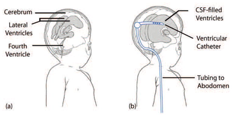
Illustration of hydrocephalus. (a) the ventricular system of a normal infant and (b) enlarged ventricles and an implanted shunt system. The ventricular catheter directs CSF from the ventricles to the the abdomen via the valve, tubing, and the distal catheter. Adapted from [1].
Hydrocephalus patients depend heavily on proper functioning of the shunt system, which consists of a ventricular catheter, a valve, and a distal catheter that drains excess CSF from the ventricles to the abdomen. The shunt system is regarded as the gold standard in treatment and management of hydrocephalus. Unfortunately, the shunt system, which is critical in hydrocephalus care, is plagued with a very high rate of failure. Clinical studies have revealed that up to 40% of shunts fail within the first year of implantation [2, 3], and 85% of patients with shunts undergo at least two or more shunt-revision surgeries within 10 years of initial implantation [4].
The high shunt failure-rate is compounded by the relatively high prevalence of hydrocephalus. The National Institute of Health estimates that as one in every 500 children in the US is diagnosed with hydrocephalus and each year estimated 400,000 shunt-related operations are performed each year in the US [5, 6]. The annual medical costs associated with the treatment of hydrocephalus thought to be greater than $1 billion [6].
The leading cause of shunt failure is the obstruction of the ventricular-catheter pores, which is caused by prolonged and slow accumulation of cellular adhesion [7]. Ventricular catheters contain a multitude of pores on its proximal end, through which CSF in the ventricles flows into the lumen of the shunt and ultimately into the abdomen of the patient. Due to various inflammatory and immune-specific responses as well as contributions from red blood and ependymal cells, the catheter pores become occluded over time [8–14]. Other potential causes of shunt failure include infection, tissue migration, and overdrainage, for which there have been considerable research to date with varying degrees of success [15–23]. While a number of catheter designs with different physical constraints and biomaterial approaches have been proposed over the past several decades, catheter occlusion still remains a significant problem in practice [7,19,20,24,25].
Our approach is to use local mechanical force to clear the cellular accumulation at the catheter pores. Microscale magnetic microactuators are well suited for this application for several reasons. First, microfabricated devices can be designed and fabricated on the same physical scale as that of the catheter pores (~1 mm). Second, the magnetic microactuators described here require no implanted power supply, control electronics, or wires. Lastly, magnetic microactuators can generate large out-of-plane movements with significant force, which is well-suited for disrupting or preventing biological accumulation. In the presence of strong magnetic fields, our torsional magnetic microactuators rotate about its mechanical suspension to physically sweep accumulated bio-debris from the catheter pores. Our hypothesis is that the microactuation will result in an open pore following each actuation sequence.
Other groups have also proposed using microfabrication technology for the treatment of hydrocephalus. These attempts include using wireless pressure sensors [26], electromagnetic micro-pumps [26,27], and micro-needles and valves [28]. Although these researchers have demonstrated feasibility of using microscale sensors and actuators for hydrocephalus management, none has yet addressed the core issue of cellular accumulation that leads to catheter failure.
Here we report on the initial development of torsional magnetic microactuators for the amelioration of hydrocephalus. Several versions of torsional designs were microfabricated and tested to evaluate the feasibility of using the magnetic actuators to cause sufficient physical agitation that can clear cellular accumulation. We have quantitatively assessed the efficacy of the magnetic microactuators and shown that our device can produce significant reduction in cellular accumulation. Finally, we evaluated the effect of fatigue on the mechanical robustness of the torsional magnetic microactuators. Successful implementation of our magnetic microactuators may lead to the next generation of ventricular catheters with a greater lifespan.
2. Design and Fabrication
2.1. Design and Theory of Torsional Magnetic Microactuators
The use of magnetic microactuators in biological fluids has been demonstrated in the past [29, 30]. Our early attempts to fabricate magnetic microactuators, however, were met with a few challenges. Our first-generation devices were related using a potassium-hydroxide (KOH) etch. Due to the rectangular design of the 1st-generation magnetic microactuators, testing of a wide range of actuator designs was limited by the fact that devices with very wide torsion beams (>60 μm) failed to fully release due to the slower etch rate of <111> planes of the single-crystal silicon (Figure 2, [31]). and the alignment of the beams in the <110> directions.
Figure 2.
(Left) Scanning electron micrograph of a fully released (torsion-beam width = 20 μm) device and (Right) an incompletely released non-functional microactuator (torsion-beam width = 80 μm).
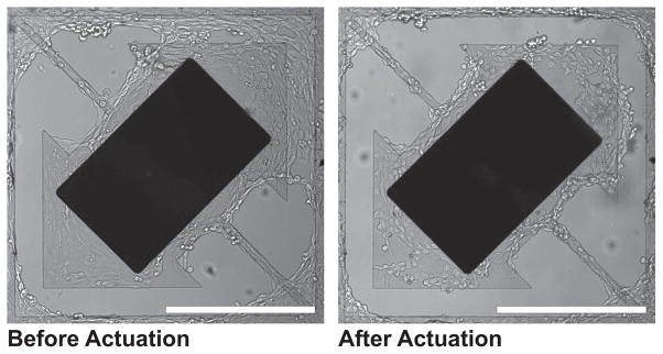
For the second-generation devices, we modified the design to overcome this issue by aligning the torsion beams in the <100> directions. In addition, we also modified the devices to have larger structural plate to facilitate cellular growth (Figure 3) We also modified the devices to have larger structural plate to facilitate cellular growth (Figure 3) [32]. Using these second-generation rectangular devices, we were able to qualitatively demonstrate that the cellular clearance is indeed possible using our torsional magnetic microactuators (Figure 4).
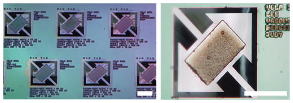
Figure 3.
Photographs of a portion of the microactuator array with 300×500×7 μm3 magnet volumes and 40-μm torsion beams and a 75-μm-wide gap. Scale bar = 400 μm.
Figure 4.
Cell clearing images of second-generation magnetic microactuator with 20-μm-wide torsion beams and a 75-μm-wide gap taken before and after actuation. Note the cellular clearance of cells grown over the gap on the upper right corner. Murine vascular smooth muscle cells (SV40LT-SMC Clone HEP-SA, #CRL-2018, ATCC, Manassas, VA, USA) were used. Scale bar = 400 μm.
Building upon our investigation of ventricular-catheter obstruction and our previous fabrication attempts, we designed a novel third-generation magnetic microactuators that are produced using deep reactive ion etching (DRIE) [33]. By using DRIE instead of anisotropic etching of silicon using KOH, the in-plane geometry of the devices had much greater flexibility (i.e., circular geometry, and complete freedom of torsion-beam width and orientation) (Figure 5). Since our ultimate goal is to incorporate the magnetic microactuators into implantable ventricular catheters, the circular geometry will be particularly useful for facilitating the integration of the magnetic microactuators into the circular pores of a ventricular catheter.
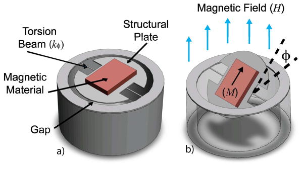
Figure 5.
3D illustrations of a round magnetic microactuator with torsion-beams: (a) without deflection and (b) under the influence of a magnetic field. The angle of device deflection is indicated by φ.
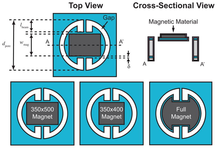
As can be seen in Figure 5a, the magnetic microactuator features a structural plate, which is anchored on two sides by torsion-beams. An electroplated nickel magnet is attached to the top of the structural plate to apply magnetic torque on the device. The top and side views of the actuator design are shown in Fig 6.
Figure 6.
Above: Top and cross-sectional view of the round torsional magnetic microactuators. Several key design parameters are noted. Below: Three magnet design variations are illustrated.
In the presence of a magnetic field, the torque generated by the ferromagnetic element causes the structural plate to rotate about the long axis of the torsion beams (Figure 5b). Assuming full magnetization of the ferromagnetic element, the angular rotation of the structural plate can be described by the following equation [30,34]
| (1) |
with angular rotation φ, magnet volume ν, induced magnetization vector M⃗, applied magnetic field vector H⃗, and the angular torsion-beam stiffness kφ. The angular stiffness of the torsion-beam is defined by [30]
| (2) |
with shape-dependent factor K, shear modulus G, polar moment of inertia J [35], residual beam stress σ, and the torsion-beam length lbeam. The shape-dependent factor K in our rectangular torsion beam can be expressed as [36]
| (3) |
with the torsion-beam thickness tbeam and width wbeam. To verify the effect of torsion-beam width and gap distance on the cell clearance, we created a 5 × 5 array of 25 microactuators on each die, which were comprised of a combination of gap distances (5, 10, 20, 40, and 80 μm) and torsion-beam widths (20, 40, 60, 80, 100 μm).
2.2. Design of the Ferromagnetic Element
As can be seen in Figure 6, the length of the beam and the width of the magnet is in a zero-sum relationship
| (4) |
with pore diameter dpore, torsion-beam length lbeam, magnet width wmag, and spacing δ.
The torsion-beam length is directly proportional to its stiffness as described by Equation 2. Simultaneously, the magnet width is linearly proportional to the angular rotation φ, as can be seen in Figure 5, given by Equation 1.
If we set the magnet length to be 500 μm, and set the spacing δ, magnetization M⃗, shape-dependent factor kbeam, shear modulus G, residual stress σ, and polar moment of inertia Jbeam to be constant values, we see that an optimum magnet width which generates the maximum deflection at a given magnetic field strength is found to be 380 μm (Equation 5).
| (5) |
Since the magnet needs to be circumscribed within the structural plate, increasing the width of the rectangle also decreases the magnet length. As such, we chose the magnet width to be 350 μm. Increasing the volume of the magnetic material increases magnetic torque and thus produces more deflection for a given magnetic field strength. To test the effect of angular deflection on cell clearance, one of three different magnet designs were implemented per die: a smaller magnet with a lower aspect ratio (350×400 μm2), a larger rectangular magnet with a higher aspect ratio (350×500 μm2), and an irregularly shaped maximum magnet volume for maximum magnetic torque (Figure 6). On a 100-mm-diameter substrate, a total of 16 dies were fabricated: four copies containing one of the three magnet designs, three copies of control devices without magnets, and a single die with empty pores to monitor the fabrication process.
2.3. Fabrication
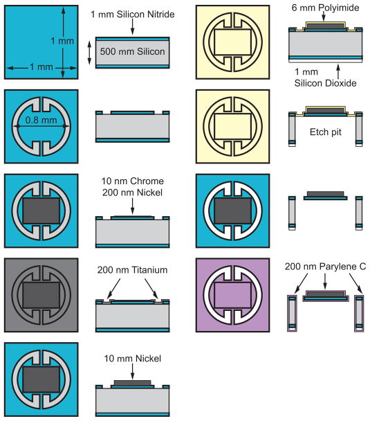
The torsional magnetic microactuators were fabricated using conventional microfabrication techniques on a 100-mm-diameter single-crystal <100> silicon wafer (TechGophers Corporation, Chino Hills, CA, USA). Figure 7 illustrates the top and cross-sectional views of the fabrication process for the round third-generation torsional magnetic microactuators. After cleaning and etching away native oxide using hydrofluoric acid (HF, Fisher Scientific International, Waltham, MA, USA), we conformally deposited a 1-μm-thick layer of low-stress silicon nitride using low-pressure chemical-vapor deposition (LPCVD, Tytan Furnace System, Tystar Corporation, Torrence, CA, USA). In the first photolithography step, the nitride was patterned with a thin photoresist layer (AZ 5214-E, Clariant Corporation, Somerville, NJ, USA) to define the boundaries for the structural features of the actuator. The nitride layer was then selectively etched using an Advanced Oxide Etcher (AOE, Multiplex Platform, Surface Technology Systems, Imperial Park, Newport, UK). The protective photoresist was subsequently etched away using a downstream plasma etcher (System One Stripper 105R, Matrix, Richmond, CA, USA).
Figure 7.
Microfabrication process of the round DRIE-released third-generation magnetic microactuators.
Next, we used AZ 5214-E photoresist in a second pattern that exposes areas of the wafer for the metal-adhesion process, which deposited a 10-nm thick layer of chromium and a 100-nm thick layer of nickel. The metal layers were deposited using an e-beam evaporator (Mark 40, CHA Industries, Fremont, CA, USA). Using a lift-off process, the metal layers were patterned. A 200-nm-thick titanium conduction layer was evaporated over the patterned metal layers to connect the chrome and nickel seed layers.
To electroplate the nickel ferromagnetic element, we defined a 10-μm-thick plating mold using a thick layer of photoresist (SPR 220-7.0, Shipley Company, Marlborough, MA, USA). We used a 90-s-long dip in a dilute (200:1) HF solution to etch away the titanium layers and expose the underlying nickel seed layer at the base of the photoresist mold. We then placed the wafer in a nickel-plating solution (1-M nickel sulfamate and 0.4-M boric acid) and passed a constant current density of 10 mA/cm2 to the seed layer for 25 min. After plating a 7-μm-thick nickel magnet, the photoresist mold was removed by rinsing the wafer successively in acetone, methanol, isopropanol, and finally in deionized water. The titanium conduction layer was then completely removed with a 2-min-long etch using the dilute HF solution.
To release the microactuators, we used a dry, fast, and deep silicon etch (FDSE III, Versaline, OC Oerlikon Balzers AG, Balzers, Liechtenstein). In order to etch through the entire 500-μm-thick wafer using the deep anisotropic etch, a 1-μm-thick layer of silicon dioxide was deposited on the backside of the wafer to serve as a hard mask. Following the backside deposition, 6 μm of polyimide (PI-2611, HD Microsystems, Cupertino, CA, USA) was deposited to the front-side of the wafer to serve as an etch stop for the release process.
Thick photoresist (SPR 220-7.0) was used again to pattern the backside and to define the regions for the release etch. A 6-min-long etch in the AOE defined both the silicon-dioxide and silicon nitride layers. To provide a smooth and clean surface for the DRIE process, the photoresist was fully removed prior to the release etch using the downstream plasma etcher. A 50-min-long, backside DRIE etch then removed the silicon substrate bulk and formed the pit below the microactuator. The polyimide etch stop was removed in three consecutive etches in the downstream plasma etcher, splitting 100-mm-diameter substrate into 16 dies, each containing an array of 25 devices. Finally, the devices were conformally coated with a biocompatible polymer, parylene C (poly-para-xylylene C, Specialty Coating System, Indianapolis, IN, USA). A completed device with maximum magnet volume is shown in Figure 8.
Figure 8.
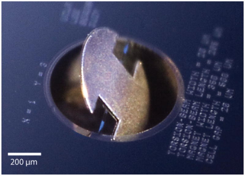
Digital photograph of a round magnetic microactuator in a deflected state. Schematic top view of device shown in Fig 5. Photograph taken by Jeffrey Tseng.
3. Device Characterization
3.1. Saturation Magnetization of Electroplated Nickel
We characterized the magnetic properties of the electrochemically-plated nickel magnet using a vibrating-sample magnetometer (Digital Measurement Systems, Westwood, MA, USA). A complete B - H loop was obtained and the saturation magnetization of the nickel magnet was measured to be 0.6 T.
3.2. Static Response
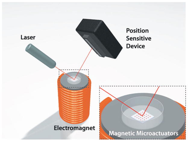
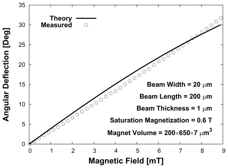
Next, we measured the angle of rotation produced by each microactuator as a function of known applied magnetic field. We quantified the angular deflection by recording the changes in position of a laser beam (Class IIIA, Alpec-Team Inc., Livermore, CA, USA) that was reflected off of the nickel surface of a magnetic microactuator. The laser-deflection experimental setup used for device characterization is illustrated in Figure 9. The values for the material properties of LPCVD SixNy, such as the elastic modulus (170 GPa) and the intrinsic stress (100 MPa), were obtained from literature for the theoretical deflection [34, 37]. A plot of the measured and theoretical deflections is shown in Figure 10.
Figure 9.
A 3D illustration of the laser-deflection setup. As the magnetic microactuator rotates at a given applied magnetic field, the position sensitive device captures the displacement of the laser-beam position.
Figure 10.
Theoretical and measured deflection and torque for an applied external magnetic field of a sample magnetic microactuators.
3.3. Dynamic Response
Dynamic magnetic behavior was also characterized to obtain actuation parameters for testing devices in a clinically relevant fluidic environment. The theoretical resonant frequency of each device in air Ωair can be expressed by
| (6) |
with the moment of inertia of the magnetic component including the structural-layer J, magnet and structural-layer mass mtotal, and structural-layer length lstruc.
Previous studies have shown that increasing the viscosity of the environment surrounding the MEMS actuators results in a decrease in resonant frequency and amplitude [38–42]. Since the fluid surrounding the device must be actuated along with the structural plates, the effective mass of the device is increased by an additional mass madded, which decreases the resonant frequency. The resonant frequency in fluid is given by
| (7) |
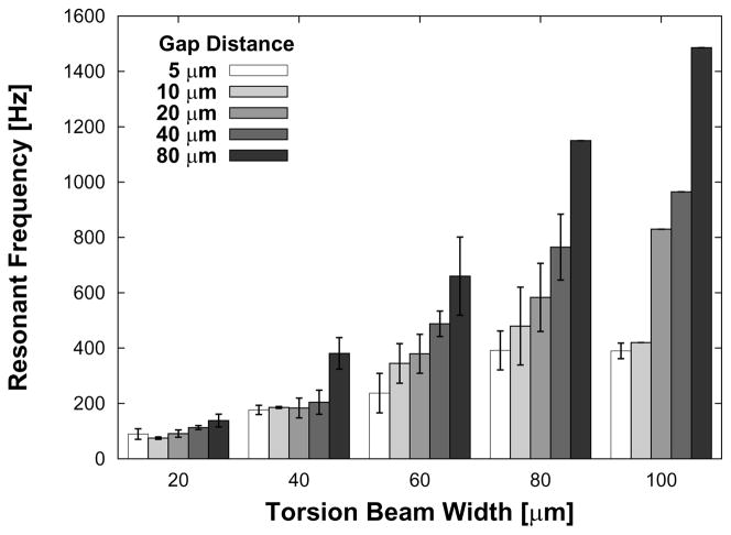
When tested in water, the devices tested produced resonant frequencies that spanned from 70 Hz to 1.5 kHz. As can be seen from the Equation 7, we expected beam stiffness, structural mass, and device length (gap distance) to directly affect resonant frequency in water. Figure 11 shows that the resonant frequency does indeed increase with increasing beam width and also with increasing gap distance. This later result is expected because, for a given pore diameter, as the gap distance increases, the structural plate area decreases, which in turn reduces madded. A one-way ANOVA (STATA/IC 10, Stata Corp, College Station, TX, USA) confirmed the strong dependence of resonant frequency on beam width (p < 0.00001) and weaker dependence on gap distance (p = 0.0590).
Figure 11.
Plot of the range of resonant frequencies for all devices with 350×500×7 μm3 magnet volumes. The results are expressed as average ± s.d. See Table 1.
The theoretical quality factor Qair for devices tested in air is given by
| (8) |
with damping coefficient γ. Similarly, using the effective mass value, the theoretical quality factor for a device operated in water Qwater is given by
| (9) |
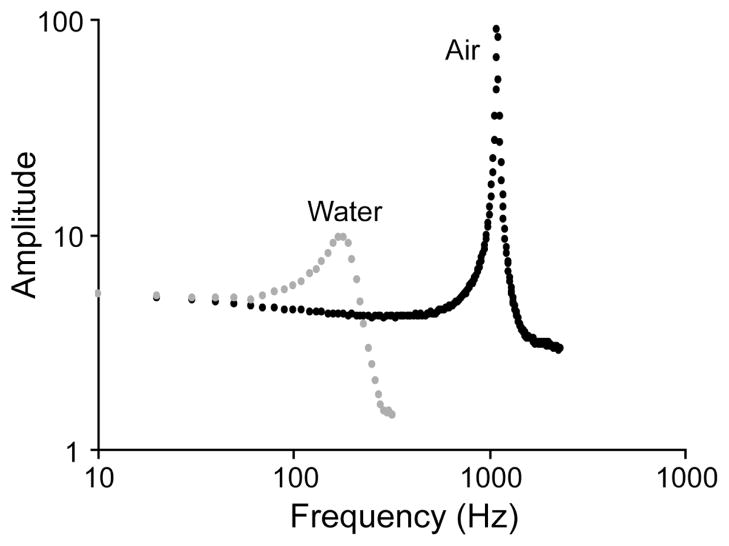
Using the data we collected, we determined the quality factor to be 600 in air and 5 in water (Figure 12).
Figure 12.
Plot of amplitude as a function of frequency for a device with 20-μm-wide torsion beams and a gap distance of 40 μm in air and also submerged in water. The resonant frequency is shown to be 180 Hz for water and 1.1 kHz for air.
3.4. Effect of Fatigue
To ensure reliable long-term operation of the magnetic microactuators, we subjected these round torsional microactuators to an accelerated testing protocol. One way of measuring the effect of fatigue in micromechanical structures is to compare the change in resonant frequencies before and after an extended actuation cycle [43,44]. To perform this study, we first measured the baseline frequency response of eight magnetic microactuators in air using a laser-deflecting setup (Figure 9). Devices were then divided into two groups: non-actuated control (n = 4) and actuated (n = 4). The resonant frequencies of the actuated-group devices were measured in water to determine the actuation frequency. Two devices from the actuated group were lost due to mishandling prior to the long-term actuation and the corresponding data were omitted.
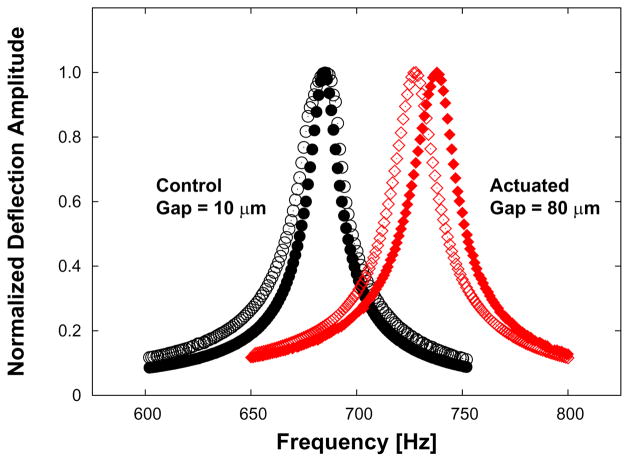
Both groups of devices were then submerged in body-temperature (37 °C) phosphate buffered solution (PBS) to mimic physiological conditions. Only the actuated-group devices experienced the ac magnetic field, which was driven at a frequency of 115 Hz and a magnetic field strength of 8 kA/m (~10 mT) in PBS. Since the experiment lasted 26 days, the actuators were put through >2.5 · 108 cycles. Figure 10 shows that the devices should deflect approximately 35 degrees at static magnetic field strength of 10 mT. Although the Ωwater of one actuated device was greater (152 Hz) than the actuation frequency, this device still fully deflects (Figure 11) at 115 Hz given the width of the resonance peak (Figure 12). After 26 days, all devices were removed from the PBS, rinsed, dried and re-characterized in air for their resonant frequencies. Figure 13 shows the ~2% increase in resonance frequency of an actuated device following >2.5 · 108 cycles.
Figure 13.
The effect of long-term actuation on resonant frequency. Dynamic responses in air of control (non-actuated) versus actuated devices are shown before (no-fill) and after (filled) actuation. Note the close overlap of frequency response in a sample control device compared to the shifted frequency response in an actuated device. See Table 2. The change in resonance frequency is ~2%.
4. Cell-Removal Capability
The success of our magnetic microactuators will be determined by the ability of actuation to clear cellular material. As such, we sought to quantify the cell-removal capability of our devices. The cell types that contribute to occlusion of catheter pores ought to be used to measure the cell-removal capacity of our devices. With our previous generation of devices, we evaluated the three readily available adherent cell types: Chinese Hamster Ovary cells (CHO-K1, #CCL-61, American Type Culture Collection, Manassas, VA, USA), adipose-derived stem cells, and normal human astrocytes. Unfortunately, these three types of cells, which were chosen to grow over our prototype microactuators, did not proliferate as expected.
After investigating various cell lines, we chose the murine vascular smooth muscle cell line (SV40LT-SMC Clone HEP-SA, #CRL-2018, American Type Culture Collection, Manassas, VA, USA) for its ability to adhere and proliferate on unconventional surfaces, such as parylene C. Although vascular smooth muscle cells are typically not found within the CSF of hydrocephalus patients, we can obtain critical information regarding the performance of our device against these aggressively growing adherent cells.
We used jet impingement as described by Deshpande and Vaishnav [45] to determine that the adhesion strength for the smooth muscle cells grown on parylene-C was identical to that of MC3T3 fibroblast cells (MC3T3-E1 Subclone 4, #CRL-2593, American Type Culture Collection, Manassas, VA, USA) grown on conventional polystyrene dishes (Table 3). We stained the live cells with a fluorescent dye (5(6)-CFDA, SE(5-(and-6)-Carboxyfluorescein diacetate, succinimidyl ester), Biotium, Inc., Hayward, CA, USA) to allow us to quantify the density of living cells through imaging.
Table 3.
Cell-adhesion forces represented by shear force for smooth muscle cells on parylene and fibroblasts on polystyrene (n = 12 for both cell types). Shear forces are listed as average ± s.d.
| Cell Line and Substrate Material | Lesion Radius [μm] | Shear Force [Pa] |
|---|---|---|
| SV40LT-SMC on parylene-coated SixNy | 0.9234 | 274.92 ± 48.20 |
| MC3T3-E1 on tissue-culture polystyrene | 0.9661 | 244.95 ± 26.45 |
To facilitate cellular adhesion, each array of devices was placed into a separate 35-mm-diameter tissue culture dish and covered with 2 ml of warm (37 °C) fresh frozen plasma (FFP) for 12-hr-long prior to cellular experiment. We then trypsinized the cells and isolated them with fresh media to be seeded onto the devices. An array of devices was then removed from the FFP bath and placed into a new tissue-culture dish. After loading 2 ml of fresh media containing one of the adherent cell types onto the center of the device array, we incubated the device in a sterile incubator for further cellular proliferation.
Following successful cellular seeding and proliferation, the devices were individually imaged with an illumination wavelength that excites green fluorescent protein. To confirm cell adhesion to the device surface, the media was gently exchanged prior to imaging. By measuring the surface area over the microactuator that displayed fluorescence, we were able to calculate a baseline cell density using image analysis software (Metamorph 6.3, Molecular Devices, Sunnyvale, CA, USA), which we compared to the cell density after actuation. As a result, this change in cell density represents a quantified value for cell clearance. The devices were then actuated at a magnetic field of 17.8 kA/m for either 30, 45, or 60 min at a frequency of 100 Hz, which is below the resonant frequency of most devices. We then imaged each actuator and observed the effect of actuation by comparing the cell density over the devices before and after actuation.
We tested a total of 56 actuated devices with varying gap distances, beam widths, and magnet volumes, and a total of 51 control devices with varying beam widths and gap distances, but no magnetic components. Devices with broken beams and structural plates were removed from the experiment. Additionally, arrays with low cell density (<15% initial cell coverage) were also omitted from the testing process. Lastly, those images with floating cell debris, which caused inaccurate intensity readings, were eliminated from the analysis.
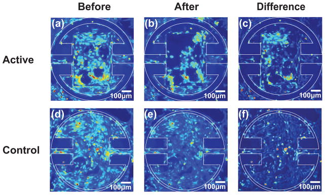
We were able to achieve full confluency on the majority of the microactuators and cellular bridging across the gap distance on 18 devices. Figure 14 shows that actuation pulls the cellular layer away from the side wall. We actuated the devices with a magnetic field strength of 17.8 kA/m at 100 Hz. The difference maps illustrating the effect of actuation are shown in Figure 15.
Figure 14.
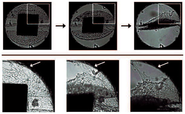
Images of a round torsional magnetic microactuator with 40-μm-wide torsion beams, 350×400×7 μm3 magnet volume, and a 5-μm-wide gap taken over the course of actuator deflection. The top diagram indicates the portion of the actuator shown in the bottom photograph sequence. Actuation was achieved using a hand-held magnet to facilitate imaging. Note that the cellular layer bridging the gap was torn from the side wall, as indicated by the white arrow.
Figure 15.
Images of a round magnetic microactuator with 100-μm-wide torsion beams, 350×500×7 μm3 magnet volume, and a 40-μm-wide gap taken (a) before actuation and (b) after actuating for 30 min at 100 Hz in a magnetic field of 17.8 kA/m. The difference map showing the areas where cells were cleared is shown in (c). Control devices with 60-μm-wide torsion beams and a 5-μm-wide gap were imaged (d) before actuation and (e) after actuating for 30 min at 100 Hz in a magnetic field of 17.8 kA/m. The difference map is shown in (f). Note that actuation of magnetic devices has reduced the overall cellular density, particularly in the top left corner (c) of the actuator.
As expected, the actuated devices (n = 56) with magnetic components decreased the cell density more effectively than the non-actuated control devices (n = 51) (Figure 16(a), Table 4). One-way ANOVA analysis indicated that the improved cell clearance due to actuation is statistically significant (p < 0.0001). Additionally, the effectiveness of cell removal increased in a statistically significant manner with increasing actuation duration (p < 0.0004). Figure 16(b) shows a comparison between experimental and control trials for devices that were driven for 30, 45, or 60 min (Table 5). The effect of actuator-deflection magnitude on cell clearance is shown on Figure 16(c). The collected data indicates that the cell-clearing increased with greater angular deflection in a statistically significant manner (p < 0.0001). A Tukey-Krammer pairwise post-hoc analysis (STATA/IC 10, Stata Corp, College Station, TX, USA) was performed to compare cell clearance between each group. The results confirmed that a deflection of at least 30° is required to produce a significant additional clearance compared to the non-actuated control. Comparisons between larger angular deflection groups were found to be non-significant. The effects of gap distance and beam width on cell clearance were also non-significant (p = 0.2119 and p = 0.5). No other significant interactions were found between variables.
Figure 16.
Effects of various experimental conditions on cellular deflection. Left: comparison between non-actuated control group versus actuated devices. Center: the effect of actuation duration on cell clearance. Right: the cell clearance as a function of deflection magnitude of devices. The clearance data is expressed as average ± s.d.
Table 4.
The number of devices tested for the effect of actuation duration.
| Time [min] | Control | Actuated |
|---|---|---|
| 30 | 17 | 25 |
| 45 | 29 | 19 |
| 60 | 5 | 12 |
Table 5.
The number of devices tested for the effect of angular deflection.
| Deflection [deg] | n |
|---|---|
| 0 | 51 |
| 20–30 | 13 |
| 30–40 | 15 |
| 40–60 | 18 |
| 60–90 | 10 |
5. Discussion and Conclusions
Here we reported on the design, fabrication, and testing of several iterations of magnetic microactuators for use in a cellular environment as the first step towards developing a MEMS-enabled self-clearing hydrocephalus catheter. We have experimentally demonstrated that the static and dynamic response of the microfabricated torsional actuators behave in accordance to theory. The dynamic behaviors of the microactuators were also characterized in a biologically-relevant fluid environment. As expected, the devices experienced a heavy amount of damping. Understanding the dynamic response of the magnetic microactuators in fluid is critical for the development of appropriate actuation strategies for implanted devices.
The effect of long-term actuation was quantified by measuring the changes in resonant frequencies of devices. After >2.5 · 108 cycles of actuation, the resonant frequency of actuated devices increased only marginally (<2%). However, it is unclear as to how many total cycles of actuation each devices will undergo in a clinical setting. If we assume 30 min of weekly actuation to keep the catheter pores open, the device will experience approximately 107 cycles in one year with the actuation frequency of 115 Hz. On average a typical patient undergoes two revision surgeries in a 10-year-long period [7]. Therefore, the total number of actuation to ensure that the pores remain open for the 10-year-period is then ~108 cycles.
There are, however, a few caveats of our experimental methodology that should be taken into consideration. First, these devices were actuated in PBS without any cells or proteins. Second, implanted devices would experience a continuous flow of CSF through the pore. In our experiment, the devices were actuated in a static PBS bath. It is unknown as to what effect the presence of biological material and a persistent low-speed fluid flow will have on these microactuators in the long term. Lastly, we made an assumption in our experimental design that a lower-than-resonant actuation-frequency should still fully deflect the device given the frequency response of a water damped device (Figure 12). It would be beneficial to experimentally confirm that the devices with various geometry do indeed deflect fully as expected at a chosen actuation frequency. Since these additional factors may modify the induced stress on the devices in a chronic term, further experiments with more samples may be necessary to fully assess the effect of fatigue in a more clinically relevant circulating in vitro setup.
Our cell-clearing results share similar concerns. The results indicate that the magnetically actuated microdevices are capable of producing the forces required to remove a large fraction of adherent cells grown over the microactuator surface. However, non-actuated control devices have also demonstrated cell-clearance ability to a certain degree (Figure 16(a)). This may be due to the long period of time during which the samples were taken out of the incubator for experiments. During this time, the cells may have become stressed due to the non-hospitable external environment. The potential impact of the prolonged exposure may be seen in Figure 16. We can see that the control group for 60-min-long actuation had greater cell clearance compared to the shorter actuation-duration control groups.
The fluorescent imaging process may also have deteriorated cell condition. The experimental protocol required images of each device pre- and post-actuation, which prolonged the exposure time. In addition, the frequent handling of devices from the incubator to the fluorescent microscope to the electromagnet and back to the microscope may have resulted some unwanted cell clearance. It may be interesting to compare the cell-clearance data obtained from cells that are kept inside of the incubator for the entire duration of the experiment to evaluate the potential impact of external exposure and handling.
Despite these concerns, our results clearly demonstrate that the magnetically actuated devices are capable of producing sufficient forces required to remove a large fraction of adherent cells grown over the device surface. We have shown that a prolonged actuation duration may significantly improve cell clearance (Figure 16(b)). We have also shown that angular deflections of > 30° may generate greater cell clearance. The differences between > 30° and larger deflection groups were not significant, suggesting that there may be an optimum deflection magnitude.
Moreover, our results highlight the effect of certain device characteristics on cell-clearing performance. First, we reported that the cell clearance is not significantly related to the gap distance between the structural plate and the side wall of the device, which may be due to limited range of gap distances tested. Thus, it would be interesting to test greater range of gap distances that generates no cell clearance. Although additional experiments are needed to fully assess the effect of gap distance, our present results tentatively suggest that there may be an optimum gap distance that results in maximum clearance and CSF flow. Second, we have also found that the torsion-beam width had little effect on cell clearance. From the static angular deflection equation (1), we can see that increasing beam width should increase mechanical stiffness kφ of the beam and produce a smaller angular deflection. Conversely, the narrower beam results in a greater angular deflection per given magnetic field even though the beam itself may be more prone to structural damage. Thus, additional data on the effect of fatigue across various beam widths may be necessary to determine the optimum torsion-beam width that results in high angular deflection and great mechanical robustness.
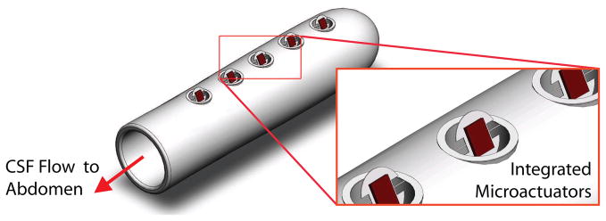
In the future, we plan to evaluate the cell-clearing performance of the magnetic microactuators in a more clinically relevant setup. A circulating in vitro setup that mimics the continuous flow of CSF through the ventricles may provide more robust cell-clearance and long-term fatigue data. Other plans include designing less obtrusive magnetic microactuators, evaluating magnetic resonance imaging safety, and integrating the microactuators into implantable catheters (Figure 17). Once we demonstrate the cell-clearing capabilities in a more complex in vitro model, we plan to replicate these results in one of many existing in vivo models using the proposed MEMS-enabled ventricular catheters [46–49]. By producing a self-clearing catheter, our goal is to greatly decrease the probability of biological shunt obstruction. In turn, we hoped that patients with MEMS-enabled self-clearing shunt systems will require fewer replacement surgeries, face less risk and stress associated with surgeries, and maintain a greatly improved quality of life.
Figure 17.
A 3D illustration of the proposed MEMS-enabled ventricular catheters. Note that the integrated microactuators are shown in actuated state.
Table 1.
The number of devices tested for resonant frequencies.
| Beam Width [μm] | ||||||
|---|---|---|---|---|---|---|
| 20 | 40 | 60 | 80 | 100 | ||
| Gap [μm] | 5 | 2 | 2 | 3 | 6 | 3 |
| 10 | 3 | 2 | 5 | 4 | 4 | |
| 20 | 4 | 4 | 4 | 3 | 2 | |
| 40 | 3 | 2 | 3 | 3 | 1 | |
| 80 | 2 | 1 | 1 | 1 | 1 | |
Table 2.
The effect of long-term actuation. Note that the Ωwater were not measured for the control devices. The beam dimensions were identical for each listed device (beam width = 20μm, beam length = 205μm, beam thickness = 1μm).
| Gap [μm] | Ωwater [Hz] | Ωair [Hz] | Δ[%] | ||
|---|---|---|---|---|---|
| Pre | Post | ||||
| Actuated Control | 80 | - | 452.8 | 450.6 | −0.49 |
| 40 | - | 492 | 491.8 | −0.04 | |
| 20 | - | 559 | 561 | 0.36 | |
| 10 | - | 685 | 686.4 | 0.2 | |
| 80 | 152 | 726.4 | 738 | 1.6 | |
| 20 | 115 | 662 | 676.6 | 2.21 | |
Acknowledgments
This work is supported by the UCLA NeuroEngineering Training Program (NSF IGERT 9972802), the NIH National Health, Lung, and Blood Institute NRSA Fellowship (F31HL093994), the NIH National Institute of Neurological Disorders and Stroke NRSA Fellowship (F31NS05024), Medtronic, Inc., the UC Discovery Program (BIO-ELE04-1033), and the STARS-Kids Foundation. The authors would like to thank Brian Matthews, Ph.D. for his expertise in the development of the microfabrication process, and the UCLA Statistical Consulting Services for their assistance with data analysis.
References
- 1.Spina Bifida and Hydrocephalus Association of Nova Scotia. Hydrocephalus Information Page. [Google Scholar]
- 2.Pollack I, Albright A, Adelson P. A randomized, controlled study of a programmable shunt valve versus a conventional valve for patients with hydrocephalus. Neurosurgery. 1999;45:1399–1411. doi: 10.1097/00006123-199912000-00026. [DOI] [PubMed] [Google Scholar]
- 3.Kestle J, et al. Long-term follow-up date from the shunt design trial. Pediatric Neurosurgery. 2000;33:230–236. doi: 10.1159/000055960. [DOI] [PubMed] [Google Scholar]
- 4.Choux M, Di Rocco C, Hockley AD, Walker ML, editors. Pediatric Neurosurgery. Churchill Livingstone; 1999. [Google Scholar]
- 5.National Institute of Neurological Disorders and Stroke. NINDS Hydrocephalus Information Page. [Google Scholar]
- 6.Hydrocephalus Association. Treatment of Hydrocephalus. [Google Scholar]
- 7.Drake JM, Sainte-Rose C, editors. The Shunt Book. Blackwell Science; Cambridge: 1995. [Google Scholar]
- 8.Koga H, Mukawa J, Nakata M, Sakuta O, Higa Y. Analysis of retained ventricular shunt catheters. Neurologia Medico-Chirurgica (Tokyo) 1992;32(11):824–828. doi: 10.2176/nmc.32.824. [DOI] [PubMed] [Google Scholar]
- 9.Snow RB, Kossovsky N. Hypersensitivity reaction associated with sterile ventriculoperitoneal shunt malfunction. Surgical Neurology. 1989;31(3):209–214. doi: 10.1016/0090-3019(89)90119-5. [DOI] [PubMed] [Google Scholar]
- 10.Schoener WF, Reparon C, Verheggen R, Markakis E. Evaluation of shunt failures by compliance analysis and inspection of shunt valves and shunt materials using microscopic or scanning electron microscopic techniques. In: Matsumoto S, Tamaki N, editors. Hydrocephalus: Pathogenesis and Treatment. Springer-Verlag; New York: 1991. pp. 452–472. [Google Scholar]
- 11.Kossovsky N, Snow RB. Clinical-pathological analysis of failed central nervous system fluid shunts. Journal of Biomedical Materials Research. 1989;23(A1):73–86. doi: 10.1002/jbm.820231308. [DOI] [PubMed] [Google Scholar]
- 12.Bruni JE, Del Bigio MR, Clattenburg RE. Ependyma: Normal and pathological. a review of literature. Brain Research. 1985;356(1):1–19. doi: 10.1016/0165-0173(85)90016-5. [DOI] [PubMed] [Google Scholar]
- 13.Brydon HL, Bayston R, Hayward R, Harkness W. The effect of protein and blood cells on the flow-pressure characteristics of shunts. Neurosurgery. 1996;38(3):498–504. doi: 10.1097/00006123-199603000-00016. [DOI] [PubMed] [Google Scholar]
- 14.Del Bigio MR. Biological reactions to cerebrospinal fluid shunt devices: a review of the cellular pathology. Neurosurgery. 1998;42(2):319–325. doi: 10.1097/00006123-199802000-00064. [DOI] [PubMed] [Google Scholar]
- 15.Bayston R, Bhundia C, Ashraf W. Hydromer-coated catheters to prevent infection? Journal of Neurosurgery: Pediatrics. 2005;102:207–212. doi: 10.3171/jns.2005.102.2.0207. [DOI] [PubMed] [Google Scholar]
- 16.Bertrand WJ. Shunt infection. Journal of Neurosurgery: Pediatrics. 2005;103 doi: 10.3171/ped.2005.103.3.0293. [DOI] [PubMed] [Google Scholar]
- 17.Kang JK, Lee IW. Long-term follow-up of shunting therapy. Child Nervous System. 1999;15:711–717. doi: 10.1007/s003810050460. [DOI] [PubMed] [Google Scholar]
- 18.Bierbrauer KS, Storrs BB, McLone DG, Tomita T, Dauser R. A prospective, randomized study of shunt function and infections as a function of shunt placement. Pediatric Neurosurgery. 1990;16:287–291. doi: 10.1159/000120544. [DOI] [PubMed] [Google Scholar]
- 19.Haase J, Weeth R. Multiflanged ventricular catheter for hydrocephalic shunts. Acta Neurochirugica (Wien) 1976;33:213–218. doi: 10.1007/BF01886670. [DOI] [PubMed] [Google Scholar]
- 20.Richards H, Seeley H, Pickard J. Do antibiotic-impregnated shunt catheters reduce shunt infection? data from the uk shunt registry. 50th Annual Meeting of the Society for Research into Hydrocephalus and Spina Bifida; Cambridge, United Kingdom. August 2006. [Google Scholar]
- 21.Kestle JR, Drake JM, Cochrane DD, Milner R, Walker ML, Abbott R, 3rd, Boop FA. Endoscopic shunt insertion trial participants: Lack of benefit of endoscopic ventriculoperitoneal shunt insertion: A multicenter randomized trial. Journal of Neurosurgery. 2003;98:284–290. doi: 10.3171/jns.2003.98.2.0284. [DOI] [PubMed] [Google Scholar]
- 22.Drake JM, Kestle JR, Milner R, Cinalli G, Boop F, Piatt J, Jr , Haines S, Schiff SJ, Cochrane DD, Steinbok P, MacNeil N. Randomized trial of cerebrospinal fluid shunt valve design in pediatric hydrocephalus. Neurosurgery. 1998;43:293–303. doi: 10.1097/00006123-199808000-00068. [DOI] [PubMed] [Google Scholar]
- 23.Kestle JRW, Walker ML. A multicenter prospective cohort study of the strata valve for the management of hydrocephalus in pediatric patients. Journal of Neurosurgery: Pediatrics. 2005;102:141–145. doi: 10.3171/jns.2005.102.2.0141. [DOI] [PubMed] [Google Scholar]
- 24.Ventureyra EC, Higgins MJ. A new ventricular catheter for the prevention and treatment of proximal obstruction in cerebrospinal fluid shunts. Neurosurgery. 1994;34(5):924–926. doi: 10.1227/00006123-199405000-00025. [DOI] [PubMed] [Google Scholar]
- 25.Black C, Resau J, West R, Grever W, Hlady V, McAllister JP., II Are we implanting catheters that facilitates shunt failure?. 52nd Annual Meeting of the Society for Research into Hydrocephalus and Spina Bifida; Providence, Rhode Island, USA. June 2008. [Google Scholar]
- 26.Yoon HJ, Jung JM, Jeong JS, Yang SS. Microdevices for a cerebrospinal fluid (csf) shunt system. Sensors and Actuators A. 2004;110:68–76. [Google Scholar]
- 27.Moranti E, Pignatel GU. Microfluidics for the treatment of the hydrocephalus. Proceedings of the 1st International Conference on Sensing Technology; Palmerston North, New Zealand. November 2005. [Google Scholar]
- 28.Emam M, Abashiya Y, Chareunsack B, Skordos J, Oh J, Choi Y, Kralick F, Noh H. A novel microdevice for the treatment of hydrocephalus: Design and fabrication of an array of microvalves and microneedles. Microsystems Technology. 2008;14:371–378. [Google Scholar]
- 29.Judy JW, Muller RS, Zappe HH. Magnetic microactuation of polysilicon flexure structures. Journal of Microelectromechanical Systems. 1995;4(4):162–169. [Google Scholar]
- 30.Judy JW, Muller RS. Magnetic microactuation of torsional polysilicon structures. Sensors and Actuators A (Physical) 1996;A53:392–396. [Google Scholar]
- 31.Lee S, Vasquez DJ, Bergsneider M, Judy JW. Magnetic microactuators for MEMS-enabled ventricular catheters for hydrocephalus. Proceedings of the 28th Annual Conference of the IEEE Engineering in Medicine and Biology Society; New York City. Aug. 30-Sep. 3, 2006; [DOI] [PubMed] [Google Scholar]
- 32.Lee S, Bergsneider M, Judy JW. Magnetic microactuators for MEMS-enabled ventricular catheters for hydrocephalus. Proceedings of the 3rd International Conference of the IEEE Engineering in Medicine and Biology Society Conference on Neural Engineering; Kohala Coast, HI. May 2–5, 2007; [DOI] [PubMed] [Google Scholar]
- 33.Lee S, Pinney JR, Khialeeva E, Bergsneider M, Judy JW. Functional evaluation of magnetic microactuators for removing biological accumulation: An In Vitro study. Proceedings of the 30th Annual Conference of the IEEE Engineering in Medicine and Biology Society; Vancouver, BC, Canada. August 20–24, 2008; [DOI] [PubMed] [Google Scholar]
- 34.Judy JW, Muller RS. Magnetically actuated, addressable microstructures. IEEE Journal of Microelectromechanical Systems. 1997;6:249–256. [Google Scholar]
- 35.Roark RJ. Roark’s Formulas for Stress and Strain. McGraw-Hill; New York: 1989. [Google Scholar]
- 36.Timoshenko SP, Goodier JN. Theory of Elasticity. 3. McGraw-Hill; New York: 1970. [Google Scholar]
- 37.Edwards RL, Coles G, Sharpe WN., Jr Comparison of tensile and bulge tests for thin-film silicone nitride. Experimental Mechanics. 2004;44(1):49–54. [Google Scholar]
- 38.Maali A, Hurth C, Boisgard R, Jai C, Choen-Bouhacina T, Aimé J. Hydrodynamics of oscillating atomic force microscopy cantilevers in viscous fluids. Journal of Applied Physics. 2005;97:074907. [Google Scholar]
- 39.Rollier AS, Faucher M, Legrand B, Collard D, Buchaillot L. Electrostatic actuators operating in liquid environment: Suppression of pull-in instability and dynamic response. Proceedings of the Symposium on Design, Test, Integration and Packaging of MEMS and MOEMS; Rome, Italy. April 2006. [Google Scholar]
- 40.Zhang W, Turner K. Frequency dependent fluid damping of micro/nano flexural resonators: Experiment, model and analysis. Sensors and Actuators A: Physical. 2007;134:594–599. [Google Scholar]
- 41.Dareing DWFT, Thundat T. Effective mass and flow patterns of fluids surrounding microcantilevers. Ultramicroscopy. 2006;106:780–794. doi: 10.1016/j.ultramic.2005.11.011. [DOI] [PubMed] [Google Scholar]
- 42.Sader JE. Frequency response of cantilever beams immersed in viscous fluids with applications to the atomic force microscope. Journal of Applied Physics. 1998;84:64–76. [Google Scholar]
- 43.Brown SB, Van Arsdell W, Muhlstein CL. Material reliability in mems devices. Proceedings of the 1997 International Conference on Solid-State Sensors and Actuators; Chicago, IL. June 1997. [Google Scholar]
- 44.Chuang WH, Fettig R, Ghodssi R. Nano-scale fatigue study of LPCVD silicon nitride thin films using a mechanical-amplifier actuator. Journal of Micromechanical and Microengineering. 2007;17:938–944. [Google Scholar]
- 45.Deshpande MD, Vaishnav RN. Submerged laminar jet impingement on a plane. Journal of Fluid Mechanics. 1982;114:213–236. [Google Scholar]
- 46.Kohn DF, Chinookoswong N, Chou SM. Animal model of human disease. congentical hydrocephalus. Am J Pathol. 1984;114(1):184–185. [PMC free article] [PubMed] [Google Scholar]
- 47.McAllister JP, II, Maugans TA, Shah MV, Truex RC., Jr Neuronal effects of experimentally induced hydrocephalus in newborn rats. Journal of Neurosurgery. 1985;63(5):776–783. doi: 10.3171/jns.1985.63.5.0776. [DOI] [PubMed] [Google Scholar]
- 48.Oi S, Sato O, Yamada H, Matsumoto S. Experimental models of congenital hydrocephalus and comparable clinical problems in the fetal and neonatal periods. Child’s Nervous System. 1996;12:292–302. doi: 10.1007/BF00301016. [DOI] [PubMed] [Google Scholar]
- 49.Krishnamurthy S, Li J, Schultz L, McAllister J., II Intraventricular infusion of hyperosmolar dextran induces hydrocephalus: a novel animal model of hydrocephalus. Cerebrospinal Fluid Research. 2009;6(1):16. doi: 10.1186/1743-8454-6-16. [DOI] [PMC free article] [PubMed] [Google Scholar]


