

Abstract
In this study, a two part bone tissue engineering scaffold was investigated consisting of a solid poly(propylene fumarate) (PPF) intramedullary rod for mechanical support surrounded by a porous PPF sleeve for osseointegration and delivery of poly(DL-lactic-co-glycolic acid) (PLGA) microspheres with adsorbed recombinant human bone morphogenetic protein-2 (rhBMP-2). Scaffolds were implanted into critical size rat segmental femoral defects with internal fixation for 12 weeks. Bone formation was assessed throughout the study via radiography, and following euthanasia via micro-CT and histology. Mechanical stabilization was evaluated further via torsional testing. Experimental implant groups included the PPF rod alone and the rod with a porous PPF sleeve containing PLGA microspheres with 0, 2, or 8 μg of rhBMP-2 adsorbed onto their surface. Results showed that presence of the scaffold increased mechanical stabilization of the defect, as evidenced by the increased torsional stiffness of the femurs by the presence of a rod compared to the empty defect. Although the presence of a rod decreased bone formation, the presence of a sleeve combined with a low or high dose of rhBMP-2 increased the torsional stiffness to 2.06 ± 0.63 N·mm and 1.68 ± 0.56 N·mm, respectively, from 0.56 ± 0.24 N·mm for the rod alone. The results indicate that, while scaffolds may provide structural support to regenerating tissues and increase their mechanical properties, the presence of scaffolds within defects may hinder overall bone formation if they interfere with cellular processes.
Keywords: Bone Tissue Engineering, Bone Morphogenetic Protein, Bone Regeneration, Intramedullary Rod, Composite Scaffold
1.1 Introduction
Despite the inherent healing capacity of bone tissue, segmental defects remain a significant clinical challenge and often result in non-union.[1] Current standard of care relies on the use of stabilization with plates or rods and bone regeneration through the use of bone grafts or flaps. However, this strategy has inherent disadvantages with donor site morbidity and subsequent removal of stabilization hardware or lifetime placement.[2] While many other bone regeneration strategies have been investigated, many do not consider stabilization of segmental long bone defects in combination with regeneration and thus still require fixation. However, there are strategies in tissue engineering aiming to address these two issues simultaneously, and commonly include the use of a strong scaffold material with or without cells and/or growth factors to promote osteogenesis.[3–6]
In these strategies, the solid scaffold serves as the stabilization of the defect until the regenerated bone can sufficiently support the load. Loading of long bones varies by location but can be as much as 45 MPa with simple movements.[7] To support such loads, mechanically strong materials, such as ceramics and polymers, must be used.[4–6, 8–11] Among those investigated, poly(propylene fumarate) (PPF) is a biodegradable linear polyester with many unsaturated double bonds capable of crosslinking and it has been shown to be biocompatible[12–15] and osteoconductive.[5, 13–16] In addition to material selection, design issues such as scaffold porosity, shape, and architecture can all play a significant role in the tissue response, such that porosity is necessary for bone-scaffold integration and has significant effects on osteoconductivity.[17–19] Studies have previously shown that while solid PPF has mechanical characteristics similar to those of bone, porous PPF, commonly used in tissue engineering strategies, decreases the mechanical strength of the scaffold with increasing porosity.[4, 8] Strategies to address stabilization and bone regeneration have typically employed a solid and porous composite structure or a solid structure with degradable porogens to induce porosity.[20, 21] In a study by Kempen et al., a PPF intramedullary rod embedded with poly(DL-lactic-co-glycolic acid) (PLGA) microparticles for growth factor delivery was used.[21]
Intramedullary rods are used clinically to stabilize segmental defects and allow for bone growth and eventual union over the surface while maintaining mechanical support. Traditional metal intramedullary rods, which are commercially available and clinically used, are non-degradable and thus remain in the body for the patient’s lifetime but biodegradable systems allow for non-permanent fixation of these types of defects and could potentially mechanically stabilize segmental defects while allowing regeneration around them. For this stabilization to be sufficient, the mechanical properties of the intramedullary rod would be required to sustain the loads of the bone and be fixed to each segment of bone to prevent defect collapse and increase torsional stability.
In addition to scaffold design, delivery of drugs or bone healing promoting factors is commonly employed in tissue engineering strategies to accomplish several functions required for tissue regeneration.[22–27] A group of growth factors known as bone morphogenetic proteins (BMPs) have been studied extensively for applications related to bone regeneration. They have been shown to increase bone formation and are osteoinductive when delivered in a controlled manner.[25, 28, 29] Controlled release of BMPs has been studied with various release mechanisms, such as microparticle delivery systems.[21, 26, 29–38] Specifically, PLGA microparticles have been studied with recombinant human bone morphogenetic protein-2 (rhBMP-2) entrapped and adsorbed onto the surface.[38] Protein adsorption presents a delivery method that maximizes control of the factors at the time of scaffold fabrication, as the rhBMP-2 or other factor is not entrapped during the fabrication of the microparticles.
In this study, a long intramedullary rod of solid PPF was used to meet these mechanical requirements in a rat segmental femoral defect with additional internal fixation. Surrounding this rod, a porous PPF sleeve was used to increase bone integration and osteoconductivity and provide a structure for the delivery of rhBMP-2 adsorbed on PLGA microparticles. The solid intramedullary rod was hypothesized to enhance the mechanical stability with further enhancement by bone integration into the porous sleeve when present. Additionally, bone regeneration was hypothesized to be significantly affected by the delivery and dose of rhBMP-2.
2. Materials and methods
2.1 PPF Synthesis and Scaffold Fabrication
PPF was synthesized according to established methods.[39, 40] Molecular weight was confirmed via gel permeation chromatography (GPC) (Waters, Milford, MA) using polystyrene standards (Fluka, Switzerland). For this study, PPF with a number average molecular weight of 2900 and a polydispersity index of 1.4 was used. To make the solid PPF rods, a solution of PPF and N-vinyl pyrrolidone (N-VP, Sigma-Aldrich, St. Louis, MO) was combined in a 4:1 mass ratio and benzoyl peroxide (BP, Sigma-Aldrich, St. Louis, MO) was added in 2 wt% of the total PPF/N-VP solution. The solution was then centrifuged at 3000 rpm for 5 min in a Durafuge 100 centrifuge (Thermo Scientific, Asheville, NC), poured into 1.6 mm diameter poly(tetrafluoroethylene) (PTFE) molds and allowed to crosslink for 24 hr at 60°C. The rods were removed, cut to 8.5 mm in length and sterilized by ethylene oxide gas. For fabrication of porous scaffolds, the same PPF/N-VP/BP solution was prepared as above and combined with 80% w/w NaCl (300–500 μm). The resultant slurry was packed around a 1.6 mm diameter glass rod concentrically placed in a 3.5 mm diameter x 25 mm cylindrical PTFE mold. After packing the slurry to remove void spaces, the glass rod was removed and the resulting hollow cylinders were allowed to crosslink within the PTFE mold for 24 hr at 60°C. Subsequently, the NaCl/polymer cylinders were removed and cut with a diamond saw into 5 mm long sections. The salt porogen of the scaffolds was then leached in ddH2O for 1 week with daily water changes, freeze-dried, and sterilized with ethylene oxide gas.
2.2 Scanning Electron Microscopy
Scanning electron microscopy samples were prepared by placing longitudinally cut scaffolds on sample holders and sputter coating with approximately 20 nm of gold using a CrC-150 Sputter Coater (Torr International, New Windsor, NY). The top surfaces of scaffolds were viewed using a Quanta 400 Electron Microscope (FEI, Hillsboro, OR) operated at 30kV.
2.3 PLGA Microparticle Fabrication and rhBMP-2 Adsorption
PLGA microparticles were fabricated by solvent extraction in a water in oil in water emulsion as previously described.[38] Briefly, 1 g of PLGA (52 mol% DL-lactide:48 mol% glycolide, ~ 50,000 MW, Purac Biomaterials, Gorinchem, The Netherlands) was dissolved in 4 mL of methylene chloride. 500 μL of 0.1 wt% bovine serum albumin (BSA) in phosphate-buffered saline (PBS) was injected into the PLGA solution and vortexed for 60 s. Six mL of 0.3 wt% aqueous poly(vinyl alcohol) (PVA) solution was added and vortexed for 60 s. This solution was added to a stirring solution of 394 mL 0.3 wt% aqueous PVA solution and 400 mL of 0.2 vol% aqueous isopropanol solution. The extraction took place over 1 hr, when the microparticles were collected by centrifugation, rinsed with ddH2O three times, frozen and freeze-dried. Microparticles were sterilized with ethylene oxide gas, stored at −20°C and handled thereafter with aseptic techniques.
To create PLGA microparticles with rhBMP-2 (PeproTech, Rocky Hill, NJ), PLGA microparticles were allowed warm to room temperature and a sterile rhBMP-2 solution (0.65 mg rhBMP-2/mL PBS/BSA[0.1 wt%]) was adsorbed onto unloaded PLGA microparticles in a fluid:particle ratio of 0.8 mL/mg. This ratio provided complete wetting of the PLGA microparticles without fluid surplus. After 30 min adsorption time, microparticles were frozen at −20 C and lyophilized. Thereafter, microparticles were transferred into a new vial.
2.4 Composite Scaffold Preparation
Four PPF based scaffold groups and one empty group were included in the in vivo study. The groups are described in Table 1 and include: Group E: empty defect; Group R: solid PPF intramedullary rod; Group RSB: solid PPF intramedullary rod and porous PPF sleeve filled with 30 μL of 24% w/v Pluronic F-127 with 16.67 mg of blank PLGA microparticles; Group RSLo: solid PPF intramedullary rod and porous PPF sleeve filled with 30 μL of 24% w/v Pluronic F-127 with 12.5 mg of blank PLGA microparticles and 4.17 mg of rhBMP-2 adsorbed PLGA microparticles (corresponding to 2 μg of rhBMP-2 per scaffold based off of previous studies [21, 32, 41] and scaled to the volume of the defect); and Group RSHi: solid PPF intramedullary rod and porous PPF sleeve filled with 30 μL of 24% w/v Pluronic F-127 with 16.67 mg of loaded PLGA microparticles (corresponding to 8 μg of rhBMP-2 per scaffold based off of previous studies [21, 32, 41] and scaled to the volume of the defect). To fabricate the scaffolds prior to the surgical procedure, the porous sleeves were prewetted with an ethanol gradient whereby the scaffolds were wet with 100% ethanol then serially submerged and washed in solutions with 10% less ethanol in water and finally rinsed with sterile PBS three times. The prewet scaffolds were loaded with the Pluronic F-127 and PLGA suspension described above with a vacuum loading process by pipetting 15 μL of the mixture into the center of the sleeve and applying 100 mbar of vacuum, which was held for 15 s. This was repeated with an additional 15 μL of the Pluronic F-127 and PLGA suspension. The resultant 30 μL solution penetrated the scaffold. Each sleeve was incubated at 37°C for 10 min after the addition of the Pluronic F-127, to gel the solution within the pores. Figure 1a shows the assembled composite scaffold.
Table 1.
Abbreviations and sizes for all the groups in this study.
| Group | Description | n |
|---|---|---|
| C | Femur with no defect | 9 |
| E | Empty | 9 |
| R | Rod | 9 |
| RSB | Rod + sleeve loaded with blank PLGA | 9 |
| RSLo | Rod + sleeve loaded with 2 μg BMP-2 | 8 |
| RSHi | Rod + sleeve loaded with 8 μg BMP-2 | 9 |
Figure 1.
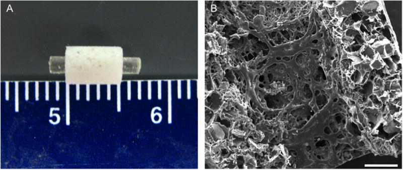
Structure of the PFF scaffold shown grossly in (A) where the rod is placed in the porous sleeve and microscopically through scanning electron microscopy shown in (B). Scale bar in (B) represents 500 μm.
2.5 Surgical Procedure
Scaffolds were placed in a critical size segmental femoral defect in a rat as previously described.[21, 42, 43] Fifty-three Lewis rats between 325 and 350 grams were purchased from Harlan Laboratories (Indianapolis, IN). All procedures complied with protocols approved by the Institutional Animal Care and Use Committee at Rice University.
Briefly, anesthesia was induced using 4% isoflurane in oxygen then maintained on 2% isoflurane in oxygen at 0.5 L/min using a nosecone. The rats were administered buprenorphine at 0.05 mg/kg intraperitoneally for perioperative analgesia and enrofloxacin at 10 mg/kg, subcutaneously for perioperative antimicrobial activity. The right hind leg of the rat was clipped free of hair and 100 μL of 0.25% bupivicaine with 1:200 of epinephrine were administered subcutaneously along the incision line. The rat was placed on a warming plate and the right leg was prepared sterilely. A 2.5 cm incision was made on the lateral side of the right leg centered between the hip and knee. The femur was exposed by blunt dissection and a polyethylene plate (22×3×4 mm) was fixed to the anterolateral side of the femur with 4 threaded Kirschner wires (Zimmer, Warsaw, IN). A 5 mm defect was created in the diaphysis of the femur using a cutting bur under irrigation of saline. The defect was irrigated to remove any residual bone dust and bone marrow contents. The two wires immediately adjacent to the defect were removed from the bone but remained in the plate as shown in Figure S1B. The segments of bone were rotated to allow placement of the scaffold, where one side of the rod, with or without the porous sleeve, was placed in the intramedullary canal of the proximal end of the defect and the opposite end was placed in the intramedullary canal of the distal end while simultaneously rotating the segments of bone back into alignment as shown in Figures S1C-E. This procedure allowed the placement of an 8.5 mm rod into the 5 mm defect. Once in place, the two wires were screwed back into the bone and the wound closed in two layers, muscle and skin, with 5-0 Vicryl sutures (Ethicon, Somerville, NJ). Each rat was given normal saline intraperitoneally at 10 mg/kg per hour of surgery and received a radiograph immediately postoperatively to ensure placement of the plate and alignment of the femur segments. Finally, each rat recovered in an elevated oxygen and warming environment until responsive and ambulating. All rats received buprenorphine every 12 hr at 0.05 mg/kg for 48 hr postoperatively and at 0.025 mg/kg for the next 48 hr. Additionally, each rat received radiographs every 3 weeks to assess bone formation throughout the study.[44]
All rats recovered immediately postoperatively and returned to ambulation. Of the 53 rats operated on, 9 rats experienced loosening of the plate more than 3 days post-operatively. These animals were euthanized at the discretion of the institutional veterinarian due to difficult ambulation. The remaining 44 rats experienced no altered ambulation.
2.6 Radiographic Analysis
Radiographs were taken using an X-ray machine (Faxitron, Lincolnshire, IL), immediately after the surgery (Day 0) and periodically (3, 6, 9 and 12 weeks) after anesthetizing the animal with 2% isoflurane. The percentage of bone formation within the defect was evaluated blindly and independently by three observers (A.M.H., M.B.N., and V.V.M.). Images were scored according to a modified system described previously[45] and shown in supplementary Figure 2.
2.7 Microcomputed Tomography (Micro-CT) Analysis
2.7.1 Porous PPF Sleeve
Three porous PPF sleeves were scanned using a SkyScan1172 micro-CT (SkyScan, Aartsellar, Belgium). A voltage of 40 kV and current of 250 μA were set for the x-ray using a nominal resolution of 5.5 μm/pixel. The scanned image slices were reconstructed with the NRecon program provided by Skyscan, which used a Feldkamp 3D cone beam reconstruction algorithm.[46] The reconstructed images were oriented so that a cylindrical region of interest (ROI) could be created with the CT-Analyzer software provided by Skyscan. A binary threshold of 60–255 was chosen when determining porosity and pore interconnectivity. Scaffold porosity was determined by the following equation:
where V is the object volume composed of the polymer and Vtotal VOI is the total volume that was selected to encompass the whole scaffold. Pore interconnectivity was quantified by the following equation, which is based on previous reports [8, 32]
where Vpost is the object volume that is present for the defined cube size. Briefly, the pore interconnectivity percentage was determined by how much volume a pre-defined 3D cube can migrate through the void spaces within a scaffold from the outside to the inside as a percentage of the total void volume of the scaffold.
2.7.2 Rat Femurs
All rat femurs (n=8–10) were scanned using the SkyScan 1172 micro-CT imaging system prior to histology and mechanical testing. A voltage of 80 kV and current of 125 μA with a nominal resolution of 10 μm/pixel with a 0.5 mm aluminum filter were chosen based on previous reports.[34, 48] A binary threshold of 70–255 was chosen to accurately represent the bone as a grayscale image. Three-dimensional images were created using the CT-Analyzer software for all samples and blindly reviewed by three individuals (A.M.H., M.B.N., and V.V.M.). Percentage of guided bone growth within the defect area at 12 weeks was assessed using the same scoring system as previously described for radiographic analysis.
The percentage of bone formation was quantitatively determined by creating a volume of interest that incorporates the defect and all regenerated bone, with a height of 5 mm, length of 8.1 mm and depth of 8 mm. The ROI height was located equidistant from the two K-wires adjacent to the defect. The data are reported as the percentage of bone volume found within the created ROI within the CT-Analyzer software.
2.8 Biomechanical Testing
Femurs from 5 rats from each group were excised after euthanasia at 12 weeks postsurgery. Excess soft tissue was removed and the femurs were wrapped in PBS-soaked gauze and stored at −20°C until testing. Prior to mechanical testing, micro-CT scans were taken. Briefly, samples were thawed at room temperature and the inner two K-wires were removed to prevent interference with the x-rays. After micro-CT scans were taken, femur ends were potted in acrylic cement (Great Lakes Orthodontics, Tonowanda, NY) in custom made stainless steel holders up to the fixation plate while wrapped in PBS-soaked gauze to prevent dehydration. After sufficient polymerization of the cement; gauze, the remaining outer two K-wires, and fixation plates were carefully removed and each sample was mounted in an MTS 858 Mini Bionix II testing system (MTS, Eden Prairie, MN) with the bones coaxially aligned to the system axis of rotation. Each femur was rotated at 6°/s until failure or for 20 s. Maximum torque (N-mm) and torsional stiffness (N-mm/°) were recorded for each specimen, with the stiffness being measured as the slope of the linear portion of the torque–angular displacement curve.[47, 48] Mechanically unstable bones were not tested, and their values were considered to be zero in the statistical analysis.
2.9 Histological Processing
After the rat femurs were excised, the femurs were placed in 10% neutral buffered formalin for at least three days (n=3–4). After micro-CT scanning, the femurs were dehydrated in increasing concentrations of ethanol (70–100%) and then embedded in methylmethacrylate. All samples were initially hemi-sectioned through the center of the defect and each section was cut in the longitudinal direction parallel to the polyethylene fixation plate using a microtome with an inner circular diamond blade (Leica Microsystems, Nussloch, Germany). Sections were stained with methylene blue/basic fuchsin (n=3).
2.10 Light Microscopy and Histological Scoring
All sections were observed using an upright AxioImager.Z1and AxioCam MRc 5 (Carl Zeiss AG, Oberkochen, Germany) and were reviewed by three blinded observers (A.M.H., M.B.N., and V.V.M.) using a quantitative scoring system (Table 2). Samples were observed for tissue response at the implant surfaces (rod and sleeve), within the pores of the sleeve, as well as the presence of cartilage surrounding the implant (rod and sleeve).
Table 2.
Quantitative histological analysis, modified from previous publication [46], of the hard tissue response at the PPF rod and porous PPF sleeve interface within the intramedullary canal and adjacent to the initial defect margin, respectively. Also, the hard tissue response for the PPF rod and porous PPF sleeve interfaces were evaluated in the defect. For the porous PPF sleeve the hard tissue response within the pores was also investigated. Additionally, the presence of cartilage tissue formation was observed within the intramedullary canal for the PPF rod, around or within the PPF porous sleeve, and within the defect for both the PPF rod and porous PPF sleeve.
| Hard tissue response at PPF rod/porous sleeve interface
| |
|---|---|
| Description | Score |
| Direct bone to implant contact without soft interlayer | 4 |
| Remodeling lacuna with osteoblasts and/or osteoclasts at surface | 3 |
| Majority of implant is surrounded by fibrous tissue capsule | 2 |
| Unorganized fibrous tissue (majority of tissue is not arranged as a capsule) | 1 |
| Inflammation marked by an abundance of inflammatory cells and poorly organized tissue | 0 |
| Hard tissue response within the pores of the PPF sleeve | |
|
| |
| Description | Score |
|
| |
| Tissue in pores is mostly bone | 4 |
|
| |
| Tissue in pores consists of some bone within mature, dense fibrous tissue and/or few inflammatory response elements | 3 |
|
| |
| Tissue in pores is mostly immature fibrous tissue (with or without bone) with blood vessels and young fibroblasts invading the space with few macrophages present | 2 |
|
| |
| Tissue in pores consists mostly of inflammatory cells and connective tissue components in between (with or without bone) OR the majority of the pores are empty or filled with fluid | 1 |
|
| |
| Tissue in pores is dense and exclusively of inflammatory type (no bone present) | 0 |
| Presence of cartilage tissue formation at the PPF rod/porous sleeve interface | |
|
| |
| Description | Score |
|
| |
| Yes | 1 |
|
| |
| No | 0 |
2.11 Statistical Analysis
Mechanical testing values were analyzed using a one-way ANOVA and any significance was analyzed with a post-hoc unpaired t-test. Radiographic and histologic scores were analyzed using nonparametric statistical tests. For both radiograph and histology scores of hard tissues, the Kruskal-Wallis one-way analysis of variance was used and post-hoc analysis with the Dwass-Steel-Critchlow-Fligner test. For histology scores of cartilage tissues, the Fisher-Freeman-Halton analysis of variance was used and post-hoc analysis with Fisher’s exact test. For all statistical methods, an a priori level of significance was set at α=0.05.
3. Results
3.1 Characterization of PPF Scaffolds
Scanning electron micrographs as seen in Figure 1b revealed a porous network within the PPF sleeve, with pores ranging in size from 50 to 500 μm. The pores were distributed evenly throughout the scaffold (both outer and inner surface) and were roughly cubical in shape. Micro-CT analysis demonstrated a total porosity of 74.5 ± 2.1%, where a larger minimum interconnection size (352 μm) from leached NaCl crystals resulted in 45.0 ± 3.1% interconnected porosity, whereas a smaller minimum interconnection size (44 μm) resulted in 93.2 ± 2.5% interconnected porosity.
3.2 Radiographic Analysis at weeks 3, 6, 9, and 12
Representative images of bone formation shown by radiography for each group at week 12 are shown in Figure 2. The scores resulting from the level of bone formation from each radiograph are depicted in Figure 3. Groups E, R, and RSLo showed an increasing trend in bone formation throughout the duration of the experiment. However, only group E showed that bone formation was significantly higher at week 12 compared to that observed by weeks 3, 6, and 9 (p < 0.05). While there was no significant bone formation between any of the groups at weeks 3 and 6, by week 9 differences were observed. The highest bone formation at week 9 was for groups R and RSLo compared to groups E, RSB, and RSHi (p < 0.05). The significant differences were similar to week 12; however, group E was also significantly higher than RSB and RSHi (p < 0.05).
Figure 2.

Representative x-ray micrographs of the rat femoral segmental defect at 12 weeks (refer to groups described in Table 1). The distal side (knee) is located on the left and the proximal end (hip) of the femur is on the right of each radiograph. The white arrow is pointing to the location of a K-wire. The original defect (5 mm) is centered between the two inner K-wires. Although bridging is close in several groups (R, RSLo), complete bone union was not observed in any groups at this time point.
Figure 3.
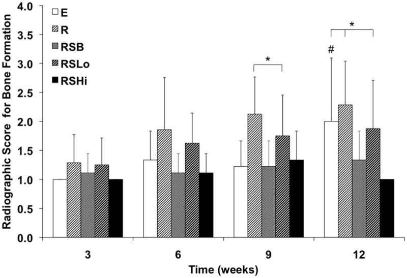
Radiographic scores for bone formation within the defect at 3, 6, 9, and 12 weeks as analyzed by the scoring system in Figure S2. Data are reported as means with standard deviations (n = 6–9). * indicates significant differences with other groups at the same timepoint (p < 0.05). # denotes that group E at week 12 is significantly different from weeks 3, 6, and 9 (p < 0.05).
3.3 Micro-CT Analysis
The amount of bone formed within the defect was evaluated both qualitatively and quantitatively at 12 weeks with micro-CT. Complete bone union was not observed in any sample as evaluated by observing three-dimensional images of the femurs as shown in Figure 4. Bone formed along the outside edges of the defect area. The majority of samples showed that the bone formation occurred along the polyethylene plate, which can be seen in the representative images. The scores given to all the groups for bridging within the defect were not significantly different at 12 weeks as shown in Figure 5.
Figure 4.

Representative micro-CT images for each group at 12 weeks. The shaded area represents the defect space with a height of 5 mm with the polyethylene plate (not-visible) being located behind the bone images. The arrow indicates the location of a removed K-wire. Bone formation occurred along the periphery of the defect area for the groups that contained a PPF rod and/or sleeve.
Figure 5.

Micro-CT scores for bone formation within the defect at 12 weeks. Data are reported as means with standard deviations (n = 8–9).
Figure 6 shows the percentage of bone volume for intact femurs (C) and all experimental groups. The percentage of bone volume for the intact femurs was significantly higher by approximately 2-fold compared to the experimental groups incorporating a defect with or without a scaffold implant (p < 0.05). Additionally, it appears the addition of rhBMP-2 produced increased bone formation although only significantly in the RSHi group which had more bone formation at 12 weeks compared to the E and RSB groups (p < 0.05).
Figure 6.
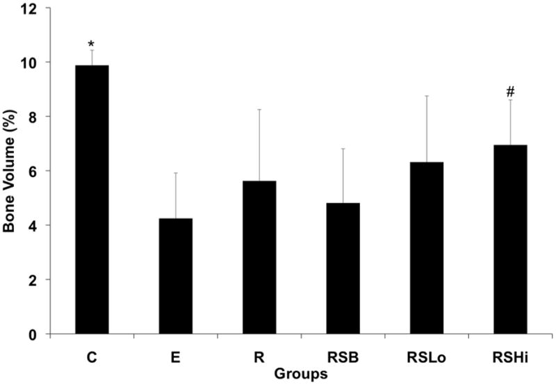
Percentage of bone volume formed at 12 weeks within the 5 mm femoral defect calculated by micro-CT for all groups. Data are reported as the means with standard deviations (n = 8–9). * indicates statistical differences compared to all the groups (p < 0.05) and # indicates significant differences to groups E and RSB (p < 0.05).
3.4 Histological Analysis
At the 12 week time point, a fibrous capsule or immature/mature bone was most commonly found surrounding the PPF rod and/or PPF porous sleeve for each group. However, no bone union was observed. When there was a presence of immature/mature bone around the scaffolds, it always surrounded the outer periphery of the PPF rod and/or PPF porous sleeve for each group. Immature cartilage was also observed in the samples, which was often near the presence of osteoids containing osteoblasts and osteoclasts. Pores within the sleeve were mainly filled with fibrous tissue. The RSLo and RSHi groups had some samples that contained bone within the outer pores of the porous sleeve versus the RSB group, which contained a layer of bone that did not penetrate the pores as shown in Figure 7. For each group, at least one rod was broken by the end of the study at 12 weeks. Whenever this occurred, one end of the rod within the intramedullary canal was always surrounded by bone.
Figure 7.
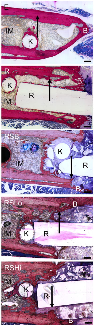
Representative histological images for each group at 12 weeks. Bone formation readily occurred at the PPF rod interface or on the periphery of the PPF porous sleeve. IM – intramedullary canal with bone marrow, R: PPF rod, B: newly formed bone, S: remaining porous scaffold, K: location of removed K-wire, arrows indicate the initial defect margin. Scale bars represent 500 μm.
The tissue response was evaluated for all the groups (n=3–4) at the bone-rod interface, bone-sleeve interface, and within the pores of the sleeve at 12 weeks as shown in Figure 8a–c. Figure 8a shows tissue response scores at the rod interface within the intramedullary canal (IM) and the defect area. The RSLo and RSHi groups showed significantly lower scores compared to the R and RSB group within the intramedullary canal (p < 0.05). However, within the defect area, no differences were observed.
Figure 8.
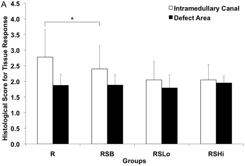
Histological scores for the hard tissue response at week 12 (A) at the rod interface within the intramedullary canal (□) and within the 5 mm defect area (■), (B) at the porous PPF sleeve interface along the initial defect margin (□) and within the defect area (■) and (C) within the pores of the porous PPF sleeve; as well as (D) for the presence of cartilage formation against the solid PPF rod within the intramedullary canal (□) and within the defect area (
 ), and against the porous PPF sleeve (■). Data are reported as means with standard deviations (n=3–4). * indicates statistical differences compared to other groups (p < 0.05).
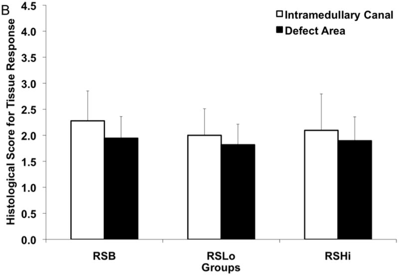
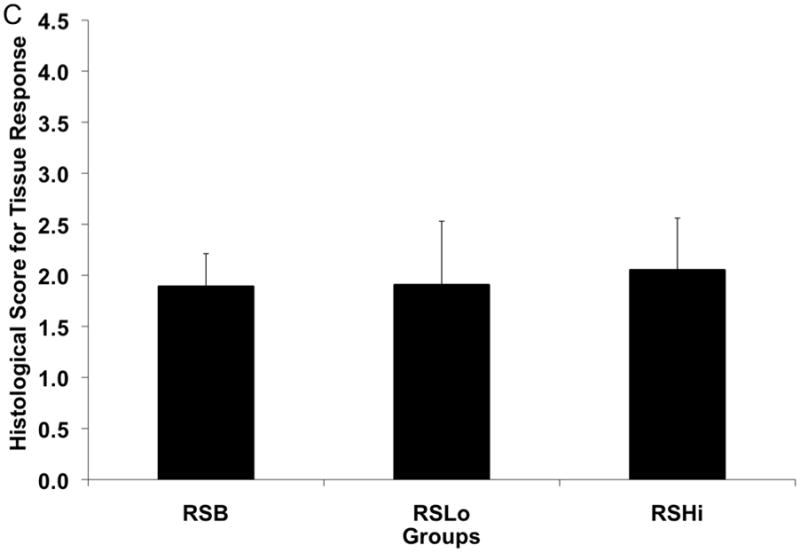
The scoring of the hard tissue response at the porous sleeve interface can be seen in Figure 8b. Two different locations were evaluated at the porous sleeve interface: adjacent to the original defect and within the central defect area. No significant differences were observed for either of the interface areas at week 12. Tissue response scores within the pores of the PPF porous sleeve were given for the RSB, RSLo, and RSHi groups as shown in Figure 8c. The results showed that no significant differences were observed between all the groups.
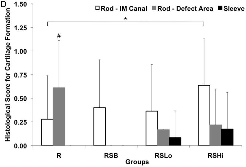
The presence of cartilage was also evaluated at the rod interface, within the intramedullary canal and defect area, as well as within the pores of the porous sleeve as shown in Figure 8d with a representative image shown in Figure 9. The rod interface created significantly more immature cartilage tissue compared to the RSHi group within the intramedullary canal (p < 0.05). The R group also showed more cartilage formation than the rest of the other groups along the rod interface within the defect area (p < 0.05). Cartilage was not found for the RSB group at the rod-defect area. The pores within the sleeve were also evaluated for cartilage tissue formation and no significant differences were found.
Figure 9.
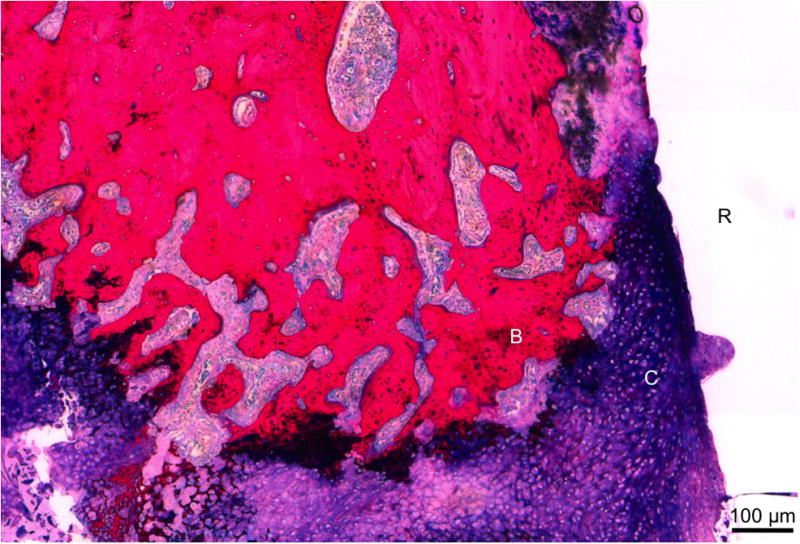
Representative histological section of group R at 12 weeks. Immature cartilage formation (C), noted by the dark purple matrix with blue cells, was found along the PPF rod surface (R). Newly formed bone (B) was found along the cartilage. Scale bar represents 100 μm.
3.5 Biomechanical Analysis
Torsional mechanical testing was performed to assess the functional recovery of sample femurs. All experimental groups exhibited significantly greater maximum torque (N-mm) and torsional stiffness (N-mm/°) when compared to empty defects (p < 0.01) as shown in Figure 10. Additionally, the femurs of animals receiving low dose rhBMP-2 exhibited significantly greater maximum torque than those with a rod alone (p < 0.05). For torsional stiffness, both groups receiving rhBMP-2 performed significantly better than the group with only the rod (p < 0.05). Contralateral control femurs from each rat were also tested and exhibited significantly higher torque and stiffness for each sample (p < 0.05).
Figure 10.
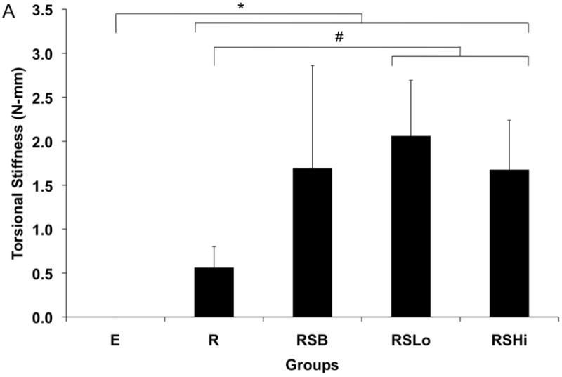
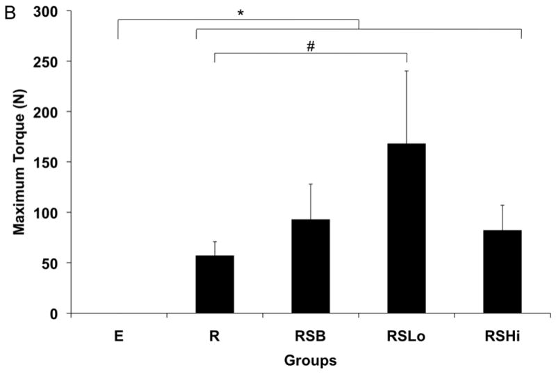
Torsional stiffness (A) and maximum torque (B) for harvested specimens from each group at 12 weeks. Data are reported as means with standard deviation (n=6). * indicates significant differences between all experimental groups and empty defects (p < 0.01). # indicates significant differences between groups marked (p < 0.05).
4. Discussion
To address the mechanical as well as regenerative requirements of segmental defects, structural components of tissue engineering strategies must be considered. Clinically used intramedullary rods or internally fixed plates provide mechanical support, but require lifetime placement or subsequent surgical removal. Considering the scaffold requirements for stabilization and tissue engineering two conflicting principles must be addressed, decreased porosity for strength and increased porosity for tissue ingrowth and remodeling. A composite scaffold provides potential for these principles to be addressed.
In this study, a composite scaffold design was hypothesized to increase mechanical stabilization through incorporation of a solid PPF intramedullary rod and bone tissue integration through a porous PPF sleeve in a critical size rat femoral defect. Additionally, increased bone regeneration was hypothesized in groups with increased levels of rhBMP-2. The study results indicate that mechanical properties were enhanced by the presence of the scaffolds as shown in Figure 10 and the quantity of bone regeneration increased with rhBMP-2 delivery.
The scaffold clearly impacted the results through all analyses, including bone regeneration, mechanical stability and tissue response. Mechanical stability was increased in the presence of a scaffold in all groups and was further increased with a low dose of rhBMP-2. The relationship between bone regeneration and mechanical strength has been previously reported in both ceramic and polymeric materials in calvaria [49–51] and long bones [5, 47]. Consistent with the studies in long bones, increased bone formation increased the mechanical stability of implants, even when bridging did not occur.
Additionally, the radiographic scores showed that group R regenerated more bone than the RSB group at weeks 9 and 12. In the group with only the rod, there was no direct apposition of a porous scaffold to the cut cortical bone surface, which prevented direct growth of bone from the cut plane of bone. In all groups with the porous sleeve, the scaffold was in immediate apposition to the cut surface of bone, filling the space of potential bone growth. As indicated in Figure 7, there was not significant PPF degradation over the 12 weeks, such that the potential space for bone growth was not created by degradation and bone regeneration was limited to the pores of the scaffold and the outer surface as seen in the radiograph (Figure 2) and micro-CT images (Figure 4). This limited the majority of bone growth in groups with the porous sleeve to the surface, which has been previously described.[18, 21, 52] In a study by Woodard et al., growth into the scaffold was dependent upon the presence of micropores (2–8 μm) and limited to surface growth when only larger pores were present as is in this study.[18] Another study by Aronin et al. similarly found that smaller pore sizes (100 μm) had increased tissue infiltration compared to larger pore sizes (500 μm) in rat critical size cranial defects.[53] In addition to pore size, pore and scaffold architecture have also been shown to play a critical role in tissue response. [17, 54–56] For example, Kim et al. showed that scaffolds fabricated by stereolithography with a highly permeable and porous architecture induced upregulation of osteogenic signal expression with rat bone marrow stromal cells in vitro when compared to random porous architecture as in this study.[56] Another interesting study found that scaffold architectures that mimic the structure of native bone have exhibited up to a 500% increase in bone volume when compared to defined architectures.[57]
Decreased bone formation as a result of the porous sleeve can also be attributed to isolation of cell sources. The osteoprogenitor cells responsible for regenerating the bone in these acellular scaffolds would likely be cells from the periosteum or the bone marrow. As the porous sleeve separates these two populations with an open but tortuous route, the impact of both cell types on bone regeneration could be diminished. Additionally, the presence of a solid rod within the intramedullary canal may have also inhibited the migration of osteoprogenitor cells originating from the bone marrow. Therefore, as in other previous studies that incorporate PLGA microspheres into PPF intramedullary rods [21, 30], it may be advantageous to bone formation to incorporate a porogen into the rod in order to facilitate increased migration of progenitor cells out of the intramedullary canal and into the defect although diminishing the mechanical support. Alternatively, surface microgrooves could be incorporated to allow for migration of cells through the channels which has been previously investigated.[58] Scaffold design also had a significant impact on the cartilage tissue response. Within the defect area, group R showed significantly more cartilage formation than any other group. Cartilage formation in bone defects has been previously reported by Sarkar et al.[59] This immature cartilage formation could lead to bone regeneration through hypertrophy of the chondrocytes and ossification. Additionally, other factors could contribute to the chondrogenesis present in the defect, such as low oxygen tension due to removal of vasculature present in the defect previously, or the instability of the rod within the intramedullary canal leading to chondrocyte inducing micromotion.
Delivery of rhBMP-2 also affected the bone regeneration, mechanical stability and tissue response. While radiography indicated the low dose rhBMP-2 group to have the greatest bone regeneration at 12 weeks, micro-CT indicated the most bone formation in the high dose rhBMP-2 group. As micro-CT is a quantifiable technique opposed to a viewer scored system, it is more reliable at accurately measuring bone formation although radiography may indicate density of bone growth in greater detail. This hypothesis is supported by the mechanical data, which showed the group RSLo had increased mechanical stability relative to the R group. Integration between the regenerated bone and the scaffold was not significant as shown through the histological scores for the tissue present within the pores of the scaffold. Therefore, the transmittance of load between the regenerated bone and the scaffold imparted in the group RSLo is attributed to the strength of bone surrounding the scaffold. Previous studies have shown there can be a lack of correlation between the bone regeneration in a scaffold and the resultant mechanical properties at the interface as was seen with groups RSLo and RSHi.[49, 50]
The release rate of adsorbed rhBMP-2 from PLGA microparticles in this study may also have affected bone formation. A previous in vitro study by Patel et al. found that rhBMP-2 adsorbed onto PLGA microparticles exhibited a burst release of approximately 30% followed by sustained release for over 28 days.[33] However, a separate study found that when incorporated into a scaffold such as calcium phosphate and implanted subcutaneously in rats, rhBMP-2 adsorbed on PLGA microparticles exhibited minimal burst and a more linear release over 28 days when monitored in vivo.[38] In the current study, entrapment of the PLGA microparticles within the porous PPF scaffold may have extended the release of rhBMP-2 and inhibited a burst release to some extent. Although not significant, this may be evidenced by the increase in bone formation observed between weeks 3 and 6 for the group containing low dose rhBMP-2 when compared to the porous scaffold group containing no rhBMP-2.
The tissue response showed decreased scores (more fibrous tissue and/or inflammatory cells present) adjacent to the rod in the intramedullary canal when there was rhBMP-2 present. Recently, with the increased clinical use of rhBMP-2, case reports and studies have shown inflammatory processes likely caused by the release of rhBMP-2.[60, 61] While the mechanism has not been directly identified, the phenomenon has caused reconsideration of use of rhBMP-2 near swelling sensitive tissues such as airways. This same process could explain the increased inflammation present in the groups with rhBMP-2.
Finally, there was increased cartilage formation against the rod in the intramedullary canal when higher doses of rhBMP-2 were delivered compared to the rod alone. Previous studies have shown that that mesenchymal stem cells can be induced down a chondrogenic lineage when in low oxygen tension environments and in the presence of rhBMP-2.[62] This result also suggests higher concentration of rhBMP-2 in the intramedullary canal in the RSHi group versus the RSLo group. This observation is consistent with the decreased mechanical strength in the RSHi group versus RSLo group. As the cartilage formed could be well vascularized if given enough time this would be expected to undergo hypertrophy and ossification creating bone tissue, although that was not seen in the 12 weeks of this study.
Several conclusions can be drawn from the model system described above regarding bone regeneration with rhBMP-2 with porous scaffolds in the defect, but to further understand the relationship between these two components more groups would be necessary. Primarily, a group with the porous sleeve without the rod, while contrary to the objective of increased stability, could allow for more investigation into the role of bone marrow stromal cells in the regenerative process. Additionally, including groups which deliver rhBMP-2 without the porous scaffold, could show the degree of effect of the porous scaffold has on bone regeneration. Finally, a larger animal model would be necessary to further investigate the role of mechanical stability as this model describes a load-bearing bone, off-loaded by internal fixation. While the majority of the defect load is supported by the polyethylene plate, the results indicate some degree of load transfer to the scaffold, indicated by the breaking of the rod in scaffolds where the rod was surrounded by new bone within the intramedullary canal. Nevertheless, this study clearly indicates the increased stabilization effect of composite scaffolds utilizing both porous and solid structures as shown by the increase in mechanical strength of group R over group E and group RSLo over group R. Additionally, rhBMP-2 increased bone formation as hypothesized.
5. Conclusion
The presented study analyzed the effects of composite scaffold construction, which aimed to address the bone regeneration and stabilization concerns of non-union fractures. While in no experimental groups was the segmental femoral defect in the rat bridged, many conclusions can be drawn concerning scaffold design from this model system. These conclusions address issues regarding the source of stem cell populations in an acellular construct, factors associated with stabilization of non-unions, and environmental factors present in a defect driving cell differentiation. Results showed increased bone formation in groups without the porous sleeve, suggesting the role of the sleeve as a physical barrier to both bone growth and to the migration of regenerative cells present in the bone marrow and periosteal regions. Conversely, while the scaffold was shown to hinder bone bridging, it did impart significant mechanical strength to the defect, a critical objective to non-union therapy.
Supplementary Material
Schematic diagram of method used to place 8.5 mm rod into intramedullary canal with 5 mm defect. The defect was cut with the plat in place (A), then the two K-wires adjacent to the defect were removed (B). The bone segments were rotated towards the surgeon (C) and the PPF rod placed in the proximal bone segement’s intramedullary canal (D). The bone segments and rod were rotated back into alignment, while simultaneously placing the rod into the distal bone segment (E). Finally, the K-wires were reset (F).
Schematic representation of the scoring system used for evaluation of radiographic and micro-CT images.[46]
Acknowledgments
Research towards the development of biomaterials for bone tissue engineering was supported by DARPA (W911NF-09-1-0044) and NIH (R01-DE017441). P.P.S. acknowledges the support of the Robert and Janice McNair Foundation. V.V.M acknowledges support from the Academy of Finland (124054). We additionally acknowledge Drs. Michael J. Yaszemski, Lichun Lu, and Diederik H.R. Kempen for their assistance concerning the surgical procedure.
Footnotes
Publisher's Disclaimer: This is a PDF file of an unedited manuscript that has been accepted for publication. As a service to our customers we are providing this early version of the manuscript. The manuscript will undergo copyediting, typesetting, and review of the resulting proof before it is published in its final citable form. Please note that during the production process errors may be discovered which could affect the content, and all legal disclaimers that apply to the journal pertain.
References
- 1.Borrelli J, Prickett WD, Ricci WM. Treatment of nonunions and osseous defects with bone graft and calcium sulfate. Clin Orthop Relat Res. 2003;411:245–54. doi: 10.1097/01.blo.0000069893.31220.6f. [DOI] [PubMed] [Google Scholar]
- 2.Sawin PD, Traynelis VC, Menezes AH. A comparative analysis of fusion rates and donor-site morbidity for autogeneic rib and iliac crest bone grafts in posterior cervical fusions. J Neurosurg. 1998;88:255–65. doi: 10.3171/jns.1998.88.2.0255. [DOI] [PubMed] [Google Scholar]
- 3.Sitharaman B, Shi X, Tran LA, Spicer PP, Rusakova I, Wilson LJ, Mikos AG. Injectable in situ cross-linkable nanocomposites of biodegradable polymers and carbon nanostructures for bone tissue engineering. J Biomater Sci Polym Ed. 2007;18:655–71. doi: 10.1163/156856207781034133. [DOI] [PubMed] [Google Scholar]
- 4.Shi X, Hudson JL, Spicer PP, Tour JM, Krishnamoorti R, Mikos AG. Rheological behaviour and mechanical characterization of injectable poly (propylene fumarate)/single-walled carbon nanotube composites for bone tissue engineering. Nanotechnology. 2005;16:S531–8. doi: 10.1088/0957-4484/16/7/030. [DOI] [PubMed] [Google Scholar]
- 5.Chu TG, Warden SJ, Turner CH, Stewart RL. Segmental bone regeneration using a load-bearing biodegradable carrier of bone morphogenetic protein-2. Biomaterials. 2007;28:459–67. doi: 10.1016/j.biomaterials.2006.09.004. [DOI] [PMC free article] [PubMed] [Google Scholar]
- 6.Balçik C, et al. Early weight bearing of porous HA/TCP (60/40) ceramics in vivo: A longitudinal study in a segmental bone defect model of rabbit. Acta Biomater. 2007;3:985–96. doi: 10.1016/j.actbio.2007.04.004. [DOI] [PubMed] [Google Scholar]
- 7.Rybicki EF, Simonen FA, Weis EB. On the mathematical analysis of stress in the human femur. J Biomech. 1972;5:203–15. doi: 10.1016/0021-9290(72)90056-5. [DOI] [PubMed] [Google Scholar]
- 8.Shi X, et al. Fabrication of porous ultra-short single-walled carbon nanotube nanocomposite scaffolds for bone tissue engineering. Biomaterials. 2007;28:4078–90. doi: 10.1016/j.biomaterials.2007.05.033. [DOI] [PMC free article] [PubMed] [Google Scholar]
- 9.Bruder SP, Kraus KH, Goldberg VM, Kadiyala S. The Effect of Implants Loaded with Autologous Mesenchymal Stem Cells on the Healing of Canine Segmental Bone Defects. J Bone Joint Surg Am. 1998;80:985–96. doi: 10.2106/00004623-199807000-00007. [DOI] [PubMed] [Google Scholar]
- 10.Guelcher SA. Biodegradable polyurethanes: synthesis and applications in regenerative medicine. Tissue Eng Pt B Rev. 2008;14:3–17. doi: 10.1089/teb.2007.0133. [DOI] [PubMed] [Google Scholar]
- 11.Oest ME, Dupont KM, Kong HJ, Mooney DJ, Guldberg RE. Quantitative assessment of scaffold and growth factor-mediated repair of critically sized bone defects. J Orthop Res. 2007;25:941–50. doi: 10.1002/jor.20372. [DOI] [PubMed] [Google Scholar]
- 12.Fisher JP, et al. Effect of biomaterial properties on bone healing in a rabbit tooth extraction socket model. J Biomed Mater Res A. 2004;68A:428–38. doi: 10.1002/jbm.a.20073. [DOI] [PubMed] [Google Scholar]
- 13.Fisher JP, Vehof JW, Dean D, van der Waerden JP, Holland TA, Mikos AG, Jansen JA. Soft and hard tissue response to photocrosslinked poly(propylene fumarate) scaffolds in a rabbit model. J Biomed Mater Res Part A. 2002;59A:547–56. doi: 10.1002/jbm.1268. [DOI] [PubMed] [Google Scholar]
- 14.Mistry AS, Pham QP, Schouten C, Yeh T, Christenson EM, Mikos AG, Jansen JA. In vivo bone biocompatibility and degradation of porous fumarate-based polymer/alumoxane nanocomposites for bone tissue engineering. J Biomed Mater Res A. 2010;92A:451–62. doi: 10.1002/jbm.a.32371. [DOI] [PMC free article] [PubMed] [Google Scholar]
- 15.Yaszemski MJ, Payne RG, Hayes WC, Langer R, Aufdemorte TB, Mikos AG. The ingrowth of new bone tissue and initial mechanical properties of a degrading polymeric composite scaffold. Tissue Eng. 1995;1:41–52. doi: 10.1089/ten.1995.1.41. [DOI] [PubMed] [Google Scholar]
- 16.Peter SJ, Lu L, Kim DJ, Mikos AG. Marrow stromal osteoblast function on a poly(propylene fumarate)/beta-tricalcium phosphate biodegradable orthopaedic composite. Biomaterials. 2000;21:1207–13. doi: 10.1016/s0142-9612(99)00254-9. [DOI] [PubMed] [Google Scholar]
- 17.Kim K, Yeatts A, Dean D, Fisher JP. Stereolithographic Bone Scaffold Design Parameters: Osteogenic Differentiation and Signal Expression. Tissue Eng Pt B Rev. 2010;16:523–39. doi: 10.1089/ten.teb.2010.0171. [DOI] [PMC free article] [PubMed] [Google Scholar]
- 18.Woodard JR, et al. The mechanical properties and osteoconductivity of hydroxyapatite bone scaffolds with multi-scale porosity. Biomaterials. 2007;28:45–54. doi: 10.1016/j.biomaterials.2006.08.021. [DOI] [PubMed] [Google Scholar]
- 19.Brown JL, Peach MS, Nair LS, Kumbar SG, Laurencin CT. Composite scaffolds: Bridging nanofiber and microsphere architectures to improve bioactivity of mechanically competent constructs. J Biomed Mater Res A. 2010;95A:1150–8. doi: 10.1002/jbm.a.32934. [DOI] [PubMed] [Google Scholar]
- 20.Nguyen C, Young S, Kretlow JD, Mikos AG, Wong ME. Surface Characteristics of Biomaterials Used for Space Maintenance in a Mandibular Defect: A Pilot Animal Study. J Oral Maxillofac Surg. 2011;69:11–8. doi: 10.1016/j.joms.2010.02.026. [DOI] [PubMed] [Google Scholar]
- 21.Kempen DHR, et al. Effect of local sequential VEGF and BMP-2 delivery on ectopic and orthotopic bone regeneration. Biomaterials. 2009;30:2816–25. doi: 10.1016/j.biomaterials.2009.01.031. [DOI] [PubMed] [Google Scholar]
- 22.Ito Y. Tissue engineering by immobilized growth factors. Materials Science and Engineering: C. 1998;6:267–74. [Google Scholar]
- 23.Ahrendt G, Chickering DE, Ranieri JP. Angiogenic Growth Factors: A Review for Tissue Engineering. Tissue Eng. 1998;4:117–30. [Google Scholar]
- 24.Boden S. Bioactive factors for bone tissue engineering. Clin Orthop Relat R. 1999:S84–94. doi: 10.1097/00003086-199910001-00009. [DOI] [PubMed] [Google Scholar]
- 25.Babensee JE, McIntire LV, Mikos AG. Growth Factor Delivery for Tissue Engineering. Pharm Res. 2000;17:497–504. doi: 10.1023/a:1007502828372. [DOI] [PubMed] [Google Scholar]
- 26.Tabata Y. Tissue regeneration based on growth factor release. Tissue Engineering. 2003;9:S5–15. doi: 10.1089/10763270360696941. [DOI] [PubMed] [Google Scholar]
- 27.Rose FRAJ, Hou Q, Oreffo ROC. Delivery systems for bone growth factors—the new players in skeletal regeneration. J Pharm Pharmacol. 2004;56:415–27. doi: 10.1211/0022357023312. [DOI] [PubMed] [Google Scholar]
- 28.Chen D, Zhao M, Mundy GR. Bone Morphogenetic Proteins. Growth Factors. 2004;22:233–41. doi: 10.1080/08977190412331279890. [DOI] [PubMed] [Google Scholar]
- 29.Jeon O, et al. Long-term delivery enhances in vivo osteogenic efficacy of bone morphogenetic protein-2 compared to short-term delivery. Biochem Biophys Res Commun. 2008;369:774–80. doi: 10.1016/j.bbrc.2008.02.099. [DOI] [PubMed] [Google Scholar]
- 30.Kempen DHR, et al. Retention of in vitro and in vivo BMP-2 bioactivities in sustained delivery vehicles for bone tissue engineering. Biomaterials. 2008;29:3245–52. doi: 10.1016/j.biomaterials.2008.04.031. [DOI] [PMC free article] [PubMed] [Google Scholar]
- 31.Kempen DHR, et al. Non-invasive monitoring of BMP-2 retention and bone formation in composites for bone tissue engineering using SPECT/CT and scintillation probes. J Controlled Release. 2009;134:169–76. doi: 10.1016/j.jconrel.2008.11.023. [DOI] [PMC free article] [PubMed] [Google Scholar]
- 32.Young S, et al. Dose effect of dual delivery of vascular endothelial growth factor and bone morphogenetic protein-2 on bone regeneration in a rat critical-size defect model. Tissue Eng Pt A. 2009;15:2347–62. doi: 10.1089/ten.tea.2008.0510. [DOI] [PMC free article] [PubMed] [Google Scholar]
- 33.Patel ZS, Yamamoto M, Ueda H, Tabata Y, Mikos AG. Biodegradable gelatin microparticles as delivery systems for the controlled release of bone morphogenetic protein-2. Acta Biomaterialia. 2008;4:1126–38. doi: 10.1016/j.actbio.2008.04.002. [DOI] [PMC free article] [PubMed] [Google Scholar]
- 34.Patel ZS, Young S, Tabata Y, Jansen JA, Wong MEK, Mikos AG. Dual delivery of an angiogenic and an osteogenic growth factor for bone regeneration in a critical size defect model. Bone. 2008;43:931–40. doi: 10.1016/j.bone.2008.06.019. [DOI] [PMC free article] [PubMed] [Google Scholar]
- 35.Kim S, Gwak S, Kim B. Orthotopic bone formation by implantation of apatite-coated poly(lactide-co-glycolide)/hydroxyapatite composite particulates and bone morphogenetic protein-2. J Biomed Mater Res A. 2008;87:245–53. doi: 10.1002/jbm.a.31782. [DOI] [PubMed] [Google Scholar]
- 36.Lane JM, et al. Bone marrow and recombinant human bone morphogenetic protein-2 in osseous repair. Clin Orthop Relat Res. 1999:216–27. doi: 10.1097/00003086-199904000-00028. [DOI] [PubMed] [Google Scholar]
- 37.Ruhé PQ, Hedberg EL, Padron NT, Spauwen PHM, Jansen JA, Mikos AG. rhBMP-2 Release from Injectable Poly(DL-Lactic-co-glycolic Acid)/Calcium-Phosphate Cement Composites. J Bone Joint Surg Am. 2003;85:75–81. doi: 10.2106/00004623-200300003-00013. [DOI] [PubMed] [Google Scholar]
- 38.Ruhe PQ, Boerman OC, Russel FGM, Spauwen PHM, Mikos AG, Jansen JA. Controlled release of rhBMP-2 loaded poly(DL-lactic-co-glycolic acid)/calcium phosphate cement composites in vivo. J Control Release. 2005;106:162–71. doi: 10.1016/j.jconrel.2005.04.018. [DOI] [PubMed] [Google Scholar]
- 39.Shung AK, Timmer MD, Jo S, Engel PS, Mikos AG. Kinetics of poly (propylene fumarate) synthesis by step polymerization of diethyl fumarate and propylene glycol using zinc chloride as a catalyst. J Biomater Sci Polym Ed. 2002;13:95–108. doi: 10.1163/156856202753525963. [DOI] [PubMed] [Google Scholar]
- 40.Kasper FK, Tanahashi K, Fisher JP, Mikos AG. Synthesis of poly (propylene fumarate) Nat Protoc. 2009;4:518–25. doi: 10.1038/nprot.2009.24. [DOI] [PMC free article] [PubMed] [Google Scholar]
- 41.Yasko AW, Lane JM, Fellinger EJ, Rosen V, Wozney JM, Wang EA. The healing of segmental bone defects, induced by recombinant human bone morphogenetic protein (rhBMP-2). A radiographic, histological, and biomechanical study in rats. J Bone Joint Surg Am. 1992;74:659–70. [PubMed] [Google Scholar]
- 42.Drosse I, et al. Validation of a femoral critical size defect model for orthotopic evaluation of bone healing: a biomechanical, veterinary and trauma surgical perspective. Tissue Eng Pt C-Meth. 2008;14:79–88. doi: 10.1089/tec.2007.0234. [DOI] [PubMed] [Google Scholar]
- 43.Einhorn TA, Lane JM, Burstein AH, Kopman CR, Vigorita VJ. The healing of segmental bone defects induced by demineralized bone matrix. A radiographic and biomechanical study. The Journal of bone and joint surgery American volume. 1984;66:274–9. [PubMed] [Google Scholar]
- 44.Jansen JA. Histological Analysis of Bone-Implant Interface. In: An YH, Martin KL, editors. Handbook of histology methods for bone and cartilage. Totowa, New Jersey: Humana Press; 2003. pp. 353–60. [Google Scholar]
- 45.Hedberg EL, et al. Methods: A Comparative Analysis of Radiography, Microcomputed Tomography, and Histology for Bone Tissue Engineering. Tissue Eng. 2005;11:1356–67. doi: 10.1089/ten.2005.11.1356. [DOI] [PubMed] [Google Scholar]
- 46.Feldkamp LA, Davis LC, Kress JW. Practical cone-beam algorithm. J Opt Soc Am. 1984;1:612–9. [Google Scholar]
- 47.Rai B, Oest ME, Dupont KM, Ho KH, Teoh SH, Guldberg RE. Combination of platelet-rich plasma with polycaprolactone-tricalcium phosphate scaffolds for segmental bone defect repair. J Biomed Mater Res Pt A. 2007;81A:888–99. doi: 10.1002/jbm.a.31142. [DOI] [PubMed] [Google Scholar]
- 48.Kokubu T, Hak DJ, Hazelwood SJ, Reddi AH. Development of an atrophic nonunion model and comparison to a closed healing fracture in rat femur. J Orthop Res. 2003;21:503–10. doi: 10.1016/S0736-0266(02)00209-7. [DOI] [PubMed] [Google Scholar]
- 49.Kretlow JD, Spicer PP, Jansen J, Vacanti CA, Kasper FK, Mikos AG. Uncultured marrow mononuclear cells delivered within fibrin glue hydrogels to porous scaffolds enhance bone regeneration within critical size rat cranial defects. Tissue Eng Pt A. 2010;16:3555–68. doi: 10.1089/ten.tea.2010.0471. [DOI] [PMC free article] [PubMed] [Google Scholar]
- 50.Hing KA, Best SM, Tanner KE, Bonfield W, Revell PA. Mediation of bone ingrowth in porous hydroxyapatite bone graft substitutes. J Biomed Mater Res A. 2004;68A:187–200. doi: 10.1002/jbm.a.10050. [DOI] [PubMed] [Google Scholar]
- 51.Schantz JT, et al. Repair of calvarial defects with customised tissue-engineered bone grafts - II. Evaluation of cellular efficiency and efficacy in vivo. Tissue Eng. 2003;9:S127–S39. doi: 10.1089/10763270360697030. [DOI] [PubMed] [Google Scholar]
- 52.Hedberg EL, Kroese-Deutman HC, Shih CK, Crowther RS, Carney DH, Mikos AG, Jansen JA. Effect of varied release kinetics of the osteogenic thrombin peptide TP508 from biodegradable, polymeric scaffolds on bone formation in vivo. J Biomed Mater Res. 2005;72:343–53. doi: 10.1002/jbm.a.30265. [DOI] [PubMed] [Google Scholar]
- 53.Aronin CE, Sadik KW, Lay AL, Rion DB, Tholpady SS, Ogle RC, Botchwey EA. Comparative effects of scaffold pore size, pore volume, and total void volume on cranial bone healing patterns using microsphere-based scaffolds. Journal of Biomedical Materials Research Part A. 2009;89A:632–41. doi: 10.1002/jbm.a.32015. [DOI] [PMC free article] [PubMed] [Google Scholar]
- 54.Lee JW, Lan PX, Kim B, Lim G, Cho D. Fabrication and characteristic analysis of a poly (propylene fumarate) scaffold using micro-stereolithography technology. J Biomed Mater Res B. 2008;87B:1–9. doi: 10.1002/jbm.b.31057. [DOI] [PubMed] [Google Scholar]
- 55.Melchels FPW, Feijen J, Grijpma DW. A poly (d, l-lactide) resin for the preparation of tissue engineering scaffolds by stereolithography. Biomaterials. 2009;30:3801–9. doi: 10.1016/j.biomaterials.2009.03.055. [DOI] [PubMed] [Google Scholar]
- 56.Kim K, Dean D, Wallace J, Breithaupt R, Mikos AG, Fisher JP. The Influence of Stereolithographic Scaffold Architecture and Composition on Osteogenic Signal Expression with Rat Bone Marrow Stromal Cells. Biomaterials. 2011 doi: 10.1016/j.biomaterials.2011.01.016. in press. [DOI] [PMC free article] [PubMed] [Google Scholar]
- 57.Geffre CP, Margolis DS, Ruth JT, DeYoung DW, Tellis BC, Szivek JA. A novel biomimetic polymer scaffold design enhances bone ingrowth. J Biomed Mater Res A. 2009;91A:795–805. doi: 10.1002/jbm.a.32251. [DOI] [PMC free article] [PubMed] [Google Scholar]
- 58.Ricci JL, Grew JC, Alexander H. Connective-tissue responses to defined biomaterial surfaces. I. Growth of rat fibroblast and bone marrow cell colonies on microgrooved substrates. Journal of Biomedical Materials Research Part B: Applied Biomaterials. 2008;85A:313–25. doi: 10.1002/jbm.a.31379. [DOI] [PubMed] [Google Scholar]
- 59.Sarkar MR, et al. Bone formation in a long bone defect model using a platelet-rich plasma-loaded collagen scaffold. Biomaterials. 2006;27:1817–23. doi: 10.1016/j.biomaterials.2005.10.039. [DOI] [PubMed] [Google Scholar]
- 60.Shields LBE, Raque GH, Glassman SD, Campbell M, Vitaz T, Harpring J, Shields CB. Adverse effects associated with high-dose recombinant human bone morphogenetic protein-2 use in anterior cervical spine fusion. Spine. 2006;31:542–7. doi: 10.1097/01.brs.0000201424.27509.72. [DOI] [PubMed] [Google Scholar]
- 61.Perri B, Cooper M, Lauryssen C, Anand N. Adverse swelling associated with use of rh-BMP-2 in anterior cervical discectomy and fusion: a case study. Spine J. 2007;7:235–9. doi: 10.1016/j.spinee.2006.04.010. [DOI] [PubMed] [Google Scholar]
- 62.Heng BC, Cao T, Lee EH. Directing stem cell differentiation into the chondrogenic lineage in vitro. Stem Cells. 2004;22:1152–67. doi: 10.1634/stemcells.2004-0062. [DOI] [PubMed] [Google Scholar]
Associated Data
This section collects any data citations, data availability statements, or supplementary materials included in this article.
Supplementary Materials
Schematic diagram of method used to place 8.5 mm rod into intramedullary canal with 5 mm defect. The defect was cut with the plat in place (A), then the two K-wires adjacent to the defect were removed (B). The bone segments were rotated towards the surgeon (C) and the PPF rod placed in the proximal bone segement’s intramedullary canal (D). The bone segments and rod were rotated back into alignment, while simultaneously placing the rod into the distal bone segment (E). Finally, the K-wires were reset (F).
Schematic representation of the scoring system used for evaluation of radiographic and micro-CT images.[46]