Abstract
The quest for synthetic materials to repair load-bearing bone lost because of trauma, cancer, or congenital bone defects requires development of porous and high-performance scaffolds with exceptional mechanical strength. However, the low mechanical strength of porous bioactive ceramic and glass scaffolds, compared with that of human cortical bone, has limited their use for these applications. In the present work, bioactive 6P53B glass scaffolds with superior mechanical strength were fabricated using a direct ink writing technique. The rheological properties of Pluronic® F-127 (referred to hereafter simply as F-127) hydrogel-based inkswere optimized for the printing of features as fine as 30 μm and of the three-dimensional scaffolds. The mechanical strength and in vitro degradation of the scaffolds were assessed in a simulated body fluid (SBF). The sintered glass scaffolds show a compressive strength (136 ± 22 MPa) comparable to that of human cortical bone (100-150 MPa), while the porosity (60%) is in the range of that of trabecular bone (50-90%).The strength is ~100 times that of polymer scaffolds and 4–5 times that of ceramic and glass scaffolds with comparable porosities. Despite the strength decrease resulting from weight loss during immersion in an SBF, the value (77 MPa) is still far above that of trabecular bone after three weeks. The ability to create both porous and strong structures opens a new avenue for fabricating scaffolds for load-bearing bone defect repair and regeneration.
Keywords: porous and strong scaffolds, bone tissue engineering, direct ink writing
1. Introduction
Bioactive glass and ceramics have shown excellent potential in repair and regeneration of bone defects because of their widely recognized ability to support the growth of bone cells, strong bonding to hard and soft tissues, and ability to adjust the degradation rate while newly formed bone and tissue are being remodeled [1-4]. The release of ions from bioactive glass is also reported to activate the expression of osteogenic genes and to stimulate angiogenesis[5-7]. Recently, there has been increasing interest in using bioactive glass as scaffold material for bone repair [1, 8-13] because of the ease at which their chemical composition, and thus their rate of degradation, can be controlled. The structure and chemistry of glasses can be tailored over a wide range by changing their composition or their thermal or environmental processing history. Therefore, it is possible to design glass scaffolds with desirable degradation rates to match that of bone ingrowth and remodeling. A variety of techniques, including polymer foam replication [8, 9], sol-gel [10], and freeze-casting [11], has been used for the fabrication of glass scaffolds. However, the low compressive strength of these scaffolds (0.2-28 MPa for porosity of 92-40%) limits their application in the repair of load-bearing bone defects.
Direct ink writing is a layer-by-layer assembly technique that has been used to fabricate constructs with materials including polymeric [14], sol-gel [15], and ceramic inks [16-19]. The technique can be used to build scaffold structures designed by a computer. Scaffold architecture therefore can be optimized to achieve the desired mechanical response, accelerate the bone-regeneration process, and guide the formation of bone with anatomic cortical-trabecular structure [20].Achieving these goals, however, requires a process able to print a wide range of materials with custom-made compositions and increased precision. In the design of such a process, the formulation of concentrated inks with the optimal rheological properties is crucial. The ink must be extruded through a fine nozzle in filamentary form and deposited over gaps that could be as large as 1–2 mm over the prior layer — while maintaining the weight of the printed structure. Concentrated ceramic inks are formulated by dispersing ceramic particles in water and using polyethyleneimine (PEI) as a coagulant agent. The viscoelastic behavior of the ink is determined by the interaction between the ionized PEI and the ammonium polyacrylate-based dispersant absorbed on the particle surface [21-23]. However, precise control of the amount of dispersant and PEI is required, as is careful manipulation of the pH. Such control is difficult with PEI-formulated inks. For a flexible ink formulation that can print a wide range of ceramics, a hydrogel-based ink was developed by dispersing ceramic particles in a water-based solution of F-127 [16]. The ink showed good flowability and could be used to print various calciumphosphate constructs, reaching a minimum line diameter of 100 μm.
Despite recent research on the use of direct ink writing for preparation of calcium phosphate scaffolds [16, 21, 22], the technique has not been used for fabrication of bioactive glass scaffolds. We hypothesize that 3-D scaffolds with superior mechanical strength can be obtained by printing glass ink with an optimized low viscosity. The aim of the present work was to prepare glass ink that can be easily printed into 3-D scaffolds with improved precision. The glass selected is the bioactive 6P53B composition (in wt%: 52.7 SiO2, 10.3 Na2O, 2.8 K2O, 10.2 MgO, 18.0 CaO, 6.0 P2O5), a modified version of the original 45S5 glass [4]. This bioactive glass has shown significant advantages in the preparation of coatings on metallic implants to enhance the osteointegration of Ti and for the fabrication of polymer/glass composites [24] because of its relatively better stability in aqueous environments [25, 26]. The work focused on the rheological properties of the glass ink, and in vitro degradation and mechanical response of the glass scaffolds in a simulated body fluid (SBF). The ability to print 3-D scaffolds with controlled hierarchical structure may give rise to the high mechanic al strength, which is desirable for the application in the load-bearing bone defects repair and regeneration.
2. Materials and Methods
2.1 Preparation of glass scaffolds
Bioactive 6P53B glass with the composition (wt%): 52.7 SiO2, 10.3 Na2O, 2.8 K2O, 10.2 MgO, 18.0 CaO, 6 P2O5, was purchased from SEM-COM (SEM-COM Company, Toledo, OH). Particles of D50=1.2 μm were obtained by sieving the glass to a size <75 μm, followed by wet attrition milling (Model 01-HD, Union Process, Akron, OH). The inks were created by mixing glass particles in a 20 wt% F-127 solution and homogenized at 0°C for 12 hours. The viscosity of the glass inks containing 10–35 vol% particles was measured at 0°C and 40°C, respectively, using a rotating cylinder viscometer (Haake VT500, Haake Inc., Paramus, NJ).
Based on the viscosity measurement, the viscosity of inks containing 30 vol% glass particles was almost doubled upon heating from 0 to 40°C(from 5.5 to 10 Pa•s at shear rate 100 s−1). These inkswere used for the preparation of glass scaffolds. Before printing, the ink was sieved through a 25 μm mesh to minimize the presence of aggregates. The ink was loaded into a 3 ml syringe (BD, FranklinLakes, NJ) with an HD-PTFE custom-sized plunger. Glass scaffolds were fabricated by printing the inks through a 100 or 250 μm nozzle (EFD precision tips, EFD, East Providence, RI) using a robotic deposition device (RoboCAD 3.0, 3-D Inks, Stillwater, OK). Glass ink was first loaded into a syringe and then kept in an ice bath for 30 minutes to cool the ink to lower the viscosity. The inks were printed on an Al2O3 substrate (3 mm thick) inside a reservoir of nonwetting oil (Lamplight®, Menomonee Falls, WI) heated at 40°C. The change of the temperature resulted in the setting of the filaments in less than 5 seconds.The Al2O3 substrate was coated with an oil-soluble hydrophobic layer (Sharpie permanent marker, Sanford) before printing. The printed scaffolds were easily detached from the substrate after the oil dissolved the hydrophobic layer.
Forces required for the scaffold printing were measured on a servo-hydraulic testing machine (MTS810, MTS Systems, Eden Prairie, MN) at a constant displacement of the syringe piston (vp). The equivalent printing velocities (vw) is calculated by the equation:
| (1) |
where □t and □s is the diameter of the tip and syringe, respectively.
After printing, the scaffolds were air-dried for 24 hours and subjected to a controlled-heat treatment to decompose the organics and sinter the glass particles into dense filaments. The green samples were heated at 1°C/min to 600°C in flowing O2 gas, and then at 5°C/min to 690-700°C, and kept for one hour.
2.2 Characterization of glass scaffolds
The porosity of the sintered glass scaffolds was measured using the Archimedes method. Scanning electron microscopy, SEM, (Hitachi S-4300, Tokyo, Japan) was used to observe the microstructure of the scaffolds. The samples were sputter-coated with Au and examined at an accelerating voltage of 10 kV.
X-ray diffraction (XRD) (Siemens D500, Munich, Germany) was used to identify the phases present in the starting powder and sintered samples, using Cu Ka radiation (λ = 0.15406 nm) at a scanning rate of 1.8°/min in the 2θ range of 20–80°.
Synchrotron X-ray micro-computed tomography (SR microCT) was used to obtain a 3-D perspective of the scaffold. Scanning was conducted at the Advanced Light Source (ALS-LBNL, Berkeley, CA) with 22 keV monochromatic X-rays and a 4.4 μm voxel size (resolution). The data sets were reconstructed using the software Octopus and the 3-D visualization was performed using Avizo™ software.
2.3 Degradation and in vitro bioactivity of the scaffolds
The degradation of the scaffolds and their conversion to HA were evaluated as a function of immersion time in an SBF with a starting pH = 7.2 at 37°C, following the method described in detail elsewhere [27]. The degradation and conversion process is accompanied by a weight loss, which was used to monitor the conversion kinetics. A ratio of 1 g of scaffold to 100 mL of SBF was used in all of the conversion experiments. After removal from the SBF at selected times, the scaffolds were dried at 100°C and weighed. The weight loss is defined as ΔWt= (W0 - Wt)/W0, where W0 is the initial mass of the scaffolds and Wt is the mass at time t. The solution was cooled from 37°C to room temperature, and its pH was measured using a pH meter. The microstructure of the converted scaffolds was observed in the SEM.
2.4 Mechanical responses
The compressive strength of the glass scaffolds was measured by performing uniaxial tests on cubic blocks (3 × 3 × 3 mm) cut from the sintered specimens.The cubes were grinded using an automated surface grinder (FSG-2040ADII, Chevalier Machinery Inc., Santa Fe Springs, CA) to ensure that the two tested ends were flat and parallel. The samples were compressed in the direction parallel to the pore orientation on a servo-hydraulic testing machine (MTS810, MTS Systems, Eden Prairie, MN) at a crosshead speed of 0.5 mm/min. At least eight samples were tested to get statistically reliable values.
2.5 Analysis of conversion kinetics
For the scaffolds immersed in the SBF, the weight loss data obtained in the experiments described earlier were converted to fractional weight loss, α, by dividing the measured weight loss,ΔWt, by the maximum weight loss measured,ΔWmax, for each sample. The fractional weight loss data were fitted by two kinetic models, a geometrical model and diffusion model [28]. In these models, it is assumed that the reaction at the interface is rate-controlling, and that the interface moves inward at a uniform rate. In the geometrical model, nucleation at the reaction interface is assumed to be fast, so the reaction rate depends on the geometry only. For a spherical geometry, the contracting volume model (CVM) predicts that
| (2) |
where k1 is a constant, and t is the time. If diffusion to the reaction interface is rate-controlling, and assuming a 3-D model, the 3-D diffusion model predicts that
| (3) |
where k2 is a constant. The data for α versus t for the glass scaffolds were fitted using Equations (1) and (2) to test the ability of these models to describe the conversion kinetics of the scaffolds. The constants k1 and k2 in the equations were adjusted to give the best fit to the data.
3. Results and Discussion
3.1 Rheological behavior of the glass ink
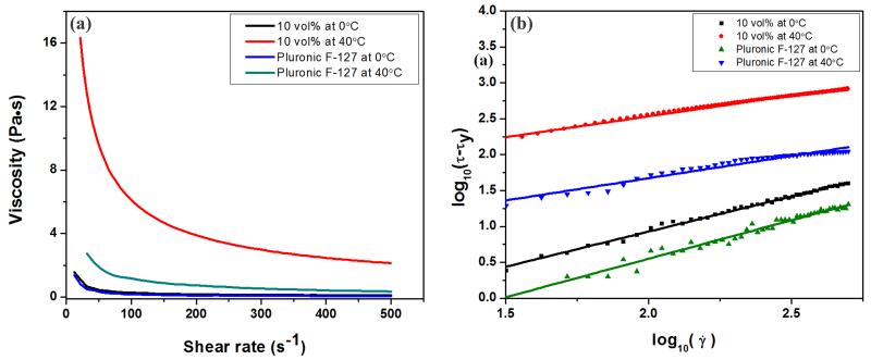
The rheological behavior of the F-127-based glass inks exhibited a strong dependence on temperature. At 0°C, glass suspension (10 vol% in 20 wt% F-127 solution) was stable and displayed Bingham plastic behavior. This stabilized suspension underwent a fluid-to-gel transition upon heating up to 40°C and exhibited shear-thinning behavior. The viscosity of the glass ink at 0°C and 40°C is shown in Figure 1a. For comparison, the viscosity of the F-127 suspension without glass particles at the same temperatures is also shown. The increase of the temperature from 0°C to 40°C not only markedly increased the viscosity of the ink at all shear rates but also changed their rheological properties from Bingham plastic to shear-thinning behavior; the addition of the glass resulted in a further increase in viscosity of the F-127 solution at 40°C, but not for these inks at 0°C.
Figure 1.
(a) Viscosity of the inks as a function of shear rate at 0°C and 40°C, respectively; (b) linear plot of log10(τ- τy) as a function of log10() for the inks. The lines are linear fits of the experimental data used to extract the Herschel-Bulkley viscosity parameters and exponent values in Table 1.
As F-127 is composed of poly(ethylene oxide) (PEO) – poly(propylene oxide) (PPO) – PEO triblocks, it is able to produce a low-viscosity aqueous solution at low temperature, while forming a gel at rising temperatures as a result of the release of water molecules bound to the hydrophobic PPO segments in the triblock[29]. At a low temperature, 0°C, the −OH groups in the PEO-PPO-PEO triblocks can bond to the surface of glass particles by van der Waals or hydrogen bonding providing stabilization by steric repulsion [28], resulting in the low viscosity of the glass inks. The sharp increase in the viscosity of the inks upon heating from 0°C to 40°C resulted from the phase transition of F-127 from aqueous solution to polymerized gel.
The rheology of the colloidal ink can be described by the Herschel-Bulkley model [28, 30]:
| (4) |
where τ is shear stress, τy is shear yield stress, is the shear rate, n is the flow index and k is the viscosity parameter. By fitting the curve of log (τ- τy) versus log (), shown in Figure1b, the values of τy, n and k are obtained and summarized in Table 1. At 0°C, n = 1.0 and τy = 15 and 19 Pa for inks with and without glass particles, respectively, indicating that the inks were Bingham fluids; at 40°C, n =0.62 and 0.58, τy = 67 and 250 Pa of the inks with and without glass particles, respectively, indicating their shear-thinning behavior. Gel-based inks with a shear-thinning behavior are reported to flow with a three-zone velocity profile within the cylindrical deposition nozzle. The profile consists of an unyielded (gel) core moving at a constant velocity surrounded by a yielded (fluid) shell experiencing laminar flow and a thin slip layer devoid of colloidal particles at the nozzle wall [31, 32]. The continuous deposition of rod-like filaments with a gelcore-fluid shell structure enables their shape retention while allowing the rods to fuse at their contact points.
Table 1.
Rheological properties of inks
| Temperature (°C) |
Glass concentration (vol%) |
τy (Pa) | k (Pa•Sn) | n |
|---|---|---|---|---|
| 0 | 0 | 15 | 0.03 | 1.0 |
| 0 | 10 | 19 | 0.1 | 1.0 |
| 40 | 0 | 67 | 2.7 | 0.62 |
| 40 | 10 | 250 | 24.0 | 0.58 |
The low viscosity of the inks at 0°C enabled the preparation of stable glass inks with higher particle concentration, up to 35 vol%. Data for the relative viscosity of the inks (shear rate = 100 s−1) as a function of glass particle concentration at 0°C and 40°C are shown in Figure 2. The particle concentration had a limited effect on the viscosity for volume fractions lower than ~30 vol% but above this value, the viscosity started to increase. The data can be well-fitted by a modified Krieger-Dougherty equation [33, 34]of the form:
| (5) |
with ηr, the relative viscosity, is defined as the viscosity of the suspension, η, divided by the viscosity of the solvent (20 wt% F-127 solution) ηL, ϕ is the volume fraction of the particles, ϕm is the volume fraction of particles at which the viscosity becomes practically infinite, and m is a fitting parameter. The maximum glass particle concentration in F-127 solution at 0°C predicted by this model was ϕm = 45 vol%, with n = 2.8; while for the solution at 40°C, ϕm = 40 vol%, with n = 3.2. To print structure with fine features (< 100 μm), glass inks with low viscosity were required to extrude through capillary nozzles. As the viscosity of the ink at 0°C increased sharply above ~35 vol%, the highest particle concentration used was 30 vol% for all the printing in this study.
Figure 2.
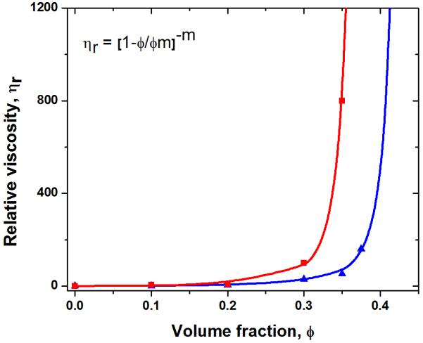
Relative viscosity of the inks at a shear rate of 100 s−1 versus volume fraction of glass particles at 0°C and 40°C, respectively.
Just as the viscosity of the paste is highly dependent on the temperature of the inks, so is the flow of the ink through the tip. As the printing process begins, ink flow is generated when a threshold stress is exceeded, after which a steady flow is achieved. A typical load-versus-displacement curve (Figure 3) exhibited two stages: (1) initial stabilization of the flow and (2) steady-state flow. Regardless of the ink composition, the increase of the temperature of the ink resulted in a significant increase of the load required for printing (from ~5 N at 0°C to > 10 N at 40°C). In contrast to the effects of temperature increases, the addition of 10 vol% glass particles to the F-127 ink does not significantly increase the threshold load. These findings correspond well with the rheological properties of the ink as discussed above, and indicate that the fluid-to-gel transition resulting from the temperature increase plays more important role in determining the flowability of the F-127-based ink.
Figure 3.
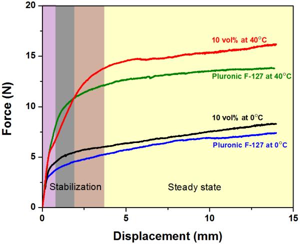
Load versus displacement curves for the inks printed through a 250 μm tip at 0°C and 40°C with a printing speed of 10 mm/s. Initially the system equilibrates and flow starts (shadowed zone) until a steady state is achieved.
3.2 Printing of glass scaffolds
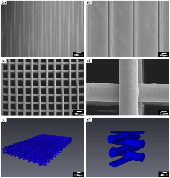
The low viscosity of stabilized glass ink facilitated printing through fine nozzles (down to 30 μm capillary tip, Figure 4a and b). Typically, when using micron-sized particles, the forces required to extrude the gel-like inks through narrow tips (<100 μm) cause water segregation and clogging of the nozzles [16]. Previous work has shown that 30 μm filaments can only be printed using inks containing BaTiO3 nanoparticles [35]. Here, the possibility of achieving the same fine- featured structure with micron-sized glass particles dispersed in a hydrogel-based ink is realized by simply controlling the temperature of the ink. The ease of processing the micro-sized ceramic ink enabled the printing of various ceramic powders into fine architectures.
Figure 4.
Patterns printed using the hydrogel-based glass ink: (a) as-printed parallel filaments using 30μm tip; and (b) high-magnification image of (a); (c) surface of the sintered glass scaffolds printed through a 100 μm nozzle with a spacing of 200 μm; (d) high-magnification image of (c); (e) 3-D visualization of the sintered 6P53B glass scaffolds using synchrotron X-ray micro computed tomography; and (f) a cut-away image of (e) to show the line fusion in the scaffold.
To achieve a filament span as large as 1–2 mm while maintaining high mechanical strength, tips with diameters of 100 or 250 μm were also used for the printing. Figure 4c shows a typical 3-D glass scaffold with precisely defined filament diameter, spacing, and number of layers patterned by extruding the glass ink through the 100 μm tip. The sintered periodical scaffold consisted of struts with diameters of 75 μm and pores of 200 μm. The softening point of the glass is ~610°C [25], and the scaffolds were subjected to a binder burnout process at 600°C for 2 hours. Next they were sintered at 700°C for 1 hour to densify the glass filament while avoiding crystallization or deformation of the structure. The sintering of the glass also led to the full densification of the glass rods and formation of strong bonds between the filaments ( Figure 4d). Three-dimensional visualization of the sintered glass scaffolds was achieved by synchrotron X-ray micro computed tomography (SR microCT). The scaffolds had uniform structure with well-bonded layers, as shown in Figure 4e and f. The constructs retained their shape with no noticeable deformation of the total structure after sintering (Figure 4e), while a solid fusion between the contact points of the filaments was formed (Figure 4f).
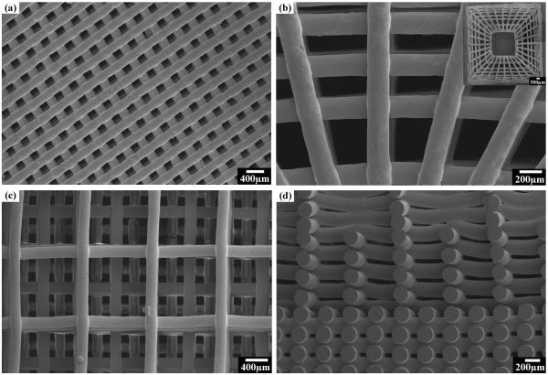
Scaffolds with custom-designed patterns were also successfully printed through a 250 μm nozzle into 3-D structures (Figure 5). Scaffolds with periodic grids (Figure 5a), anatomic cortical-trabecular structure (Figure 5b), and gradient porosity (Figure 5c and d) were fabricated, demonstrating the capability of the technique for the design and manufacturing of scaffolds with complex architecture. As bone consists of trabecular and cortical structures with the cortical bone primarily in the shaft of long bones and as the outer shell around trabecular bone [36], the ability to fabricate scaffolds with the anatomical structure and varied porosity may achieve desired mechanical response, and accelerate the healing of bone defects [37].
Figure 5.
Glass scaffolds of different patterns printed using the direct ink writing technique: (a) a glass scaffold with periodic pattern; (b) a glass scaffold with anatomic pattern composed of dense outerlayer and porous inner layers, with inset showing the gross view of the sintered scaffold; (c) surface view of a glass scaffold with gradient pore size; (d) cross sections of the same scaffold in (c).
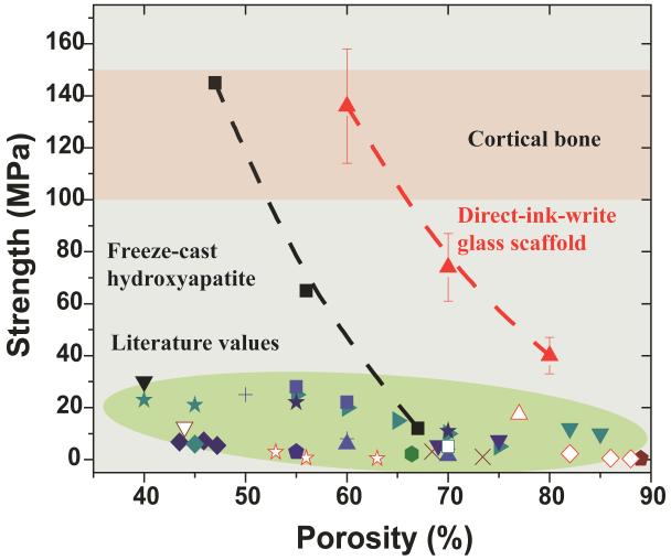
To determine the feasibility of using these scaffolds for the repair of load-bearing bone defects, their compressive strength (porosity 60 vol%, pore size 500 μm, rod diameter 100 μm, sintered at 700°C for 1 hour) in the directions parallel and perpendicular to the pore channels was tested. The compressive strength parallel to the pore channels was ~2.5 times of that measured in the perpendicular direction (136 MPa vs. 55 MPa), a reflection of the anisotropic structure of the scaffolds. This strength is within the range of that of human cortical bone (100-150 MPa) [38, 39]. This value is four- to five-times the strength obtained for the bioactive glass and hydroxyapatite scaffolds prepared by other conventional techniques [40], as shown in Figure 6. The elastic modulus, determined from the approximately linear region in the stress-strain curve, was 2.0 GPa, is also within the range of the value for trabecular bone (0.1 - 5 GPa) [38, 39]. The strength is also at least two orders of magnitude higher than that of the polymeric scaffolds [41]. The curve of compressive strength versus porosity of the glass scaffold shows a trend similar to that of the freeze-cast HA scaffolds consisting of unidirectional pores. The high mechanical strength of the freeze-cast scaffold is attributed to its anisotropic structure consisting of parallel ceramic lamellae [42, 43]. Anisotropic structure has been commonly observed in biological systems like wood, bone, cork, and glass sponge, and has been reported to be responsible for the ability to optimize efficiently the strength-to-density and stiffness-to-density ratio [44-46]. The work in this study might provide a new avenue for the fabrication of light-yet-strong materials.
Figure 6.
Compressive strength versus porosity of the glass scaffolds sintered at 700°C. Comparison with cortical and trabecular bone [38, 39] and literature values of porous glass and hydroxyapatite scaffolds. Each style of point corresponds to a different literature value; represents the data obtained in the present work on direct ink writing assembly of 6P53B glass;
  represents data obtained from freeze-casting of HA scaffolds [42].
At porosities up to 60 vol%, the strength of glass scaffolds (136 MPa) is significantly higher than that of the freeze-cast HA scaffolds (Figure 6). This might be a result of the complete densification of the glass rods and the periodic structure consisting of parallel channels.
3.3 In vitro degradation
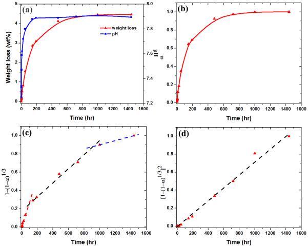
The in vitro reaction of the 6P53B glass scaffolds in SBF was monitored by measuring their weight loss and the pH of the solution. Figure 7(a) shows the weight loss of the 6P53B glass scaffolds as a function of immersion time in an SBF, which was used to monitor the conversion kinetics of the scaffolds to HA. The weight loss of the scaffold increased rapidly during the first 100 h of immersion, slowed between 100–400 h, and reached a nearly constant, limiting value above ~400 h. The limiting weight loss was 4.5 %. The change in pH of the SBF, resulting from the reactions accompanying the conversion of the glasses to HA, followed the same trend as the weight loss data (Figure 7a).
Figure 7.
(a) Weight loss of glass scaffolds, and pH of a simulated body fluid (SBF) as a function of immersion time; (b) fractional weight loss, α, as a function of immersion time; (c) isothermal dependences of versus immersion time compared with the prediction of a contraction volume model, CVM (dash lines); (d) isothermal dependences of versus immersion time compared with the prediction of a 3-D diffusion model (dash lines).
Under the assumption that ions such as Na+, K+, and (SiO4)4− dissolve in the solution, and that all the CaO in the glass reacts with the phosphate ions in the SBF to form an HA, Ca10(PO4)6(OH)2, the theoretical weight loss of 6P53B glass, ΔWtheo, is 68%. The small ΔWmeas values for the 6P53B glass scaffolds indicate its partial conversion. The weight-loss data were converted to a fractional weight loss, α, by dividing the measured weight loss by the measured maximum weight loss (4.5%)to monitor the conversion kinetics (Figure 7b). The data were compared with the predictions of models in an attempt to evaluate the mechanism of converting the glass scaffolds to HA (Figure 7c and d). While several models are available, depending on the assumed rate-controlling mechanism, the contracting volume model (CVM) and the 3-D diffusion model were selected because they describe processes relevant to the conversion of a bioactive glass to HA. These models have also been used to fit the conversion kinetics of 45S5 glass particles (150–300 μm) and 13-93 glass scaffolds to HA[27, 47]. The rate-controlling mechanisms determined for the conversion of these glasses are similar to those found in this work, which indicates that the geometry of the glass sample has little effect on the conversion mechanism.
The CVM assumes that the diffusion of ions is fast, so the reaction at the interface is rate-controlling. In this case, the thickness of the converted layer increases linearly with time. In the 3-D diffusion model, the diffusion of ions to the interface is rate-controlling, so the thickness of the converted layer increases with the square root of time. A spherical geometry is assumed in the model equations used in this study.
The isothermal dependences of and versus immersion time, t, are shown in Figure 7c and d, respectively. The fitting parameters are summarized in Table 2. Three stages in the conversion were observed in the CVM model during the immersion: (1) an initial fast dissolution stage in 0–100 h, (2) an intermediate stage in 100–400 h, and (3) a final stage in > 400 h. The kinetic parameters, k1, for these three stages were 2.8, 0.8 and 0.2 × 10⁻³, respectively. A larger value of k1 indicated the faster reaction at the interface and the rapid dissolution of the glass scaffolds. The 3-D diffusion model provided a good fit to the conversion kinetics of the 6P53B glass scaffold throughout the degradation process (Figure 7d), indicating that the conversion process was also controlled by diffusion of ions to the reaction interface. The kinetic value, k2, was determined to be 0.7 × 10⁻³ based on the curve fit
Table 2.
Kinetic parameters used for fitting the weight loss data
| Model | Reaction mechanism |
Integral form of the model |
Kinetic parameter, k (×10−3) |
|---|---|---|---|
| CVM | Contracting volume | 0-100 hr: 2.8 100-1000hr: 0.8 >1000 hr: 0.2 |
|
| 3-D diffusion | Three-dimensional diffusion |
0.7 |
The reaction of the bioactive glass scaffolds in SBF was controlled by both the dissolution of glass components (Na2O, K2O and SiO2) and the diffusion of Ca2+ from the inside of the glass to react with PO43− ions to form HA [4]. In the conversion of silicate bioactive glasses, a thin SiO2-rich layer (1–2 μm) first forms on the surface of the glass, which separates the unconverted glass from the precipitated HA. This layer moved inside the glass along with the conversion and acted as a barrier for the diffusion of the Ca2+ to the interface, which was in good agreement with the constant kinetic parameter in the 3-D diffusion model. The initial fast dissolution of the glass scaffold may be a result of the large ion concentration gradient and higher surface areas exposed in SBF. The CVM and 3-D diffusion model have also been used to fit the conversion kinetics of silicate 13-93 and borate-based glass scaffolds to HA [27]. The rate- controlling mechanisms determined for the conversion of these cellular-type glass scaffolds are similar to those found in this work.
During the conversion reaction, the increase in pH of the SBF with immersion time of the scaffolds (Figure 7a) showed trends similar to those for the weight loss data. This indicates that the same reactions are responsible for the conversion to HA and the pH increase. The increase in the pH resulted from the dissolution of the glass modifiers (Na+ and K+) and has been commonly observed for the bioactive glass reaction in SBF [27].
3.4 In vitro mechanical responses
The conversion of the glass to HA resulted in a decrease in the strength of the scaffolds (Fig. 8) from the initial 136 MPa to 77 MPa after immersion for three weeks in the SBF. As the glass filaments were the basic load-bearing units of the porous scaffolds, the decrease in strength might be explained in terms of the weight loss as a function of immersion time. The compressive strength is determined to be a function of the weight loss by the equation [27]:
| (7) |
where σoand σtare the compressive strengths of glass scaffolds before and after immersion in SBF for time t, ΔWtheo is the theoretical weight loss of the glass scaffolds, and n is the fitting parameter. The value of ΔWt was given by Figure 7a and ΔWtheo was 67.8%. As a result, n was found to be 9.0 for the scaffold. The theoretical compressive strengths were in good agreement with the experimental values (Figure 8). Although the strength decreased with the immersion time, the value was much higher than that for trabecular bone (2-12 MPa) after immersion for three weeks. Furthermore, the infiltration of the new bone into the scaffolds may increase their mechanical strength. Work is ongoing to evaluate mechanical strength following in vivo implantation in a rabbit femur segmental bone defect model.
Figure 8.
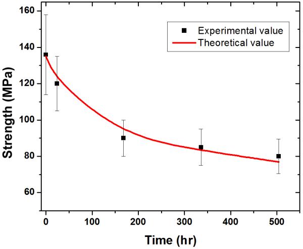
Compressive strength of the 6P53B glass as a function of immersion time in a simulated body fluid (SBF). The calculated strengths, based on the rate of degradation of the scaffolds in the SBF are shown as red lines.
4. Conclusion
Glass inks with controllable viscosity are developed by dispersing glass particles in a Pluronic® F-127 solution. The low viscosity of the ink at 0°C enables the printing of features as fine as 30 μm, while the high viscosity at 40°C retains the 3-D structure of the printed filaments. The sintered glass scaffolds show a compressive strength (136 ± 22 MPa) comparable to human cortical bone, while the porosity (60%) is in the range of trabecular bone. Despite the strength decrease during immersion in a simulated body fluid, the strength (77 MPa) value is still far above that of trabecular bone after three weeks. The results indicate the great potential of the 6P53B glass scaffolds in the repair and regeneration of load-bearing bone defects.
Acknowledgements
This work was supported by the National Institutes of Health/National Institute of Dental and Craniofacial Research (NIH/NIDCR) Grant No. 1 R01 DE015633. We acknowledge support of the dedicated X-ray tomography beamline 8.3.2 at the Advanced Light Source (ALS), funded by Department of Energy under Contract No. DE-AC02-05CH11231. ES is grateful for the support from EPRSC. QF thanks Xin Liu and Dr. Mohamed N. Rahaman at Missouri University of Science and Technology for the viscosity measurement and helpful discussions.
Footnotes
Publisher's Disclaimer: This is a PDF file of an unedited manuscript that has been accepted for publication. As a service to our customers we are providing this early version of the manuscript. The manuscript will undergo copyediting, typesetting, and review of the resulting proof before it is published in its final citable form. Please note that during the production process errors may be discovered which could affect the content, and all legal disclaimers that apply to the journal pertain.
References
- [1].Hench LL, Polak JM. Third-generation biomedical materials. Science. 2002;295:1014–7. doi: 10.1126/science.1067404. [DOI] [PubMed] [Google Scholar]
- [2].Hench LL, Wilson J. Surface-Active Biomaterials. Science. 1984;226:630–6. doi: 10.1126/science.6093253. [DOI] [PubMed] [Google Scholar]
- [3].Wheeler DL, Stokes KE, Park HM, Hollinger JO. Evaluation of particulate Bioglass(R) in a rabbit radius ostectomy model. J Biomed Mater Res. 1997;35:249–54. doi: 10.1002/(sici)1097-4636(199705)35:2<249::aid-jbm12>3.0.co;2-c. [DOI] [PubMed] [Google Scholar]
- [4].Hench LL. Bioceramics. J Am Ceram Soc. 1998;81:1705–28. [Google Scholar]
- [5].Xynos ID, Edgar AJ, Buttery LDK, Hench LL, Polak JM. Gene-expression profiling of human osteoblasts following treatment with the ionic products of Bioglass® 45S5 dissolution. J Biomed Mater Res. 2001;55:151–7. doi: 10.1002/1097-4636(200105)55:2<151::aid-jbm1001>3.0.co;2-d. [DOI] [PubMed] [Google Scholar]
- [6].Leach JK, Kaigler D, Wang Z, Krebsbach PH, Mooney DJ. Coating of VEGF-releasing scaffolds with bioactive glass for angiogenesis and bone regeneration. Biomaterials. 2006;27:3249–55. doi: 10.1016/j.biomaterials.2006.01.033. [DOI] [PubMed] [Google Scholar]
- [7].Leu A, Leach JK. Proangiogenic potential of a collagen/bioactive glass substrate. Pharm Res. 2008;25:1222–9. doi: 10.1007/s11095-007-9508-9. [DOI] [PubMed] [Google Scholar]
- [8].Chen QZZ, Thompson ID, Boccaccini AR. 45S5 Bioglass®-derived glass-ceramic scaffolds for bone tissue engineering. Biomaterials. 2006;27:2414–25. doi: 10.1016/j.biomaterials.2005.11.025. [DOI] [PubMed] [Google Scholar]
- [9].Fu Q, Rahaman MN, Bal BS, Brown RF, Day DE. Mechanical and in vitro performance of 13-93 bioactive glass scaffolds prepared by a polymer foam replication technique. Acta Biomater. 2008;4:1854–64. doi: 10.1016/j.actbio.2008.04.019. [DOI] [PubMed] [Google Scholar]
- [10].Jones JR, Ehrenfried LM, Hench LL. Optimising bioactive glass scaffolds for bone tissue engineering. Biomaterials. 2006;27:964–73. doi: 10.1016/j.biomaterials.2005.07.017. [DOI] [PubMed] [Google Scholar]
- [11].Fu Q, Rahaman MN, Bal BS, Brown RF. Preparation and in vitro evaluation of bioactive glass (13-93) scaffolds with oriented microstructures for repair and regeneration of load-bearing bones. J Biomed Mater Res A. 2010;93A:1380–90. doi: 10.1002/jbm.a.32637. [DOI] [PubMed] [Google Scholar]
- [12].Rahaman MN, Day DE, Sonny Bal B, Fu Q, Jung SB, Bonewald LF, et al. Bioactive glass in tissue engineering. Acta Biomater. 2011;7:2355–73. doi: 10.1016/j.actbio.2011.03.016. [DOI] [PMC free article] [PubMed] [Google Scholar]
- [13].Fu Q, Saiz E, Rahaman MN, Tomsia AP. Bioactive glass scaffolds for bone tissue engineering: State of the art and future perspective. Mat Sci Eng C. 2011 doi: 10.1016/j.msec.2011.04.022. In press. [DOI] [PMC free article] [PubMed] [Google Scholar]
- [14].Gratson GM, Xu MJ, Lewis JA. Microperiodic structures - Direct writing of three-dimensional webs. Nature. 2004;428:386. doi: 10.1038/428386a. [DOI] [PubMed] [Google Scholar]
- [15].Ahn BY, Duoss EB, Motala MJ, Guo XY, Park SI, Xiong YJ, et al. Omnidirectional Printing of Flexible, Stretchable, and Spanning Silver Microelectrodes. Science. 2009;323:1590–3. doi: 10.1126/science.1168375. [DOI] [PubMed] [Google Scholar]
- [16].Franco J, Hunger P, Launey ME, Tomsia AP, Saiz E. Direct write assembly of calcium phosphate scaffolds using a water-based hydrogel. Acta Biomater. 2010;6:218–28. doi: 10.1016/j.actbio.2009.06.031. [DOI] [PMC free article] [PubMed] [Google Scholar]
- [17].Lewis JA, Smay JE, Stuecker J, Cesarano J. Direct ink writing of three-dimensional ceramic structures. J Am Ceram Soc. 2006;89:3599–609. [Google Scholar]
- [18].Hoelzle DJ, Alleyne AG, Johnson AJW. Micro-robotic deposition guidelines by a design of experiments approach to maximize fabrication reliability for the bone scaffold application. Acta Biomater. 2008;4:897–912. doi: 10.1016/j.actbio.2008.02.018. [DOI] [PubMed] [Google Scholar]
- [19].McIntosh L, Cordell JM, Johnson AJW. Impact of bone geometry on effective properties of bone scaffolds. Acta Biomater. 2009;5:680–92. doi: 10.1016/j.actbio.2008.09.010. [DOI] [PubMed] [Google Scholar]
- [20].Hollister SJ. Porous scaffold design for tissue engineering. Nat Mater. 2005;4:518–24. doi: 10.1038/nmat1421. [DOI] [PubMed] [Google Scholar]
- [21].Michna S, Wu W, Lewis JA. Concentrated hydroxyapatite inks for direct-write assembly of 3-D periodic scaffolds. Biomaterials. 2005;26:5632–9. doi: 10.1016/j.biomaterials.2005.02.040. [DOI] [PubMed] [Google Scholar]
- [22].Miranda P, Saiz E, Gryn K, Tomsia AP. Sintering and robocasting of beta-tricalcium phosphate scaffolds for orthopaedic applications. Acta Biomater. 2006;2:457–66. doi: 10.1016/j.actbio.2006.02.004. [DOI] [PubMed] [Google Scholar]
- [23].Smay JE, Gratson GM, Shepherd RF, Cesarano J, Lewis JA. Directed colloidal assembly of 3D periodic structures. Adv Mater. 2002;14:1279–83. [Google Scholar]
- [24].Pazo A, Saiz E, Tomsia AP. Silicate glass coatings on Ti-based implants. Acta Mater. 1998;46:2551–8. [Google Scholar]
- [25].Lopez-Esteban S, Gutierrez-Gonzalez CF, Gremillard L, Saiz E, Tomsia AP. Interfaces in graded coatings on titanium-based implants. J Biomed Mater Res A. 2009;88A:1010–21. doi: 10.1002/jbm.a.31935. [DOI] [PMC free article] [PubMed] [Google Scholar]
- [26].Russias J, Saiz E, Deville S, Gryn K, Liu G, Nalla RK, et al. Fabrication and in vitro characterization of three-dimensional organic/inorganic scaffolds by robocasting. J Biomed Mater Res A. 2007;83A:434–45. doi: 10.1002/jbm.a.31237. [DOI] [PubMed] [Google Scholar]
- [27].Fu Q, Rahaman MN, Fu HL, Liu X. Silicate, borosilicate, and borate bioactive glass scaffolds with controllable degradation rate for bone tissue engineering applications. I. Preparation and in vitro degradation. J Biomed Mater Res A. 2010;95A:164–71. doi: 10.1002/jbm.a.32824. [DOI] [PubMed] [Google Scholar]
- [28].Rahaman MN. Ceramic processing. CRC/Taylor & Francis; Boca Raton, FL: 2007. [Google Scholar]
- [29].Cohn D, Sosnik A, Garty S. Smart hydrogels for in situ generated implants. Biomacromolecules. 2005;6:1168–75. doi: 10.1021/bm0495250. [DOI] [PubMed] [Google Scholar]
- [30].Herschel WH, Bulkley R. Konsistenzmessungen von Gummi-Benzollosungen. Kolloid Z. 1926;39:291. [Google Scholar]
- [31].Buscall R, Mcgowan JI, Mortonjones AJ. The Rheology of Concentrated Dispersions of Weakly Attracting Colloidal Particles with and without Wall Slip. J Rheol. 1993;37:621–41. [Google Scholar]
- [32].Kalyon DM, Yaras P, Aral B, Yilmazer U. Rheological Behavior of a Concentrated Suspension - a Solid Rocket Fuel Simulant. J Rheol. 1993;37:35–53. [Google Scholar]
- [33].Krieger IM, Dougherty TJ. A Mechanism for Non-Newtonian Flow in Suspensions of Rigid Spheres. T Soc Rheol. 1959;3:137–52. [Google Scholar]
- [34].Bergstrom L. Shear thinning and shear thickening of concentrated ceramic suspensions. Colloid Surface A. 1998;133:151–5. [Google Scholar]
- [35].Li Q, Lewis JA. Nanoparticle inks for directed assembly of three-dimensional periodic structures. Adv Mater. 2003;15:1639–43. [Google Scholar]
- [36].Martin RB, Burr DB, Sharkey NA. Skeletal tissue mechanics. Springer; New York: 1998. [Google Scholar]
- [37].Hollister SJ. Porous scaffold design for tissue engineering. Nat Mater. 2006;5:590. doi: 10.1038/nmat1421. (vol 4, pg 518, 2005) [DOI] [PubMed] [Google Scholar]
- [38].Rho JY, Hobatho MC, Ashman RB. Relations of Mechanical-P roperties to Density and Ct Numbers in Human Bone. Med Eng Phys. 1995;17:347–55. doi: 10.1016/1350-4533(95)97314-f. [DOI] [PubMed] [Google Scholar]
- [39].Fung YC. Biomechanics: mechanical properties of living tissues. 2nd ed. Springer-Verlag; New York; London: 1993. [Google Scholar]
- [40].Fu Q, Saiz E, Tomsia AP. Bio-inspired Highly Porous and Strong Glass Scaffolds. Adv Funct Mater. 2011;21:1058–63. doi: 10.1002/adfm.201002030. [DOI] [PMC free article] [PubMed] [Google Scholar]
- [41].Rezwan K, Chen QZ, Blaker JJ, Boccaccini AR. Biodegradable and bioactive porous polymer/inorganic composite scaffolds for bone tissue engineering. Biomaterials. 2006;27:3413–31. doi: 10.1016/j.biomaterials.2006.01.039. [DOI] [PubMed] [Google Scholar]
- [42].Deville S, Saiz E, Nalla RK, Tomsia AP. Freezing as a path to build complex composites. Science. 2006;311:515–8. doi: 10.1126/science.1120937. [DOI] [PubMed] [Google Scholar]
- [43].Munch E, Launey ME, Alsem DH, Saiz E, Tomsia AP, Ritchie RO. Tough, Bio-Inspired Hybrid Materials. Science. 2008;322:1516–20. doi: 10.1126/science.1164865. [DOI] [PubMed] [Google Scholar]
- [44].Ashby MF, Gibson LJ, Wegst U, Olive R. The Mechanical-Properties of Natural Materials .1. Material Property Charts. P Roy Soc Lond a Mat. 1995;450:123–40. [Google Scholar]
- [45].Gibson LJ, Ashby MF. Cellular solids : structure and properties. 2nd ed. Cambridge University Press; Cambridge ; New York: 1999. [Google Scholar]
- [46].Fratzl P, Weinkamer R. Nature’s hierarchical materials. Prog Mater Sci. 2007;52:1263–334. [Google Scholar]
- [47].Jung SB, Day DE. Conversion kinetics of silicate, borosilicate and borate glasses to hydroxyapatite. Phys Chem Glass: Eur J Glass Sci Technol B. 2009;50:85–8. [Google Scholar]


