Abstract
Chemotaxis allows bacteria to approach sources of attractant chemicals or to avoid sources of repellent chemicals. Bacteria constantly monitor the concentration of specific chemoeffectors by comparing the current concentration to the concentration detected a few seconds earlier. This comparison determines the net direction of movement. Although multiple, competing gradients often coexist in nature, conventional approaches for investigating bacterial chemotaxis are suboptimal for quantifying migration in response to concentration gradients of attractants and repellents. Here, we describe the development of a microfluidic chemotaxis model for presenting precise and stable concentration gradients of chemoeffectors to bacteria and quantitatively investigating their response to the applied gradient. The device is versatile in that concentration gradients of any desired absolute concentration and gradient strength can be easily generated by diffusive mixing. The device is demonstrated using the response of Escherichia coli RP437 to gradients of amino acids and nickel ions.
Protocol
1. Fabrication of silicon masters using standard SU-8 photolithography1(not shown in this video).
Use standard SU-8 photolithography methods to create a SU-8 "master" (SU-8 2025, MicroChem, Newton, MA) for fabricating the PDMS mold that contains the microfluidic network and chemotaxis chamber. Such master molds can be fabricated at any microfabrication facility (e.g., Stanford Microfluidics Foundry; http://thebigone.stanford.edu/foundry/).
Prior to PDMS replication, expose the SU-8 master to fluorosilane vapor in a desiccator attached to a vacuum source to facilitate easy release of PDMS from the master. Add a drop of fluorosilane to a paper towel and apply vacuum for one min. Remove the vacuum and allow 30 min for deposition of fluorosilane. Keep the SU-8 master in a closed container for future use.
2. Replica molding of PDMS from SU-8 master: The fluidic layer and the control layer are made by replica molding of PDMS from SU-8 master.
Mix the PDMS pre-polymer and cross-linker at a 10:1 wt. ratio and degas in a dessicator for 1 hour (or until air bubbles are removed from the PDMS mixture).
Place the SU-8 master in a petri dish and carefully pour the PDMS mixture on top of the SU-8 master to the desired thickness.
Heat the petri dish containing the PDMS and the SU-8 master mold at 80°C for two hours to cure the PDMS.
Remove the cured PDMS-covered SU-8 master from the hotplate and peel the PDMS mold from the SU-8 master. The desired structure will be embedded in the PDMS mold.
Punch holes in the PDMS mold for tubing to the gradient generator and cell inlet using a 20 gauge blunt-end needle.
3. Bonding of PDMS devices:
Clean a glass microscope slide with isopropanol and dry with nitrogen or an air stream.
Expose the PDMS and glass slide to oxygen plasma in a plasma asher.
Bring the PDMS mold into contact with the glass slide. Heat the contacted slide and PDMS mold to 65°C for 15 min.
4. Assembling the PDMS device
Using a razor blade, cut tubing at a 45° angle to the correct length required for the device.
Insert one end of the tubing into the holes punched in the device (e.g., outlet) using forceps.
Using forceps, insert a blunt 30-gauge needle into the other end of the tubing.
Repeat step 4.2 for all the remaining holes.
Collect 1mL of chemotaxis buffer (CB) in a 3mL syringe, taking care to remove air bubbles from the syringe.
Fix a needle hub to one end of the outlet tubing.
Add CB to the needle hub, and tap the needle hub to remove any air bubbles.
Push a little CB out of the tip of the syringe and connect the 3mL syringe to the needle hub without trapping air.
Push CB through the device until all remaining needle hubs are filled with with CB. This should remove a majority of the air bubbles.
Fill two 500μL syringes with CB containing the appropriate concentrations of the chemoeffector being tested. Eliminate air bubble formation by pushing out a small drop of the syringe contents and touching the drop to the liquid in the needle hub and attaching.
Similarly, connect a syringe containing CB to the bacteria inlet. This will be removed when bacteria are introduced into the device.
5. Growth of highly motile E. coli
Grow overnight cultures of E. coli RP437 with a GFP expression plasmid in 20 mL of tryptone broth (TB) at 32°C with shaking. Add appropriate concentrations of antibiotic to maintain the plasmid. In our protocol, we use a low-copy plasmid pCM182 for detecting bacteria based on fluorescence in the device. For E. coli, growing cultures at 32°C is recommended for high motility, as motility is lower at higher temperatures.
Use the overnight culture to inoculate a 20 mL culture of TB in a 250 mL Erlenmeyer flask to an optical density at 600nm of ~ 0.05. Grow the culture with shaking at 32°C.
Harvest the cells at an OD600 of ~0.35 0.45 by low-speed centrifugation at 400 x g for 5 min.
Resuspend cells to an OD600 of ~0.35 in CB containing the chemoeffector at the concentration expected in the middle of the channel.
Add RFP-labeled dead cells at an OD600 of ~ 0.35 to the GFP-expressing live cells. The dead (red) cells are used as an internal control to ensure that any migration is not due to flow effects.
6. Monitoring chemotaxis
Remove some of the CB from the cell inlet needle hub. Refill with the cell suspension.
Gently fill the 50μL syringe with the resuspended cells. This step needs to be done slowly as flagella can be sheared and will reduce motility.
Attach the 50μL syringe to the inlet-needle hub as described in steps step 4.10.
Position the device on the stage of a fluorescence microscope equipped with a high-speed camera for image acquisition. Place the inlet syringes (both the 500 μL gradient syringes and the 50 μL cell syringe) into the syringe pump and initiate flow such that the gradient is formed and cells are flowing through the tubing.
Once cells enter the chemotaxis chamber, wait ~ 20 min for the system to stabilize before imaging.
Collect green (live) and red (dead) fluorescence images at different locations along the length of the chamber (corresponding to different exposure times). Typically, we collect 100 images at each location at 3 sec intervals.
7. Data analysis: The following steps can be performed using any commercially available image analysis program (e.g., ImageJ, Metamorph) or using simple codes written in Matlab.
Remove the background pixels in the image (i.e., set threshold pixel intensity and remove all pixels that have intensity less than the threshold). This minimizes noise in the analysis.
Use the position of the dead cells (red fluorescence) to determine the center of the image. Since the dead cells show no chemotaxis, this represents the position where cells entered the chemotaxis chamber and would be detected in the absence of any migration.
Locate live cells (green fluorescence) in the image.
Divide the image into channels and determine the number of live cells in each channel. In our prior work3, the 1050 μm wide chemotaxis chamber was divided into 64 channels that are each ~ 16 μm wide.
Repeat steps 7.1 7.3 for all images and sum the total cell counts for each channel across all images. This gives the total cell count detected at each channel over the duration of the experiment.
Calculate the chemotaxis partition coefficient (CPC), which represents the direction of migration, as follows: Each cell located in the high concentration (right) and low concentration (left) sides of the dead cells is assigned a multiplier of +1 and -1, respectively. That is, a cell that migrates up a gradient is multiplied by +1 while cells moving down the gradient are multiplied by -1. All the multiplied values are added up and normalized to the total number of detected cells. For example, a CPC value of 0.40 indicates that 40% more of the total bacteria moved to the high concentration side than the low concentration side (i.e., the chemoeffector is an attractant as more bacteria were detected moving up the gradient).
Calculate the chemotaxis migration coefficient (CMC), which weighs the migration of cells by the distance travelled, as follows: Weight the cell count in each channel by a factor that is proportional to the distance that cells migrate. A cell that moves to the farthest high-concentration position (channel 64) is given a weighting factor of +1, whereas one that moves halfway into the higher concentration side is given a weighting factor of +0.5, and a cell moving to the farthest low-concentration position is weighted by -1. Sum up all the weighted cell counts and normalize to the number of cells to generate the CMC.
Representative Results3,4:
We have used the microfluidic device (Figure 1A) described here to investigate chemotaxis of E. coli in gradients of attractants (aspartic acid, autoinducer-2) and repellents (NiSO4, indole)3,4. The prototypical chemotaxis strain5E. coli RP437 expressing GFP was used, along with kanamycin-killed E. coli TG1 cells expressing red fluorescent protein to monitor flow effects. The concentration gradient formed in the μFlow device is shown in Figure 1B. The cell inlet was capped so that there was no flow through it and a stable gradient of 0 100 ng/mL of fluoresscein was established in the device. The pixel intensity across the device was used to determine the concentration profile of fluorescein. The data show that bacteria encounter a linear gradient when they enter the chemotaxis chamber. Figure 2A and B shows fluorescence images of E. coli RP437 migrating in response to gradients of aspartic acid (0 100 μM) and NiSO4 (0 225 μM). The observed responses to these canonical attractant and repellent are as predicted. Figure 3A shows the quantified distribution of E. coli RP437in the absence of a concentration gradient (i.e., null gradient of aspartic acid), while Figures 3B and C show the distribution in gradients of aspartic acid and NiSO4. The specificity of these responses (i.e., the bias in migration) is evident as a E. coli RP437 Δtar strain (i.e., strain lacking the Tar chemoreceptor that is used in E. coli to sense aspartic acid and nickel) does not demonstrate the bias in migration in the presence of a concentration gradient of aspartic acid or NiSO4. The trends evident in the spatial distribution profiles are also consistent with the calculated CPC and CMC values. The CPC values for the migration of E. coli RP437 in gradients of aspartic acid or NiSO4 are +0.33 and -0.33, respectively. The corresponding CMC values are +0.13 and -0.14, respectively. In contrast, the CPC and CMC values with the E. coli RP437 Δtar strain in gradients of aspartic acid or NiSO4 are negligible. In addition, the CPC and CMC in a null gradient of aspartic acid are +0.03 and +0.02, respectively, and indicate the lack of bias in migration in the absence of a gradient.
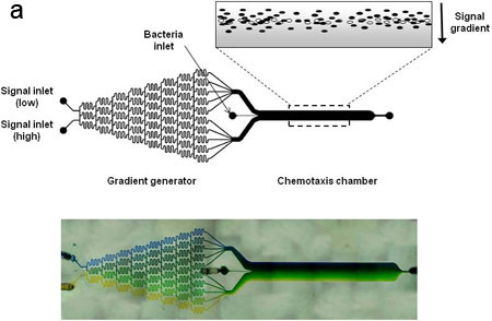
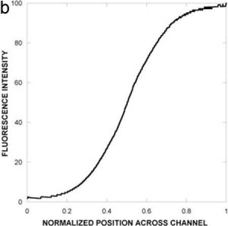 Figure 1. Device schematic and concentration gradient.
(A) Schematic representation of the microfluidic chemotaxis device. The device consists of a gradient-mixing module (20 x 100 x 18750 μm) and a chemotaxis observation module (20 x 1050 x 11500 μm). The widths of the two gradient channels entering the device are 500 μm and the width of the bacteria inlet is 50 μm. The inset depicts a gradient of signaling molecule (grey) and bacteria migrating in response to it. Live bacteria are depicted as solid ovals, whereas dead bacteria are shown as open ovals. (B) A concentration gradient between 0 and 100 ng/mL fluorescein was generated in the device and imaged using fluorescence microscopy. Fluorescence images were acquired after 30 min and quantified by image analysis.
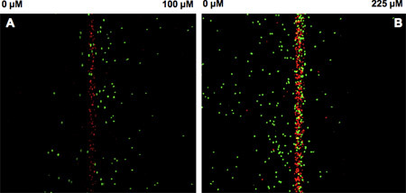 Figure 2. Chemotaxis of E. coli RP437 in the microfluidic device.
E. coli RP437 was exposed to a gradient of (A) 0-100 μM L-aspartate or (B) 0-225 μM NiSO4 in the device and the migration of live bacteria (green) towards L-aspartate or away from nickel imaged every 2.5 sec for 30 min. Dead bacteria (red) served as the control for flow effects in the device. Images were quantified using an in-house developed analysis program3. Data shown are representative pseudo-colored images from three independent experiments.
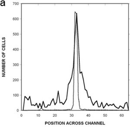
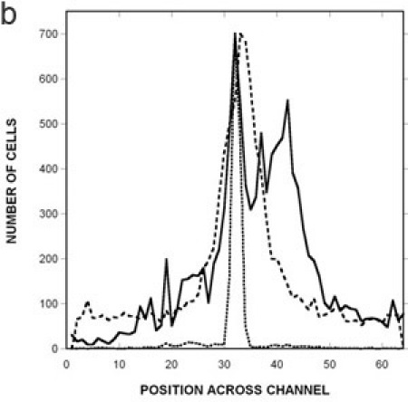
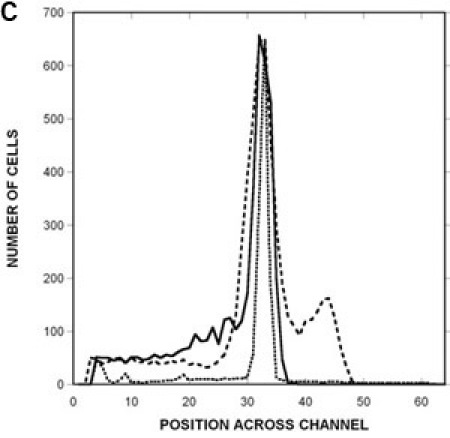 Figure 3: Quantification of migration profiles to a canonical attractant and repellent.
Spatial distribution of RP437 in the microfluidic device in response to (A) uniform 100 μM L-aspartate (i.e., no gradient), (B) a 0 100 μM gradient of aspartate, and (C) a 0 225 μM gradient of NiSO4. The distribution of dead cells is shown as a solid line, the distribution of RP437 cells is shown as a dashed line, and the distribution of RP437 eda+ Δtar cells is shown as a dotted line. Data shown are averaged for three independent experiments.
Discussion
The chemotaxis partition coefficient (CPC) and the chemotaxis migration coefficient (CMC) can be calculated as described in Mao et al5. If a cell is detected on the high concentration side, it is given a value of +1, whereas a cell detected on the low concentration side is given a value of -1. The values are summed up and divided by the total number of cells to generate the CPC. The sign of the CPC (positive or negative) gives the direction of migration (towards or away from a signal). Although the CPC indicates whether cells respond to a chemical as an attractant or repellent, it does not quantify the extent of the chemotaxis. For this, we calculate the CMC by dividing the spatial distribution profile of bacteria across the width of the device into 64 sections (32 on each side of the cell inlet), and assigning a weighting factor to cells in each section based on the distance of migration. The sections farthest from the center (sections 1 and 64) are multiplied by +1 (= 31.5/31.5) or -1 since they contain cells that have migrated the maximum distance. The next two sections (2 and 63) are multiplied by +0.968 (= 30.5/31.5) or -0.968. The last two sections (i.e., 32 and 33 that are closest to the cell inlet) are multiplied by + 0.015 (= 0.5/31.5) or -0.015. The weighted values are summed and normalized to the total number of cells to generate the CMC. A CMC of +1 indicates that all the bacteria moved completely up the gradient to the wall of the flow chamber. In the case of a mild attractive response, the CMC would still be a positive, but have a smaller value, whereas the CPC value would still be +1. Thus the CMC discriminates responsive cells based on the extent of migration.
Certain parameters need to be carefully controlled while performing chemotaxis experiments. The temperature at which the bacteria are cultivated is important. For E. coli, we have observed that the best growth temperature is 32°C and higher temperatures reduce motility. For certain receptors to be present in bacteria, it may be necessary to grow the bacteria in the presence of an inducing chemoeffector (i.e., to prime the cells for chemotaxis). For example, when investigating the response of bacteria to maltose, cells are grown with 0.1% (w/v) of the sugar. When resuspending the bacteria after centrifugation, it is important that gentle shaking/rolling of the tube is performed and the cells are not vortexed. Vigorous shaking can shear the flagella and reduce the motility of the cells being tested. The flow rates used in the device will need to be determined based on the motility of the bacterium being tested. Slower flow rates may be required for bacteria that are less motile, and the optimal flow rate must be determined empirically.
We anticipate that the μFlow device can be used for fundamental investigations on bacterial chemotaxis (e.g., competition between chemoeffectors for the same receptor) as well as in identifying bacteria in environmental samples that respond to particular chemicals as attractants or repellents.
Acknowledgments
This work was supported in part by the National Science Foundation (CBET 0846453).
References
- McDonald JC. Prototyping of microfluidic devices in poly(dimethylsiloxane) using solid-object printing. Anal Chem. 2002;74:1537–1545. doi: 10.1021/ac010938q. [DOI] [PubMed] [Google Scholar]
- Hansen MC, Palmer RJJ, Udsen C, White DC, Molin S. Assessment of GFP fluorescence in cells of Streptococcus gordonii under conditions of low pH and low oxygen concentration. Microbiol. 2001;147:1383–1391. doi: 10.1099/00221287-147-5-1383. [DOI] [PubMed] [Google Scholar]
- Englert DL, Manson MD, Jayaraman A. A Flow-Based Microfluidic Device for Quantifying Bacterial Chemotaxis in Stable, Competing Gradients. Appl Environ Microbiol. 2009;75:4557–4564. doi: 10.1128/AEM.02952-08. [DOI] [PMC free article] [PubMed] [Google Scholar]
- Englert DL, Jayaraman A, Manson MD. Microfluidic techniques for the analysis of bacterial chemotaxis. Humana press; 2009. [DOI] [PubMed] [Google Scholar]
- Mao H, Cremer PS, & Manson. A sensitive, versatile microfluidic assay for bacterial chemotaxis. PNAS. 2003;100(9):5449–5454. doi: 10.1073/pnas.0931258100. [DOI] [PMC free article] [PubMed] [Google Scholar]


