

Abstract
Prompted by recent reports suggesting that interaction of filamin A (FLNa) with its binding partners is regulated by mechanical force, we examined mechanical properties of FLNa domains using magnetic tweezers. FLNa, an actin cross-linking protein, consists of two subunits that dimerize through a C-terminal self-association domain. Each subunit contains an N-terminal spectrin-related actin-binding domain followed by 24 immunoglobulinlike (Ig) repeats. The Ig repeats in the rod 1 segment (repeats 1–15) are arranged as a linear array, whereas rod 2 (repeats 16–23) is more compact due to interdomain interactions. In the rod 1 segment, repeats 9–15 augment F-actin binding to a much greater extent than do repeats 1–8. Here, we report that the three segments are unfolded at different forces under the same loading rate. Remarkably, we found that repeats 16–23 are susceptible to forces of ∼10 pN or even less, whereas the repeats in the rod 1 segment can withstand significantly higher forces. The differential force response of FLNa Ig domains has broad implications, since these domains not only support the tension of actin network but also interact with many transmembrane and signaling proteins, mostly in the rod 2 segment. In particular, our finding of unfolding of repeats 16–23 at ∼10 pN or less is consistent with the hypothesized force-sensing function of the rod 2 segment in FLNa.
Introduction
Filamin A (FLNa) is an elongated homodimeric protein that can cross-link actin filaments into orthogonal networks and is essential for cell mechanics mediated by myosin contraction (1–4). FLNa is also a binding scaffold for numerous cellular proteins of great functional diversity (2,5). Each FLNa subunit has an N-terminal spectrin-related actin-binding domain followed by 24 immunoglobulin (Ig) repeats (IgFLNa 1–24) (6). Two intervening hinges separate the Ig repeats into rod 1 (repeats 1–15), rod 2 (repeats 16–23), and the self-association domain (repeat 24) (Fig. 1 A). In addition to the N-terminal actin binding domain, repeats 9–15 in rod 1 also interact with actin, becoming the secondary actin-binding sites, whereas the other Ig domains do not (3). A remarkable structural difference between the two segments is that rod 2 is a compact structure, whereas rod 1 is an extended linear array (6). Recent publications have revealed that the compact IgFLNa 16–23 is caused by interdomain interactions: domains 16 and 17, 18 and 19, and 20 and 21 form stable paired structures (7,8). It is intriguing that domain pair 20-21, for example, masks the binding site on IgFLNa21 for the integrin cytoplasmic tail (7,8). A recent fully atomistic molecular dynamics simulation showed that mechanical force can expose the cryptic integrin-binding site on IgFLNa21, suggesting a force-regulated integrin-FLNa interaction (9). Proteins binding to other domain pairs in IgFLNa 16–23 likely adopt the same mechanism.
Figure 1.
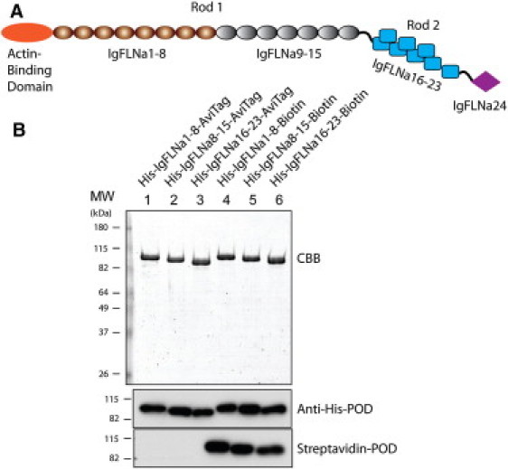
(A) Schematic structure of the FLNa monomer. The rod 1 segment contains domains IgFLNa 1–15 and the rod 2 segment contains domains IgFLNa 16–23. (B) SDS-PAGE gel of purified proteins used in this study. Proteins were stained with Coomassie brilliant blue (CBB) and detected by anti-His antibody and streptavidin conjugated with peroxidase (POD).
The force response of FLNa is physiologically important, since in vivo FLNa is subject to mechanical force transmitted from network of actin filaments. It has been shown in vitro that under large deformations, F-actin networks soften at low FLNa concentrations and strain-harden at high FLNa concentrations (4). This result suggests that the mechanical property of FLNa may affect the rheological and mechanical properties of F-actin networks.
The force response of full-length FLNa was studied by atomic force microscopy (AFM) (10). Under a pulling rate of 0.37 μm/s, the unfolding force was found to be in the range 50–200 pN, and the distribution of unfolding forces showed three peaks (10). However, due to the differences in function and structure among the different segments in FLNa, it is necessary to study the differential force response of IgFLNa 1–8, 9–15, and 16–23 to understand their possible force-dependent functions. In addition, the mechanical stability of these segments under much lower loading rates or under constant force is important, since the deformation of F-actin networks in vivo takes place on a much slower timescale. For example, the cell protrusion-retraction cycle was reported to occur at a period of ∼24 s (11). Most important, many binding partners of FLNa target domains in the rod 2 segment, and their binding affinity is likely dependent on the force applied to IgFLNa 16–23. To date, however, the force response of IgFLNa 16–23 has not been directly investigated by experiment.
Here, we report what to our knowledge is the first study of the differential force response of FLNa segments: IgFLNa 1–8, IgFLNa 8–15, and IgFLNa 16–23 using a magnetic-tweezers setup under low loading rate or constant force. We use IgFLNa 8–15 instead of IgFLNa 9–15 to have equivalent numbers of Ig repeats to IgFLNa 1–8 and 16–23. A difference in mechanical stability has been observed among IgFLNa 1–8, 8–15, and 16–23. Most important, some domains in FLNa 16–23 are susceptible to forces of ∼10 pN or even less, which are comparable to in vivo forces that can be generated by one or a few myosins (12). For comparison, domains in IgFLNa 1–8 and IgFLNa 8–15 can withstand much higher forces (∼20 pN or above).
Materials and Methods
Three protein constructs of FLNa segments, IgFLNa 1–8, IgFLNa 8–15, and IgFLNa 16–23, with a His-tag at the N-terminal and an Avi-tag at the C-terminal ends were expressed and purified according to the protocol of Chen et al. (13) (see Preparation of protein constructs in the Supporting Material). Fig. 1 B shows an SDS-PAGE gel of the purified proteins used in this study. The His-tag and biotin labels are confirmed by anti-His antibody and streptavidin conjugated with peroxidase.
A magnetic-tweezers setup was used to stretch the three protein constructs (Fig. 2 A) (13). To maximize the force, the sample channel was made by sandwiching two coverslips with parafilm in between, and two permanent magnets were placed close to each other above the sample. Illumination was through the objective and back-scattered light of the bead was used to form an image on the charge-coupled device (see Magnetic tweezers in the Supporting Material).
Figure 2.
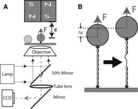
(A) Schematic representation of the magnetic-tweezers setup. The protein is tethered between a paramagnetic bead and the coverslip surface. Force is applied to the bead by a pair of permanent magnets above the sample, and changing the distance, d, between the magnets and the bead controls the magnitude of the force. Beads are illuminated by light through the objective and imaged by charge-coupled device. A bead stuck on the surface is used as a reference to eliminate drift in three dimensions. (B) Schematic representation of the unfolding of a domain in the tethered protein. Domain unfolding leads to an abrupt increase in the height of the bead, Δz. The resulting change in the bead diffraction pattern is used to measure Δz at a resolution of ∼2 nm.
In the experiments, the His-tag on the N-terminal end of the protein was attached to a nitriloacetic acid (NTA)-nickel- or NTA-copper-coated coverslip surface (14), and the biotinylated Avi-tag on the C-terminus was attached to a 2.8-μm-diameter streptavidin-coated paramagnetic bead (Dynal M-280 bead, Invitrogen, Carlsbad, CA). The paramagnetic bead is used not only to apply force to the tethered protein, but also as a reporter of the extension changes of the protein under tension (see Sample preparation in the Supporting Material). When a domain in the tethered protein is unfolded, the extension will display a stepwise increase (see Fig. 2 B). Our magnetic-tweezers setup has a spatial resolution of ∼2 nm and a temporal resolution of ∼10 ms (13).
Adjusting the distance, d, between the permanent magnets and the sample can control the force, F(d) (Fig. 2 A). Working under the force-clamp mode, d was fixed and a constant force was applied. In this mode, the tether was held for 30 s at each force. The three-dimensional bead fluctuation is recorded under each force step. Because the protein tethers are very short, this fluctuation cannot be directly used to calculate forces >10 pN (13). Forces >10 pN can be calibrated using a calibration curve, F(d), obtained from long λ-DNA with contour length ∼16 μm (13). Due to the heterogeneity of the Dynal M-280 bead, at a given d, the force can vary with a standard deviation of ∼20%. After eliminating the heterogeneity at forces <10 pN, where the force can be directly calculated by bead fluctuation, the relative error in force calibration is ∼5% using the method described in Chen et al. (13). The accuracy of force measurement was confirmed previously by overstretching of short DNA (15).
Loading rate control is also implemented in experiments. In the loading rate control experiments, the magnets are moved according to a programmed trajectory, d(t), which was designed such that force F(t) is a linear function. In this constant-loading-rate working mode, we cannot calculate the force applied to individual beads, since the force is varying with time. Instead, we calibrate force based on the averaged F(d) (13). As a result, both loading rate and unfolding force estimated in the constant-loading-rate experiments have a relative error of ∼20% for each individual measurement. Our conclusion is based on statistical analysis from >10 tethers in all experiments.
The force-clamp working mode and loading-rate control can also be done using AFM with feedback control (16). Compared with AFM, magnetic tweezers have worse spatial and temporal resolution, but they have the advantages of ultrastable force and long-term three-dimensional bead tracking without drift.
Results
Mechanical stability of the rod 1 domains
As mentioned in the Introduction, the rod 1 domains of FLNa include IgFLNa 1–15, in which the domains are linearly arranged. These domains can be further divided into two segments, IgFLNa 1–8, which barely interacts with F-actin, and IgFLNa 9–15, which increases affinity to F-actin by one order of magnitude (6). The functional difference between these two segments may cause difference in their mechanical stability. Therefore, we investigate their stability separately. To have an equal number of domains for comparison, we have used IgFLNa 8–15 instead of IgFLNa 9–15 in experiments.
We begin with the studies of IgFLNa 1–8 where the tethers are stretched by a force of 2∼170 pN. Fig. 3 A shows two representative processes of stretching IgFLNa 1–8 tethers at a constant loading rate 1.6 ± 0.3 pN/s (see Magnetic tweezers in the Supporting Material). A gradual increase in extension, which indicates the elastic response of intact IgFLNa 1–8, was observed till the force reached ∼50 pN.
Figure 3.
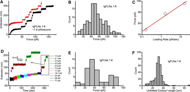
(A) Two representative unfolding processes of IgFLNa 1–8 under a fixed loading rate of ∼1.6 pN/s. An extension offset of 100 nm is applied to the upper curve. (B) Histogram of the unfolding forces of IgFLNa 1–8 under a constant loading rate of ∼1.6 pN/s. The distribution peak is at ∼70 pN. (C) Peak unfolding forces for IgFLNa 1–8 under three different loading rates. The solid line is a linear fit of the three experimental data points. (D) Representative time course of the unfolding process of IgFLNa 1–8 under constant forces indicated by the different colors. At each force, the tether was held for 30 s. (E) Histogram of the unfolding forces of IgFLNa 1–8 from 52 unfolding events obtained according to the procedure in D. (F) Histogram of the unfolded contour length of IgFLNa 1–8.
Domain unfolding started at ∼50 pN, as indicated by a stepwise extension increase of ∼25 nm. More unfolding events were observed at higher forces till the tether broke. In these two representative unfolding processes, one tether has all the eight domains unfolded before tether breaking, whereas the other has seven domains unfolded before tether breaking. In most experiments, less than eight unfolding events could be recorded before tether breaking. The tether breaking occurs at either the His-tag end or the biotin end, since these are the only noncovalent linkages in the tether. Although the force of dissociation of His-tag from the Ni/Cu-NTA surface has not been reported, it is likely the weakest link, since the dissociation constant of His-tag from the Ni/Cu-NTA surface is much lower than that of biotin-streptavidin (18). Therefore, we believe that it may contribute the most to tether breaking in our experiments.
To quantify the mechanical stability of IgFLNa 1–8, we collected 107 unfolding events from 20 tethers under the same loading rate, 1.6 ± 0.3 pN/s, and plotted the histograms of the unfolding forces in Fig. 3 B. It can be seen that the unfolding forces of IgFLNa 1–8 are distributed in a wide range, with a peak at ∼70 pN. To estimate the energy barrier that unfolding of domains needs to overcome, we plotted the peak force as a function of three loading rates: 0.16 ± 0.03 pN/s, 1.6 ± 0.3 pN/s, and 16 ± 3 pN/s (see Distributions of unfolding forces of IgFLNa 1–8 under different loading rates in the Supporting Material). We do not have loading-rate dependence over a wider range due to instrument limitation. As expected, the force depends linearly on the loading rate in the logarithm scale (19): , where is the peak of the unfolding force, kB is Boltzmann's constant, T is the absolute temperature, r is the loading rate, is the distance between the native state and the transition state along the force direction, and is the unfolding rate of protein domain at zero force. From the fitting, was estimated to be 0.40 ± 0.06 nm, and s−1. For comparison, nm and s−1 for titin I27 in previous AFM experiments using tandem I27 domains (20). Here, we want to emphasize that the domains in IgFLNa 1–8 are heterogeneous in amino acid sequence and molecular weight; therefore, these results should be considered as average over all the domains. Due to many uncertain factors from domain heterogeneity, we have refrained from studying the loading-rate dependence for other segments. In the rest of the experiments, the loading rate was fixed at 1.6 ± 0.3 pN/s, since under this loading rate, the time required to build up ∼10 pN is close to the timescale observed in the protrusion-retraction cycle of cells (11).
Compared with AFM, magnetic tweezers have a unique advantage in stable force-clamp mode over long time. This allows studies of unfolding dynamics under constant forces. Fig. 3 D shows a representative unfolding time course of IgFLNa 1–8 under a series of constant forces. At each force, the tether was kept for 30 s. Then, the magnets were moved 0.5 mm closer to the bead to apply a bigger force. Therefore, the force increases stepwise and nearly exponentially, since F(d) is nearly an exponential function (13). In the figure, the time course recorded at a particular constant force is indicated by a unique color. Unfolding started at ∼38 pN, where two unfolding events were observed. At a larger force, ∼71 pN, three more unfolding events were recorded before the tether broke.
Similar to the unfolding experiment under constant loading rate, we quantify the mechanical stability of IgFLNa 1–8 by making a histogram of the unfolding force over 52 unfolding events. Fig. 3 E shows that the unfolding forces are distributed in a wide range, with a peak at ∼35 pN, smaller than the ∼70-pN peak force observed under the loading rate of 1.6 ± 0.3 pN/s. This is not surprising, since the experimental timescale is longer in the force-clamp experiment than in the experiments with ∼1.6 pN/s constant loading rate.
In both the constant-loading-rate and force-clamp-mode experiments, the unfolding events are characterized by a stepwise increase in extension. Assuming that an unfolding event results in conversion of a folded structure into an extended peptide chain, the released contour length can be estimated using the wormlike chain (WLC) with a persistence length of 0.5 nm (21,22). Fig. 3 F shows histograms of the unfolded contour length based on 360 unfolding events obtained from both constant-loading-rate and constant-force experiments. A peak of ∼31 nm is observed, consistent with previous AFM data showing a peak of 31 nm for FLNa Ig domains, which have an average of ∼96 amino acids/domain (10), and a peak of ∼29 nm for titin I27, which has 89 amino acids (23,24).
Having analyzed the mechanical stability of IgFLNa 1–8, we proceeded to study IgFLNa 8–15, which contains the secondary actin-binding sites under a constant loading rate of 1.6 ± 0.3 pN/s. Fig. 4 A shows two representative unfolding processes of IgFLNa 8–15, of which one curve shows eight unfolding events before tether breaking. Fig. 4 B shows the peak of the unfolding force shifting to a smaller force of ∼40 pN. This is not surprising, since IgFLNa 8–15 contains the secondary actin binding sites, whereas IgFLNa 1–8 does not. Compared with Fig. 3 F, the histogram of the unfolded contour length for IgFLNa 8–15 (Fig. 4 C) did not appear to be different from that for IgFLNa 1–8, except that there seem to be slightly more unfolding events, with a shorter unfolded contour length of ∼15 nm observed for IgFLNa 8–15.
Figure 4.
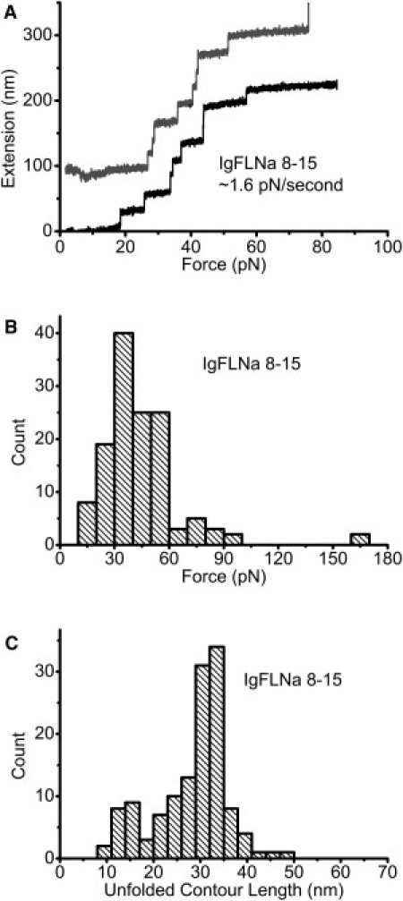
(A) Two representative unfolding processes of IgFLNa 8–15 under a loading rate of ∼1.6 pN/s. An extension offset of 100 nm is applied to the upper curve. (B) Histogram of unfolding forces of IgFLNa 8–15 under the same loading rate as in A. (C) Histogram of the unfolded contour length of IgFLNa 8–15.
Mechanical stability of the rod 2 domains
Comparing with the linearly arranged rod 1 domains, rod 2 domains (IgFLNa 16–23) are arranged very differently. A remarkable feature of IgFLNa 16–23 is that it is a compact structure due to interdomain interaction (6,7). In addition, IgFLNa 16–23 is also functionally distinct from the rod 1 domains. It provides binding sites for numerous proteins of great functional diversity (3,9). It has been suggested that interdomain interactions in IgFLNa 16–23 and its binding proteins are regulated by mechanical force (8,9). As such, IgFLNa 16–23 is also considered to play critical roles in mechanosensing of FLNa. The unique domain organization of IgFLNa 16–23 and its possible relevance to the mechanosensing functions of FLNa make it important to investigate its force response, which has remained unclear to date.
Fig. 5 A shows two representative unfolding processes of IgFLNa 16–23 under a constant loading rate of 1.6 ± 0.3 pN/s. Unfolding events were observed at <20 pN. The histogram of the unfolding force (Fig. 5 B) shows that the force peak shifts to 10–20 pN, significantly lower than the unfolding force peaks of ∼70 pN and ∼40 pN observed for IgFLNa 1–8 (Fig. 3 B) and IgFLNa 8–15 (Fig. 4 B), respectively. A similar trend was observed in the constant-force experiments. In the representative time course of the constant-force experiment (Fig. 5 C), unfolding was observed at a small force of ∼7 pN. Consistent with this, the histogram of unfolding force shows a peak at <10 pN (Fig. 5 D). In fact, a significant fraction of unfolding events (∼40%) occurred under a force of <10 pN. These results clearly demonstrate that IgFLNa 16–23 is much less mechanically stable than the rod 1 domains. Our results suggest that unfolding of some domains inside IgFLNa 16–23 are possible in vivo, since the unfolding force of ∼10 pN is close to the force generated by one or a few myosin motors (12).
Figure 5.
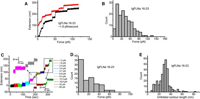
(A) Two representative unfolding processes of IgFLNa 16–23 under a fixed loading rate of ∼1.6 pN/s. An extension offset of 100 nm is applied to the upper curve. (B) Histogram of the unfolding forces of IgFLNa 16–23 under the same loading rate as in A. (C) Representative time course of the unfolding processes of IgFLNa 16–23 in force-clamp measurements in which different forces are indicated by different colors. At each force, the tether was held for 30 s. (D) Histogram of the unfolding forces of IgFLNa 16–23 in force-clamp measurements from 86 unfolding events obtained according to the procedure in C. (E) Histogram of the unfolded contour length of IgFLNa 16–23.
To see whether there is a difference in the unfolded contour length, we plotted the histogram of the unfolded contour length (Fig. 5 E), which shows that the peak is still located at ∼31 nm, similar to the peaks observed in IgFLNa 1–8 and IgFLNa 8–15. However, the fraction of small steps seems larger in IgFLNa 16–23. From the data we have collected, the fraction of unfolding events that released <20-nm contour lengths was 11% for IgFLNa 1–8, 17% for IgFLNa 8–15, and 19% for IgFLNa 16–23, which is similar to that for IgFLNa 8–15. A possible explanation for the smaller unfolding lengths in IgFLNa 8–15 and IgFLNa 16–23 is that they are less stable than IgFLNa 1–8. It can be intuited that a less stable domain is more likely to have partially unfolded intermediate structures at low loading rates.
Discussion
Our experiments have revealed differential mechanical stabilities of the three FLNa segments: IgFLNa 1–8, IgFLNa 8–15, and IgFLNa 16–23. The rod 2 segment, IgFLNa 16–23, has a distinct distribution of the unfolding forces from IgFLNa 1–8 and IgFLNa 8–15 in the rod 1 segment. A significantly large percentage of unfolding events for IgFLNa 16–23 occurred at a lower force range compared with IgFLNa 1–8 and IgFLNa 8–15. To see more details of the unfolding events at low force, we replotted the histograms of unfolding force using the data from Figs. 3 B, 4 B, and 5 B in logarithm scale for all three segments under the same loading rate of 1.6 ± 0.3 pN/s. Fig. 6 shows that in logarithm scale, the unfolding forces of IgFLNa 1–8 and IgFLNa 8–15 still show single-peak distribution. However, a unique two-peak distribution was revealed for IgFLNa 16–23. One peak is located at ∼12 pN, whereas the other occurs at ∼40 pN. The force peak at 12 pN is interesting, because it is rarely observed in either IgFLNa 1–8 or IgFLNa 8–15 and is close to forces generated by myosin motors.
Figure 6.
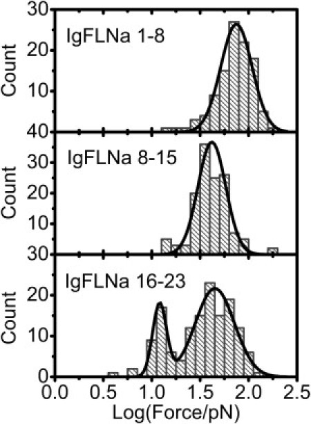
Histograms in logarithm scale of unfolding forces for IgFLNa 1–8 (upper), IgFLNa 8–15 (middle), and IgFLNa 16–23 (lower) at a loading rate of ∼1.6 pN/s. Solid curves are results of Gaussian fitting of the distribution peaks.
The different mechanical stability of these segments must be related to how their Ig domains are organized. An intact IgFLNa domain without pairing interaction with neighboring domains is composed of seven β-strands (A–G) (25). The first strand and last strand have the same orientation, resulting in a shear-force pulling geometry when the force is applied to its two termini (see Stretching geometry in the Supporting Material). In a linear array of such Ig domains, such as IgFLNa 1–8, IgFLNa 8–15, or tandem titin I27 domains (23,24), all the domains will feel the same shear force when the array is stretched. The situation is different in IgFLNa 16–23, where there are domain pairs (7,8). Strands A of IgFLNa 18 and 20 are excluded from their normal positions and interact with the CD faces of neighboring IgFLNa 19 and 21, respectively. When stretched, these interfaces will feel an unzipping force; therefore, these interfaces should be unzipped at lower forces (9). We propose that the unfolding at smaller forces centered on ∼12 pN is likely related to the dissociation of these domain pairs in IgFLNa 16–23.
The presence of the second peak of unfolding force in IgFLNa 16–23, at ∼40 pN, can also be understood in terms of the domain organization. After unzipping of an interface in a domain pair, the two dissociated domains may be subject to different force geometry. For example, right after the A-strand of IgFLNa 20 is unzipped from IgFLNa 21, IgFLNa 20 is still under the unzipping-force geometry. In contrast, the domain 21 will be in shear-force geometry (9) and can withstand a higher force. Such domains (IgFLNa 17, 19, 21, 22, and 23) should have force responses similar to those in the rod 1 segment. This may explain why the second peak at higher unfolding force exists in IgFLNa 16–23.
According to the simulation results in Pentikäinen and Ylänne (9), a few different intermediate states may exist during domain-pair dissociation of IgFLNa 20-21 and IgFLNa 18-19, corresponding to different unfolding steps. In our experiments, we cannot differentiate between domain unfolding and domain-pair dissociation. However, such signals should lead to a broader distribution of the nominal unfolded contour length converted from the unfolding-step size according to the WLC polymer model. This is in general agreement with our observation of a greater number of smaller unfolded contour lengths in IgFLNa 16–23 (Fig. 5 E) compared with that in IgFLNa 1–8 (Fig. 3 F). Here, we should note that IgFLNa 8–15 also had a significant fraction of unfolding events with smaller released contour length (Fig. 4 C). However, this does not conflict with our argument, since IgFLNa 8–15 is also less stable than IgFLNa 1–8.
The mechanical stability of the entire IgFLNa 1–24 had been investigated using AFM at a pulling rate of 0.37 μm/s. Three distinct peaks of unfolding forces were reported at ∼85 pN, ∼135 pN, and ∼185 pN (10). This is consistent with observations in our experiments of three peaks, located at ∼12 pN (IgFLNa 16–23), ∼40 pN (IgFLNa 8–15 and IgFLNa 16–23), and ∼70 pN (IgFLNa 1–8), obtained under a loading rate of ∼1.6 pN/s. The peak forces in our experiments are shifted to a lower force range than those observed in AFM experiments, which can be understood by the difference in the loading rates between the AFM experiments and our magnetic-tweezers experiments. From the pulling rate of 0.37 μm/s in the AFM experiment, the loading rate upon unfolding of FLNa domains is ∼2000 pN/s, three orders of magnitude faster than our constant loading rate of ∼1.6 pN/s (see Loading rate estimate in AFM experiment in the Supporting Material). The AFM experiments also report a peak of ∼31 nm in the distribution of the unfolded contour length. A histogram based on all data obtained from IgFLNa 1–8, 8–15, and 16–23 has shown a similar peak around ∼31 nm but with a larger portion of small unfolded contour lengths ∼15 nm (see Overall distribution of unfolded contour length in the Supporting Material). This difference is likely because more intermediate unfolding states were observed in our magnetic-tweezers experiments, with a much lower loading rate than that used in the AFM experiments.
Our finding that the rod 1 and rod 2 segments have different mechanical stability has important implications for the functions of FLNa. The stable rod 1 segment is compatible with the function of supporting the tension of the actin network, whereas the less stable rod 2 region is consistent with the function of mechanosensing. For example, it is known that the CD face of domain 21 is the binding site of the β-integrin tail (26). However, this binding is inhibited unless the A-strand of domain 20 dissociates from the domain 21 (8). Our results suggest that the dissociation of a domain pair in IgFLNa 16–23 can occur under a force of ∼10 pN or less, which is close to the force range that can be generated by several myosin motors (12). Taken together, these results suggest that a force-regulated FLNa-integrin interaction by multiple myosin motors is possible in vivo (27).
Acknowledgments
The work performed at Singapore was supported by the Mechanobiology Institute, Singapore. Work at Harvard was supported by the Harvard University Science and Engineering Committee Seed Fund for Interdisciplinary Science.
Supporting Material
References
- 1.Kasza K.E., Nakamura F., Weitz D.A. Filamin A is essential for active cell stiffening but not passive stiffening under external force. Biophys. J. 2009;96:4326–4335. doi: 10.1016/j.bpj.2009.02.035. [DOI] [PMC free article] [PubMed] [Google Scholar]
- 2.Stossel T.P., Condeelis J., Shapiro S.S. Filamins as integrators of cell mechanics and signalling. Nat. Rev. Mol. Cell Biol. 2001;2:138–145. doi: 10.1038/35052082. [DOI] [PubMed] [Google Scholar]
- 3.Nakamura F., Stossel T.P., Hartwig J.H. The filamins: organizers of cell structure and function. Cell Adh. Migr. 2011;5:160–169. doi: 10.4161/cam.5.2.14401. [DOI] [PMC free article] [PubMed] [Google Scholar]
- 4.Tseng Y., An K.M., Wirtz D. The bimodal role of filamin in controlling the architecture and mechanics of F-actin networks. J. Biol. Chem. 2004;279:1819–1826. doi: 10.1074/jbc.M306090200. [DOI] [PubMed] [Google Scholar]
- 5.Zhou A.X., Hartwig J.H., Akyürek L.M. Filamins in cell signaling, transcription and organ development. Trends Cell Biol. 2010;20:113–123. doi: 10.1016/j.tcb.2009.12.001. [DOI] [PubMed] [Google Scholar]
- 6.Nakamura F., Osborn T.M., Stossel T.P. Structural basis of filamin A functions. J. Cell Biol. 2007;179:1011–1025. doi: 10.1083/jcb.200707073. [DOI] [PMC free article] [PubMed] [Google Scholar]
- 7.Heikkinen O.K., Ruskamo S., Ylänne J. Atomic structures of two novel immunoglobulin-like domain pairs in the actin cross-linking protein filamin. J. Biol. Chem. 2009;284:25450–25458. doi: 10.1074/jbc.M109.019661. [DOI] [PMC free article] [PubMed] [Google Scholar]
- 8.Lad Y., Kiema T., Ylänne J. Structure of three tandem filamin domains reveals auto-inhibition of ligand binding. EMBO J. 2007;26:3993–4004. doi: 10.1038/sj.emboj.7601827. [DOI] [PMC free article] [PubMed] [Google Scholar]
- 9.Pentikäinen U., Ylänne J. The regulation mechanism for the auto-inhibition of binding of human filamin A to integrin. J. Mol. Biol. 2009;393:644–657. doi: 10.1016/j.jmb.2009.08.035. [DOI] [PubMed] [Google Scholar]
- 10.Furuike S., Ito T., Yamazaki M. Mechanical unfolding of single filamin A (ABP-280) molecules detected by atomic force microscopy. FEBS Lett. 2001;498:72–75. doi: 10.1016/s0014-5793(01)02497-8. [DOI] [PubMed] [Google Scholar]
- 11.Giannone G., Dubin-Thaler B.J., Sheetz M.P. Periodic lamellipodial contractions correlate with rearward actin waves. Cell. 2004;116:431–443. doi: 10.1016/s0092-8674(04)00058-3. [DOI] [PubMed] [Google Scholar]
- 12.Finer J.T., Simmons R.M., Spudich J.A. Single myosin molecule mechanics: piconewton forces and nanometre steps. Nature. 1994;368:113–119. doi: 10.1038/368113a0. [DOI] [PubMed] [Google Scholar]
- 13.Chen H., Fu H., Yan J. Improved high-force magnetic tweezers for stretching and refolding of proteins and short DNA. Biophys. J. 2011;100:517–523. doi: 10.1016/j.bpj.2010.12.3700. [DOI] [PMC free article] [PubMed] [Google Scholar]
- 14.del Rio A., Perez-Jimenez R., Sheetz M.P. Stretching single talin rod molecules activates vinculin binding. Science. 2009;323:638–641. doi: 10.1126/science.1162912. [DOI] [PMC free article] [PubMed] [Google Scholar]
- 15.Fu H., Chen H., Yan J. Transition dynamics and selection of the distinct S-DNA and strand unpeeling modes of double helix overstretching. Nucleic Acids Res. 2011;39:3473–3481. doi: 10.1093/nar/gkq1278. [DOI] [PMC free article] [PubMed] [Google Scholar]
- 16.Schlierf M., Li H., Fernandez J.M. The unfolding kinetics of ubiquitin captured with single-molecule force-clamp techniques. Proc. Natl. Acad. Sci. USA. 2004;101:7299–7304. doi: 10.1073/pnas.0400033101. [DOI] [PMC free article] [PubMed] [Google Scholar]
- 17.Reference deleted in proof.
- 18.Knecht S., Ricklin D., Ernst B. Oligohis-tags: mechanisms of binding to Ni2+-NTA surfaces. J. Mol. Recognit. 2009;22:270–279. doi: 10.1002/jmr.941. [DOI] [PubMed] [Google Scholar]
- 19.Anderson K.L., Radford S.E., Brockwell D.J. The dynamical response of proteins under force. In: Noy A., editor. Handbook of Molecular Force Spectroscopy. Springer; New York: 2008. pp. 205–249. [Google Scholar]
- 20.Carrion-Vazquez M., Oberhauser A.F., Fernandez J.M. Mechanical and chemical unfolding of a single protein: a comparison. Proc. Natl. Acad. Sci. USA. 1999;96:3694–3699. doi: 10.1073/pnas.96.7.3694. [DOI] [PMC free article] [PubMed] [Google Scholar]
- 21.Bustamante C., Marko J.F., Smith S. Entropic elasticity of λ-phage DNA. Science. 1994;265:1599–1600. doi: 10.1126/science.8079175. [DOI] [PubMed] [Google Scholar]
- 22.Junker J.P., Ziegler F., Rief M. Ligand-dependent equilibrium fluctuations of single calmodulin molecules. Science. 2009;323:633–637. doi: 10.1126/science.1166191. [DOI] [PubMed] [Google Scholar]
- 23.Carrion-Vazquez M., Marszalek P.E., Fernandez J.M. Atomic force microscopy captures length phenotypes in single proteins. Proc. Natl. Acad. Sci. USA. 1999;96:11288–11292. doi: 10.1073/pnas.96.20.11288. [DOI] [PMC free article] [PubMed] [Google Scholar]
- 24.Harris N.C., Song Y., Kiang C.H. Experimental free energy surface reconstruction from single-molecule force spectroscopy using Jarzynski's equality. Phys. Rev. Lett. 2007;99:068101. doi: 10.1103/PhysRevLett.99.068101. [DOI] [PMC free article] [PubMed] [Google Scholar]
- 25.Nakamura F., Pudas R., Ylänne J. The structure of the GPIb-filamin A complex. Blood. 2006;107:1925–1932. doi: 10.1182/blood-2005-10-3964. [DOI] [PMC free article] [PubMed] [Google Scholar]
- 26.Kiema T., Lad Y., Calderwood D.A. The molecular basis of filamin binding to integrins and competition with talin. Mol. Cell. 2006;21:337–347. doi: 10.1016/j.molcel.2006.01.011. [DOI] [PubMed] [Google Scholar]
- 27.Koenderink G.H., Dogic Z., Weitz D.A. An active biopolymer network controlled by molecular motors. Proc. Natl. Acad. Sci. USA. 2009;106:15192–15197. doi: 10.1073/pnas.0903974106. [DOI] [PMC free article] [PubMed] [Google Scholar]
Associated Data
This section collects any data citations, data availability statements, or supplementary materials included in this article.