Abstract
Recently, a novel linearized constitutive model with a new strain measure that absorbs the material nonlinearity was validated for arteries. In this study, the linearized arterial stress-strain relationship is implemented into a finite element method package ANSYS, via the user subroutine USERMAT. The reference configuration is chosen to be the closed cylindrical tube (no-load state) rather than the open sector (zero-stress state). The residual strain is taken into account by analytic calculation and the incompressibility condition is enforced with Lagrange penalty method. Axisymmetric finite element analyses are conducted to demonstrate potential applications of this approach in a complex boundary value problem where angioplasty balloon interacts with the vessel wall. The model predictions of transmural circumferential and compressive radial stress distributions were also validated against an exponential-type Fung model, and the mean error was found to be within 6%.
Keywords: Blood vessel, residual strain, incompressibility, user subroutine
1 Introduction
The Finite Element Method (FEM) has been extensively used to analyze the mechanics of blood vessels [1–11]. There are still some practical issues, however, that need further investigations. For instance, shell theory [1, 4] is not sufficient for thick-walled vessels, and isotropic models [2, 3, 7, 8, 10] are first-order approximation that do not reflect the anisotropy of vascular tissue. Gasser et al. [5] and Holzapfel et al. [6] implemented a microstructure-motivated constitutive model, but their geometric model of vessel selects the zero-stress state as the reference configuration which is not always convenient. Zhang et al. [9] incorporated the Fung model into ANSYS, but their analysis was limited to small shear deformation. Liu et al. [11] analyzed the effects of myocardial constraint, but their code did not extend to complex loadings; e.g., contact between a device and vessel wall.
Among the biomedical FEM applications, several groups have analyzed balloon angioplasty to understand the interaction between the balloon and the stent [22–25]. Oh et al. [22] simulated the response of atherosclerotic arteries to balloon angioplasty, where the arteries were described by an isotropic material model. Gourisankaran and Sharma [23] also used an isotropic model and investigated the stresses in the arterial wall and atherosclerotic plaque of diseased arteries induced by balloon dilatation. Holzapfel et al. [24] simulated balloon angioplasty using a layer-specific three-dimensional anisotropic model based on in vitro magnetic resonance imaging of a human stenotic postmortem artery. The FEM analysis of Gasser et al. [25] considered the balloon-induced overstretch of remnant non-diseased tissues in antherosclerotic arteries. The model took into account the multi-layer structure of the artery including media, adventitia, and plaque; residual stresses, and plastic response of the tissue beyond the elastic limit as well.
Here, we implement a linearized anisotropic arterial constitutive relation in a commercial FEM package ANSYS v11.0 (ANSYS, Inc.). The linearized relation has the advantage of having less material parameters than the general anisotropic constitutive relation of Fung’s type which makes it easier to determine the parameters from experimental data. The advantage of commercial FEM package is that general boundary value problems having complex contact and fluid-solid interaction are readily solvable. Illustratory examples of balloon (compliant and noncompliant) angioplasty involving compliant and noncompliant balloons are solved and compared based on the proposed platform. We also validate the transmural stress predictions with a Fung type model. The technical feasibility of this approach and the potential applications are envisioned.
2 Methods
2.1 Deformation and Constitutive Model
The mechanical property of blood vessel wall is modeled as being cylindrically orthotropic, elastic and nearly incompressible. The zero-stress state (ZSS, described by cylindrical coordinates R, Θ, Z) is a cut-open sector (Fig. 1(a)), and the deformed configuration (described by cylindrical coordinates r, z, θ) is a closed circular tube (Fig. 1(b)). For convenience, the reference configuration is selected as the no-load state where the vessel is intact and subjected to zero blood pressure and no axial stretch. Therefore, there is a residual deformation gradient from ZSS to the reference configuration, as will be given later. At ZSS, the inner and outer circumferences, Li and Lo, and the cross-sectional wall area A0 are measured. The inner and outer radii of the open sector Ri and Ro, and the opening angle Φ are:
| (1) |
Fig. 1.
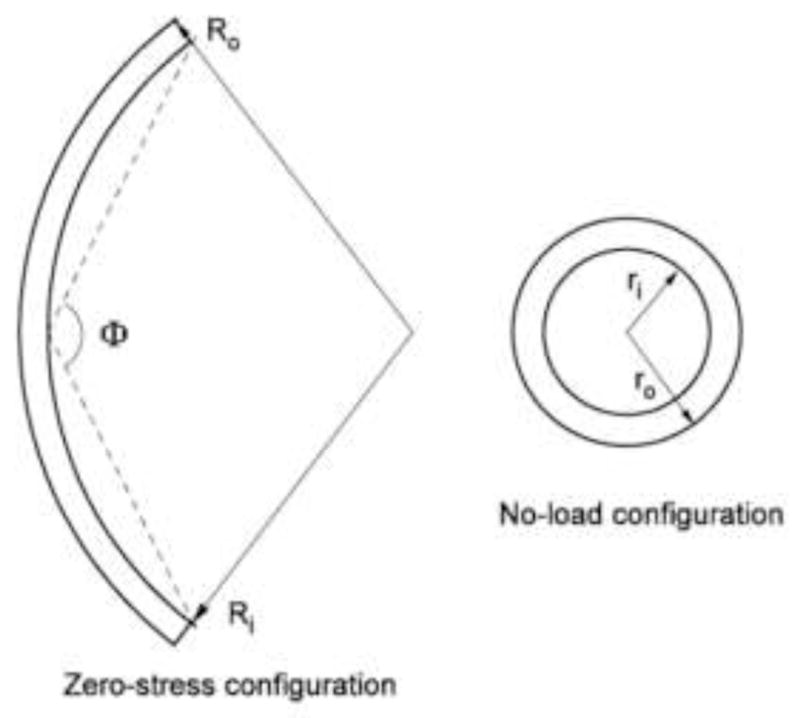
The zero-stress state (a) and deformed state (b) of the arterial vessel. The reference configuration is a deformed state without pressure and axial stretch.
Following the coordinate ordering in ANSYS, we relate the deformed configuration (r, z, thetas;) to the cylindrical reference configuration (ξ, ζ, ψ) by:
| (2) |
Thus the total deformation gradient F (referring to ZSS) is calculated as the tonsorial product of the deformation gradient from the reference configuration to the current deformed configuration, F1, and that from ZSS to the reference configuration, F0, as F = F1 · F0. The matrix form is
| (3) |
where Λr, Λz and Λθ are the principal stretch ratios in the reference radial, axial and circumferential directions, respectively, which can be analytically calculated from the incompressibility condition [9,12], as
| (4) |
in which Λz equals to the prescribed axial stretch, and the relation between the reference and ZSS radial coordinates, r and R, respectively, is
| (5) |
where ri is the inner radius of the no-load reference configuration. A substitution of Eq. (5) into (4) provides F0 expressed analytically in terms of Ri, χ, Λz, ri, and the radial coordinate, r, in the no-load configuration. In ANSYS USERMAT, F0 is calculated and stored at every integration point.
To define strain, F is usually decomposed [13] as:
| (6) |
and the right Cauchy-Green deformation tensor is calculated as:
| (7) |
In the constitutive model of vessel wall used in this analysis, we employ a logarithmic-exponential (log-exp) strain tensor, which is defined to absorb the material nonlinearity [14]:
| (8) |
where n is a nonlinearity parameter, and I1 the first invariant of C:
| (9) |
Correspondingly, a co-rotational Cauchy stress T was introduced [14], as
| (10) |
where H is the negative hydrostatic pressure, and Te is the deviatoric stress due to deformation, and is related to the deviatoric Cauchy stress σe by σe = RT TeR.
In our analyses [14, 15, 17] on the experimental data of coronary arteries in triaxial deformation (axial stretch, inflation and torsion) [26], it was found that the log-exp strain D and the deviatoric co-rotational Cauchy stress Te can be closely fit by a generalized Hooke’s law that D = M: Te, where M is a constant forth-order compliance tensor as for the classical Hooke’s law of linear elastic materials. For blood vessel, M satisfies incompressibility condition, M: I = 0 such that hydrostatic pressure does not induce any deformation. In axisymmetric deformation, as in the present simulation of balloon angioplasty, the generalized Hooke’s law can be expressed in a matrix form, as:
| (11) |
where[M] is the matrix representation of the compliance tensor M. The parameters E1, E2 and E3 can be interpreted as Young’s moduli in reference to the log-exp strains, G23 is the shear modulus, and ν12, ν13 and ν23 are Poison’s ratios. Unlike the general orthotropic materials where the six parameters E’s and ν’s in Eq. (11) are independent, the incompressibility condition M: I = 0 imposes constraints [16, 21]:
| (12) |
In FEM, it is convenient to calculate stress from strain; i.e., Te = M−1: D = Cα:D. However, the compliance tensor M (or matrix[M]) is singular because of the constraints given by Eq. (12). It is suggested that a regularized inverse is used for numerical simulations [16]; namely, the stiffness matrix [Cα] is computed by:
| (13) |
where [M]−1 is the generalized inverse of [M] [16], and α is a real constant.
ANSYS uses Cauchy stress σ and logarithmic strain ln U. In USERMAT, user must provide the material Jacobian matrix ∂σ/∂ ln U which will be used to calculate the tangent stiffness matrix for Newton-Raphson iterations. For completeness, we present an estimated symmetric Jacobian matrix in the Appendix. In this work, Lagrange penalty method is adopted to enforce the incompressibility condition. To be consistent with [9, 11], we select H = 2ηJ(J−1) where J is the determinant of the total deformation gradient, i.e., J = det(F), and η is the penalty parameter.
2.2 Examples: Stress Analysis on Balloon Angioplasty
We simulated two cases where the left anterior descending (LAD) artery was distended by a compliant and a noncompliant (noncompliant) balloon to simulate the pre-dilatation and post-dilatation processes, respectively, of stent implantation procedures. In both cases, an artery segment undergoes a combined inflation-distension deformation by physiological transmural blood pressure and axial stretch followed by further distension by a balloon. The geometries of the artery in the two models were identical. Specifically, the artery segment was 30 mm long, and a 10 mm long balloon was placed in the middle portion of the vessel lumen. The cross-sectional geometry and material parameters are described below.
We adopted the geometric and material parameters of a porcine left anterior descending (LAD) coronary artery. The inner (Li) and outer (Lo) circumferences of ZSS were Li = 9.81 mm, Lo = 11.18 mm, and the un-stretched cross-sectional area was A0 = 7.97 mm2. The material parameters were n = 1.59, E1 = 18.98 kPa, E2 = 28.31 kPa, E3 = 8.06 kPa [15]. We chose α = 0.01 kPa−1, then Eq. (13) yielded C11 = 43.76, C22 = 47.53, C33 = 28.28, C12 = 5.27, C13 = 24.52, C23 = 20.76, all with units kPa. The shear modulus C44 = 7.66 kPa was set for modeling purpose, based on the estimated parameter C66 = 3.83 kPa in the θ - z plane of the arteries [17]. The penalty parameter η = 50000 kPa is used to enforce incompressibility. The dimensions of the reference configuration of the vessel (in the no-load state) were ri = 1.325 mm and ro = 2.071 mm.
Figure 2(a) and 5 (a) illustrate the model geometries of the two cases, respectively. Due to the symmetry of the geometry and boundary conditions, axisymmetric simulations were conducted to reduce the computational cost. Furthermore, only half of the vessel wall was analyzed due to the symmetry about the middle plane (z = 0). Accordingly, symmetric boundary conditions were applied; i.e., the bottom edge of the arterial wall was allowed to move only in the radial direction, and the left edge (the inner wall) was allowed to move only in the axial direction. In the following, the particular model geometries and pressure boundary conditions for the two cases are given.
Fig. 2.
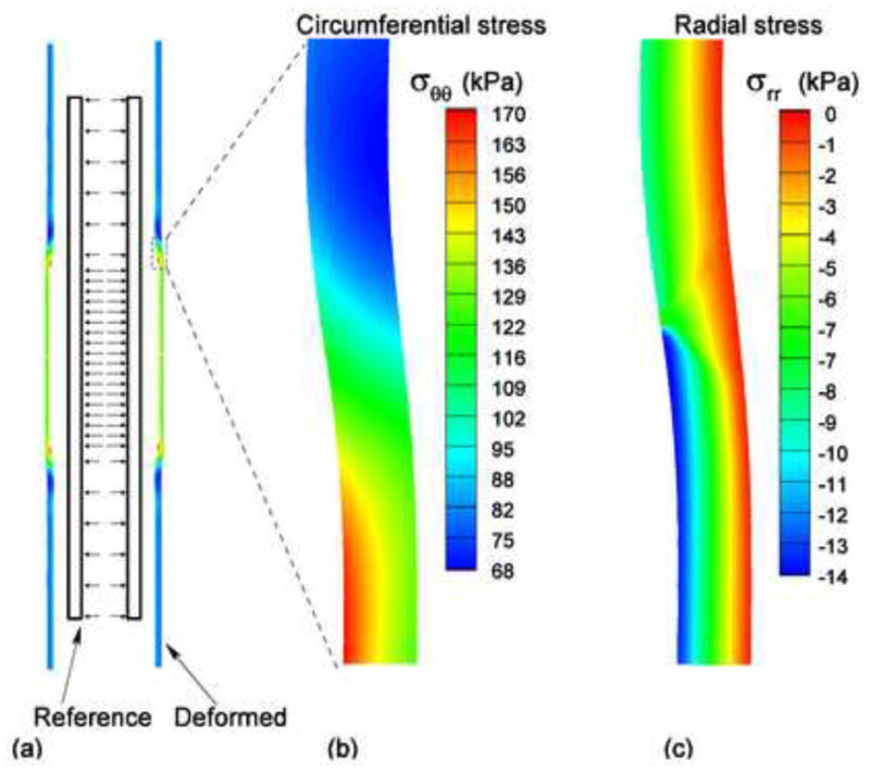
(a) The reference (no-load) and deformed states of the artery expanded by the compliant balloon; (b) The distribution of the circumferential stress near the contact region; (c) The distribution of the radial stress near the contact region.
Fig. 5.
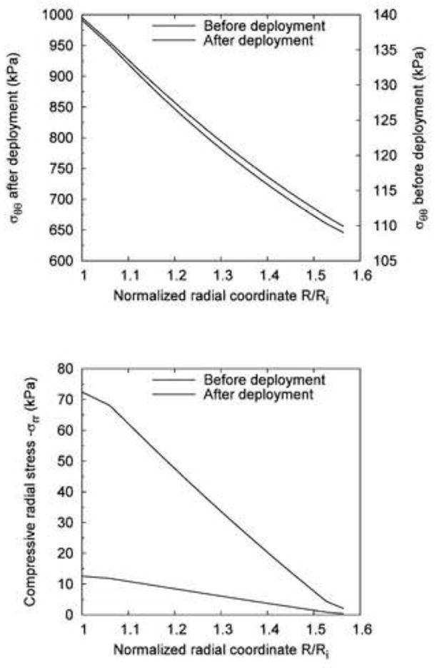
Comparison of the stress distribution across the vessel wall before and after the deployment of the noncompliant balloon (expansion extent: 20%): (a) Circumferential stress σθθ; (b) Compressive radial stress −σrr.
2.2.1 Compliant balloon
This case simulates a pre-dilatation balloon for angioplasty. The material property of the complaint balloon is much more compliant than that of the arterial wall so that the shape of the balloon conforms to that of the vessel lumen after deployment.
Half of the undeformed vessel wall was discretized into 7200 (12×600) four-node quadrilateral elements (PLANE182); i.e., 12 elements in the radial direction, and 600 elements along the axial direction. Since the material parameters above do not predict perfect equilibrium (due to error with the fitting of experimental data) in the no-load reference configuration without pressure and axial stretch, we first constrained the axial stretch at λz = 1.0 and conducted several iterations to allow the artery to attain equilibrium. Then, we stretched the artery to the physiological axial stretch ratio, λz = 1.2. Consequently, the transmural blood pressure pi was increased from 0 to 16.0 kPa (120 mmHg) in the middle portion where the balloon distends the artery, and to 10.67 kPa (80 mmHg) in the rest of the vessel.
2.2.2 Noncompliant balloon
This case simulates a post-dilatation balloon for stent apposition. Because the material property of the balloon is much stiffer than that of the arterial wall, the deployed shape of the balloon is nearly cylindrical, and the diameter reaches a pre-specified dimension regardless of increase in balloon pressure.
The same mesh of the vessel wall was used. The artery was allowed to attain equilibrium at no-load state, and then stretched axially to λz = 1.2. Then, the transmural blood pressure pi was gradually increased from 0 to 13.3 kPa (100 mmHg) in the entire artery segment. While pi was maintained at 13.3 kPa, a noncompliant balloon was deployed to the vessel, and expanded the wall by additional 20% of its in vivo inner radius (ri = 2.59 mm), i.e., 0.52 mm. The balloon was modeled by an enclosed cylinder, with rounded corners (fillet radius = 0.5 mm) to reduce stress concentration. During expansion of the balloon, there is significant contact between the vessel wall and the balloon. We employed rigid-to-flexible surface-to-surface contact elements. The rigid balloon surface was defined as the target surface (TARGE169), and the inner surface of the vessel was designated as the contact surface (CONTA171).
The effect of the expansion extent by the balloon on the circumferential and radial stresses at the inner and outer radii of the vessel was investigated. The expansion extent ranged from 5% to 30%, at an interval of 5%, of the pressurized current inner radius of the vessel. Therefore, seven deformed configurations were considered including the non-balloon-distended case. Similar to the compliant balloon, the stresses at the intersection between the inner and outer surfaces of the vessel and the middle line (z = 0) were sampled for all seven configurations.
2.2.3 Validation with the exponential Fung model
A validation of the current generalized model was conducted against the exponential Fung model by simulating a combined distension-stretch deformation of the vessel under 80 mmHg of pressure. The stretch ratio along the axial direction was Λz =1.2. The hyperelastic strain energy function of the Fung model under axisymmetric deformation is given by:
| (14) |
where Er, Ez, and Eθ are the Green-Lagrange strain in the radial, axial, and circumferential directions, respectively; C is a material constant of stress-like dimension (force per unit area), and b1,…,b6 are dimensionless material constants. The same experimental data were fit by Eq. (14), and the best-fit material constants were C =5.94 kPa, b1 =1.27, b2 =2.78, b3 =0.62, b4 =0.45, b5 =0.13, b6 =0.13.
3 Results
Figure 2(a) shows the reference configuration (no-load) and the deformed configuration for the case of compliant balloon. Figure 2(b) shows the distribution of the circumferential stress σθθ. The maximum value, , occurred on the inner surface of the vessel. Figure 2(c) shows the distribution of the compressive radial stress −σrr. In the region that was expanded by the balloon, the material was compressed. The maximum compressive radial stress, , occurred on the inner surface of the vessel. Figure 3(a) and (b) illustrate, respectively, the circumferential and compressive radial stress profiles across the vessel wall along the middle line (z = 0) before and after the expansion by the compliant balloon. The circumferential stress increased from 102.7 to 163 kPa (+59%) on the inner surface of the arterial wall, and increased from 86.8 to 120.7 kPa (+39%) on the outer surface. The compressive radial stress increased from 10.1 to 13.6 kPa (+35%) on the inner surface of the arterial wall, and increased from 0.33 to 0.42 kPa (+27%) on the outer surface. The monotonic decrease trend of the circumferential and the compressive radial stresses did not change after the vessel was expanded by the compliant balloon.
Fig. 3.
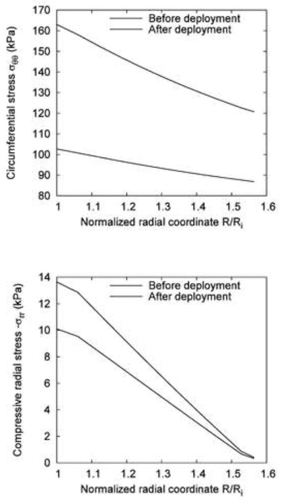
Comparison of the stress distribution across the vessel wall before and after the deployment of the compliant balloon at 120 mmHg: (a) Circumferential stress σθθ; (b) Compressive radial stress −σrr.
Figure 4(a) shows the reference configuration (no-load) and the deformed configuration of the noncompliant balloon case. Figure 4(b) shows the distribution of the circumferential stress. The maximum value, , occurred on the interface between the balloon and the vessel wall. Figure 4(c) shows the distribution of the compressive radial stress, −σrr. At the point where the noncompliant balloon edge contacted with the vessel wall, there was a small region of stress concentration with maximum compressive radial stress, . Figure 5(a) and (b) illustrate respectively the circumferential and compressive radial stress profiles across the vessel wall along the middle line (z = 0) before and after the expansion by the noncompliant balloon. We assumed that the noncompliant balloon was deployed after the pre-dilatation by the compliant balloon (p=100 mmHg). The circumferential stress increased from 140 kPa to 991 kPa (seven times) at the inner surface of the arterial wall, and increased from 110 kPa to 646 kPa (nearly six times) at the outer surface. The compressive radial stress increased from 12.6 to 72.4 kPa (nearly five times) at the inner surface of the arterial wall.
Fig. 4.
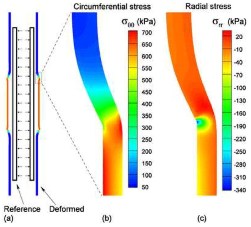
(a) The reference (no-load) and deformed configurations of the vessel expanded by the noncompliant balloon; (b) The distribution of the circumferential stress near the contact region; (c) The distribution of the radial stress near the contact region.
Figure 6(a) and (b) show the effect of the degree of expansion by the noncompliant balloon on the circumferential and radial stresses at the inner and outer radii of the vessel wall. The stresses increased nonlinearly with the increase of balloon diameter. In addition, the circumferential stress at the inner radius increased more drastically than that at the outer radius.
Fig. 6.
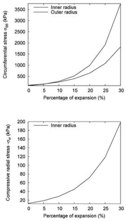
The effect of expansion extent of the noncompliant balloon on the change of wall stresses: (a) Circumferential stress σθθ on the inner and outer surfaces of the vessel; (b) Compressive radial stress −σrr on the inner surface.
Figure 7(a) and (b) show a comparison of circumferential stress and compressive radial stress, respectively, between the current generalized model and the exponential Fung model. The differences between circumferential and radial stress for the two models were well within 5%. At the inner wall, the current generalized model yielded slightly higher stress (+3.2%, 102.7 kPa vs. 99.5 kPa) than the Fung model whereas at the outer wall, it predicted a slightly lower stress (−0.7%, 86.8 kPa vs. 87.4 kPa) than the Fung model. The percent error was bounded within this range across the vessel wall as shown in Figure 7(a). The current model predicted a slightly higher compressive radial stress (mean error of 5.7%, maximum error of 8.9%) across the vessel wall.
Fig. 7.
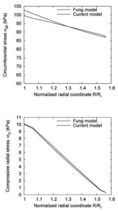
A comparison between the transmural distribution of circumferential (a) and radial (b) stress in the Fung and present model.
4 Discussion
Some authors considered the residual strain by applying appropriate boundary conditions to the stress-free vessel [2, 5, 6, 8]. The use of the no-load state as the reference configuration is more convenient since the zero-stress state is an open sector rather than a cylinder. This issue has been discussed in details by Pena et al [18] and Alastrue et al [19].
The constitutive model in the form of generalized Hooke’s law [14] has been found to fit the experimental data of coronary arteries very well [20]. The linearized stress-strain relation [15] maintains some features of the classic Hooke’s law for small strains; e.g., the trace of strain tensor equals zero when the volume is conserved. Therefore, some useful features such as the number of independent elastic constants and their admissibility for incompressible anisotropic materials [16, 21] hold true. For example, the number of model parameters can be reduced by 3 when incompressibility is considered [15].
In the forward finite element validation of the current model (i.e., the generalized Hooke’s law) against the well-known exponential Fung model, there was < 5% error in the circumferential and radial stresses across the vessel wall between the two models. Such a small error in the prediction of circumferential and radial stresses is not surprising since these two models are distinct; i.e., one is an exponential model, and the other is a linearized one. Although they were fit to the same experimental data, different curve fit quality was achieved due to the linear (current model) or non-linear least squares fit (Fung’s model). Another source of error may be due to the numerical error from the penalty method for incompressibility enforcement. Given these potential sources of error, the comparison between the two models is excellent.
Balloon angioplasty and stenting are well established therapeutic methods of revascularization to restore blood flow in stenotic or occluded arteries. In clinical practices, pre-dilatation is usually performed to open or enlarge the lumen by gradually pressurizing a compliant balloon, and then the stent is deployed by a noncompliant balloon with a predetermined diameter. The compliant pre-dilation balloon can be used to assess the “hardness” of the plaque as well as to size the vessel and lesion. Post-dilatation is often done to ensure good stent apposition against the vessel wall.
The numerical simulations presented in this study demonstrated the capability of the proposed platform in modeling balloon angioplasty, taking into account the contact between the noncompliant balloon and the arterial wall. It is expected that the proposed platform can also be used to simulate more complex situations in balloon angioplasty and stenting, such as interaction between the balloon and the stent, and between the stent and the arterial wall in diseased vessels or geometries. Residual strain and stress were incorporated in the simulation by considering the deformation from the zero-stress open sector to the no-load state. Residual stress plays an important role in homogenizing the transmural circumferential stress across the arterial wall. Therefore, it is important to consider residual strain and stress while modeling balloon angioplasty in order to obtain accurate prediction of the stress distribution in the arterial wall.
The numerical simulation of balloon angioplasty presented in the study has some limitations. Firstly, in order to use analytical method to include residual strain in the finite element model, we assumed that the artery is a cylindrical tube; i.e., making use of the axisymmetry. Secondly, due to the limitation of the direct experimental data, the arterial wall structure was simplified to have only a single layer with uniform constitutive model. The elastic constitutive model is macroscopic and lacks the capability in describing the damage of microstructures in angioplasty. Therefore, the predicted stresses are considered as reference of the onset of potential damage, rather than the actual stresses after damage is initiated.
5 Summary
An axisymmetric model was used to show the feasibility of incorporating an arterial constitutive law into ANSYS when the residual strain was computed analytically and the incompressibility condition was enforced by Lagrange penalty method. This technique may be applied in other commercial codes such as ABAQUS and ADINA which have been used by many investigators [1–4, 8, 19]. The current model can be extended to study biomechanical problems such as fluid-structure interaction [1, 3, 9], stent deployment [4, 7], arterial clamping [5] and many others. A laudable future goal is to implement a fully 3-D arterial model to allow the solution of broader class of problems under physiological and pathophysiological loadings.
Acknowledgments
This research was supported in part by the National Institute of Health-National Heart, Lung, and Blood Institute Grant HL087235.
Appendix
We used a symmetric Jacobian matrix (which is preferred by ANSYS) and computed the tangent stiffness K = ∂(RTσR)/∂ε = ∂(T+HI)/∂lnU as
| (A1) |
where κ = 2ηJ(2J−1). It should be noted that ANSYS exploits engineering strains in USERMAT.
Footnotes
Publisher's Disclaimer: This is a PDF file of an unedited manuscript that has been accepted for publication. As a service to our customers we are providing this early version of the manuscript. The manuscript will undergo copyediting, typesetting, and review of the resulting proof before it is published in its final citable form. Please note that during the production process errors may be discovered which could affect the content, and all legal disclaimers that apply to the journal pertain.
References
- 1.Perktold K, Rappitsch G. Computer-Simulation of Local Blood-Flow and Vessel Mechanics in a Compliant Carotid-Artery Bifurcation Model. J Biomech. 1995;28:845–856. doi: 10.1016/0021-9290(95)95273-8. [DOI] [PubMed] [Google Scholar]
- 2.Delfino A, Stergiopulos N, Moore JE, Meister JJ. Residual Strain Effects on the Stress Field in a Thick Wall Finite Element Model of the Human Carotid Bifurcation. J Biomech. 1997;30:777–786. doi: 10.1016/s0021-9290(97)00025-0. [DOI] [PubMed] [Google Scholar]
- 3.Bathe M, Kamm RD. A Fluid-Structure Interaction Finite Element Analysis of Pulsatile Blood Flow through a Compliant Stenotic Artery. J Biomech Eng. 1999;121:361–369. doi: 10.1115/1.2798332. [DOI] [PubMed] [Google Scholar]
- 4.Berry JL, Manoach E, Mekkaoui C, Rolland PH, Moore JE, Rachev A. Hemodynamics and Wall Mechanics of a Compliance Matching Stent: In Vitro and In Vivo Analysis. J Vasc Interv Radiol. 2002;13:97–105. doi: 10.1016/s1051-0443(07)60015-3. [DOI] [PubMed] [Google Scholar]
- 5.Gasser TC, Schulze-Bauer CAJ, Holzapfel GA. A Three-Dimensional Finite Element Model for Arterial Clamping. J Biomech Eng. 2002;124:355–363. doi: 10.1115/1.1485284. [DOI] [PubMed] [Google Scholar]
- 6.Holzapfel GA, Gasser TC, Stadler M. A Structural Model for the Viscoelastic Behavior of Arterial Walls: Continuum Formulation and Finite Element Analysis. Eur J Mech A-Solids. 2002;21:441–463. [Google Scholar]
- 7.Chua SND, MacDonald BJ, Hashmi MSJ. Finite Element Simulation of Slotted Tube (Stent) With the Presence of Plaque and Artery by Balloon Expansion. J Mater Process Technol. 2004;155–156:1772–1779. [Google Scholar]
- 8.Raghavan ML, Trivedi S, Nagaraj A, McPherson DD, Chandran KB. Three-Dimensional Finite Element Analysis of Residual Stress in Arteries. Ann Biomed Eng. 2004;32:257–263. doi: 10.1023/b:abme.0000012745.05794.32. [DOI] [PubMed] [Google Scholar]
- 9.Zhang W, Herrera C, Atluri SN, Kassab GS. Effect of Surrounding Tissue on Vessel Fluid and Solid Mechanics. J Biomech Eng. 2004;126:760–769. doi: 10.1115/1.1824128. [DOI] [PubMed] [Google Scholar]
- 10.Liang DK, Yang DZ, Qi M, Wang WQ. Finite Element Analysis of the Implantation of a Balloon-Expandable Stent in a Stenosed Artery. Int J Cardiol. 2005;104:314–318. doi: 10.1016/j.ijcard.2004.12.033. [DOI] [PubMed] [Google Scholar]
- 11.Liu Y, Zhang W, Kassab GS. Effects of Myocardial Constraint on the Passive Mechanical Behaviors of the Coronary Vessel Wall. Am J Physiol Heart Circ Physiol. 2008;294:H514–H523. doi: 10.1152/ajpheart.00670.2007. [DOI] [PubMed] [Google Scholar]
- 12.Rachev A, Stergiopulos N, Meister JJ. Theoretical Study of Dynamics of Arterial Wall Remodeling in Response to Changes in Blood Pressure. J Biomech. 1996;29:635–642. doi: 10.1016/0021-9290(95)00108-5. [DOI] [PubMed] [Google Scholar]
- 13.Ogden RW. Non-Linear Elastic Deformations. Halsted Press; New York: 1984. [Google Scholar]
- 14.Zhang W, Wang C, Kassab GS. The Mathematical Formulation of a Generalized Hooke’s Law for Blood Vessels. Biomaterials. 2007;28:3569–3578. doi: 10.1016/j.biomaterials.2007.04.030. [DOI] [PubMed] [Google Scholar]
- 15.Liu Y, Zhang W, Wang C, Kassab GS. A Linearized Constitutive Model for Arteries Considering Incompressibility. J Thero Biol Eng. 2008 In Press. [Google Scholar]
- 16.Loredo A, Klocker H. Generalized Inverse of the Compliance Tensor, and Behaviour of Incompressible Anisotropic Materials - Application to Damage. Mech Res Commun. 1997;24:371–376. [Google Scholar]
- 17.Zhang W, Lu X, Kassab GS. Shear Modulus of Porcine Coronary Artery in Reference to a New Strain Measure. Biomaterials. 2007;28:4733–4738. doi: 10.1016/j.biomaterials.2007.07.025. [DOI] [PubMed] [Google Scholar]
- 18.Pena E, Martinez MA, Calvo B, Doblare M. On the Numerical Treatment of Initial Strains in Biological Soft Tissues. Int J Numer Methods Eng. 2006;68:836–860. [Google Scholar]
- 19.Alastrue V, Pena E, Martinez MA, Doblare M. Assessing the Use of the “Opening Angle Method” To Enforce Residual Stresses in Patient-Specific Arteries. Ann Biomed Eng. 2007;35:1821–1837. doi: 10.1007/s10439-007-9352-4. [DOI] [PubMed] [Google Scholar]
- 20.Wang C, Zhang W, Kassab GS. The Validation of a Generalized Hooke’s Law for Coronary Arteries. Am J Physiol Heart Circul Physiol. 2008;294:H66–H73. doi: 10.1152/ajpheart.00703.2007. [DOI] [PubMed] [Google Scholar]
- 21.Itskov M, Aksel N. Elastic Constants and Their Admissible Values for Incompressible and Slightly Compressible Anisotropic Materials. Acta Mech. 2002;157:81–96. [Google Scholar]
- 22.Oh S, Klelnberger M, McElhaney J. Finite-element analysis of balloon angioplasty. Medical and Biological Engineering and Computing. 1994;32:S108–S114. doi: 10.1007/BF02523336. [DOI] [PubMed] [Google Scholar]
- 23.Gourisankaran V, Sharma MG. The finite element analysis of stresses in atherosclerotic arteries during balloon angioplasty. Critical Reviews in Biomedical Engineering. 2000;28:47–51. doi: 10.1615/critrevbiomedeng.v28.i12.90. [DOI] [PubMed] [Google Scholar]
- 24.Holzapfel GA, Stadler M, Schulze-Bauer CAJ. A Layer-Specific Three-Dimensional model for the simulation of balloon angioplasty using magnetic resonance imaging and mechanical testing. Annals of Biomedical Engineering. 2002;30:753–767. doi: 10.1114/1.1492812. [DOI] [PubMed] [Google Scholar]
- 25.Gasser TC, Holzapfel GA. Finite element modeling of balloon angioplasty by considering overstretch of remnant non-diseased tissues in lesions. Computational Mechanics. 2007;40:47–60. [Google Scholar]
- 26.Lu X, Yang J, Zhao JB, Gregersen H, Kassab GS. Shear Modulus of Porcine Coronary Artery: Contributions of Media and Adventitia. Am J Physiol Heart Circul Physiol. 2003;285:H1966–H1975. doi: 10.1152/ajpheart.00357.2003. [DOI] [PubMed] [Google Scholar]


