Abstract
Adequate stem alignment is essential for the success of Total Hip Arthroplasty (THA) to avoid dislocation and impingement. One factor that has not been sufficiently investigated so far is the stem tilting in the sagittal plane, which has an influence on the position of the centre of the femoral head and thus also on prosthesis torsion. We aimed to evaluate sagittal stem position using 3D-CTs in patients with THA and to develop a mathematical-geometrical model to simulate the functional correlation between sagittal stem tilting and the influence on functional anteversion. Thirty patients with THA underwent a CT-scan. By 3D-reconstruction of the CT-data, femoral-/prosthesis-axis, torsion and sagittal tilt were determined. In accordance with the position of the femoral and prosthesis axes, the rotatory (rAV) (surgically adjusted) and functional (depending on sagittal tilt) anteversion (fAV) was measured. A three dimentional-coordinate transformation was also performed using the Euler-angles to derive a mathematical-geometrical correlation between sagittal stem tilting and corresponding influence on anteversion. The mean rAV was 8° (-11.6 - 26°), the fAV 18° (6.2 - 37°), and the difference 10° (8.8 - 18°). The mean degree of stem tilting was 5.2° (0.7 - 9°) anterior towards the femoral axis. The individually measured parameters are reflected in the mathematical-geometrical model. Depending on the extent of the sagittal deviation, a clear influence on the torsion emerges. For example, a stem implanted at a 15° anteverted angle with a sagittal tilt by two degrees towards anterior results in a fAV of 20°. A clear association between the sagittal stem alignment and the impact on the fAV was demonstrated. Hence, the rotatory anteversion intended by the surgeon may be functionally significantly different. This might pose an increased risk of dislocation or impingement. The sagittal tilt of the prosthesis should therefore be considered in the context of impingement and dislocation diagnosis. In this respect, we recommend a 3D-analysis of stem alignment.
Introduction
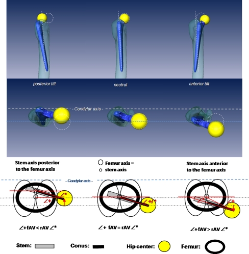
Reconstruction of joint geometry with a return to pain-free, dislocation-safe function and a maximum range of motion is the aim of total hip arthroplasty (THA). A basic prerequisite is exact alignment of stem and cup [1, 3, 7, 11]. The malposition of one or both components can cause dislocation, impingement, wear and aseptic loosening [1–3, 7, 8]. Whereas there are detailed investigations concerning cup positioning, there is little information about prosthesis stem positioning [13]. The stem is implanted in line with the proximal femoral axis, preventing varus/valgus malalignment and taking into consideration an adequate offset, caput collum diaphysis (CCD) angle and stem anteversion [12]. In addition to a stem tilting in the frontal plane (varus/valgus), a stem tilting in the sagittal plane is also possible. To our knowledge, sagittal malalignment is a parameter that has not so far been investigated. In line with theoretical considerations, an anterior or posterior sagittal stem tilt towards the femoral axis influences the position of the centre of the femoral head and thus on the torsion of the prosthetic stem (Fig. 1). If the prosthesis is exactly in line with the proximal femoral axis (no deviation in the sagittal plane), the functional anteversion corresponds to the rotary adjustment by the surgeon. If a stem is tilted forwards in the sagittal plane, meaning the femoral axis and the prosthesis axis deviate from each other, the centre of the femoral head shifts forwards so that the rotational anteversion of the stem will increase functionally. In turn, if the stem is tilted backwards, anteversion will decrease functionally. The degree of torsion desired by the surgeon could therefore deviate functionally depending on the extent of the sagittal tilt and the corresponding shift of the centre of the femoral head. This poses a potential risk factor for luxation or impingement.
Fig. 1.
Correlation between the position of the centre of the femoral head and the prosthesis axis to the proximal femoral axis. Left: Prosthesis axis tilted posterior, the centre of the femoral head shifts backwards, the functional anteversion reduces. Centre: The prosthesis axis corresponds to the proximal femoral axis; functional and rotational anteversion are equal. Right: Prosthesis axis is located in front of the proximal femoral axis (prosthesis is tilted towards anterior); the centre of the femoral head shifts forwards, which increases the functional anteversion. rAV rotatory anteversion (surgically adjusted), fAV functional anteversion (under influence of sagittal tilting)
So far, the mathematical correlation between the tilt in the sagittal plane, the corresponding shift of the centre of the femoral head and the resulting change of the degree of anteversion has not been examined. We thus decided to determine the influence of sagittal stem tilt on functional torsion of the prosthesis and determine a systematic correlation between the two parameters. We first determine joint geometry with prosthesis position via 3D reconstructions of the compute tomography (CT) data sets of patients with primary total hip prostheses. Secondly, we determined a mathematical–geometrical correlation between the sagittal stem tilt in the femur and the corresponding influence on stem anteversion by 3D coordinate transformation in space using Euler angles.
Material and methods
Thirty patients (16 F, 14 M) who had received a total hip implant were included randomly in the study. Written informed content was obtained from all patients. The study was approved by the Ethics Commission (no. EA1/025/07) and the Nuclear Protection Authority (no. 2007-036) and registered in a clinical trial registry (GCTR, registry number: DRKS00000273. Average patient age was 65 years and average body mass index (BMI) 27.2 kg/m2. Exclusion criteria were dysplastic arthrosis greater than Crowe type 1, fractures, previous surgery, presence of a total knee arthroplasty (TKA) or THA on the opposite side, BMI >30 kg/m2 or >80 years of age. A noncemented tapered straight stem was implanted (Alloclassic® SL Stem, Zimmer®, Warsaw, Indiana, US) via a direct lateral or anterolateral approach. The surgery was performed by two surgeons (ST and CP) who had performed more than 1,500 THA each. A stem anteversion of approximately 10° was to be achieved.
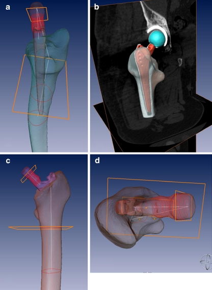
Prior to surgery and seven days after surgery, the patients underwent a quantitative CT (Toshiba®, Toshiba Medical Systems Corporation, Japan). The affected leg was supported in a positioning aid to ensure a standardised neutral position of the leg. Axial scans (matrix 512 × 512 mm, slice thickness:1 mm, slice distance 1 mm) were taken ranging from the anterior superior iliac spine up to the tibial tuberosity and the ipsilateral ankle joint. Afterwards, the CT data set was reconstructed and evaluated with the help of a 3D visualisation software (AMIRA® 5.0, Zuse Institute, Berlin, Germany). The proximal femoral axis, the prosthetic axis, the posterior condylar axis, the pre- and postoperative centre of the femoral head, the tilt of the prosthesis in the sagittal plane and the postoperative rotational and functional anteversion of the prosthesis were determined by the software (Figs. 2 and 3).
Fig. 2.
Three-dimensional reconstruction of the 3D computed tomography (CT) data set. Anteversion (functional and rotatory), prosthesis and proximal femoral axis as well as sagittal tilting were determined
Fig. 3.
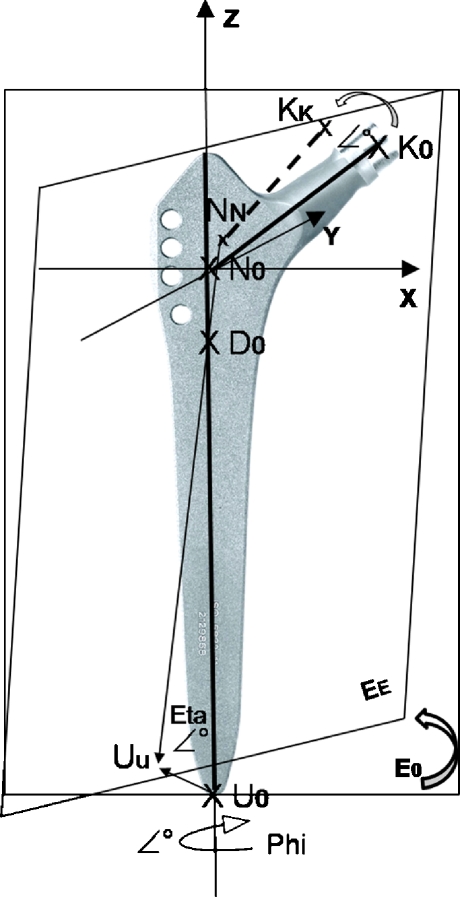
To calculate the correlation between the sagittal prosthesis tilt and the functional anteversion, a mathematical-geometrical plane model in 3D-space was developed using the Euler angles. The prosthesis position is described with the help of a 3D coordinate system. The Z-axis of the 3D coordinate system is defined by the proximal femoral axis and the X-axis by the condylar axis so that the Y-axis is located vertical on both. Via the three points of the prosthesis (bottom point U0, N0 and conus point K0), a plane E0 was defined. This plane can be rotated around the Z-axis in accordance with the rotatory anteversion (angle phi °). To simulate the sagittal tilt (angle eta °) the plane is rotated around the rotation point D0. This point was placed on the upper two third of the prosthesis axis and is the coincidence of the proximal femoral and stem axis. In dependence of the sagittal tilt and the rotatory anteversion, the location of the points UU, NN and KK in 3D-space (plane EE) can be calculated via a coordinate’s transformation using the Euler angles (phi and eta), and consequently the geometric relationships between sagittal tilt of the femoral component and the functional anterversion depending on the rotatory anteversion
There was a differentiation between rotational and functional anteversion. Rotational anteversion is the actual torsion of the prosthesis around the proximal femoral axis adjusted intraoperatively by the surgeon. This is calculated from the angle of the prosthesis neck axis to the condylar axis. The functional anteversion (under influence of the sagittal tilt) results from the angle between the connection line of the centre of the femoral head and the proximal femoral axis as well as of the condylar axis that runs through the proximal femoral axis (Fig. 1). If the prosthetic axis and proximal femoral axis coincide, rotational anteversion is equal to functional anteversion.
Mathematic–geometric model
A mathematic-geometric model was developed to calculate the geometric relationship between sagittal tilt of the femoral component and the functional anteversion depending on the rotatory anteversion. The calculation of the functional anteversion resulting from rotatory anteversion and sagittal tilting was performed by means of a 3D coordinate transformation in space using the Euler angles (phi, psi, and eta): In this model the prosthesis position in the femur is described with the help of a 3D coordinate system. The Z-axis of the 3D coordinate system is defined by the proximal femoral axis and the X-axis by the condylar axis so that the Y-axis is located vertical on both (Fig. 3). In general, the position of the prosthesis in this 3D coordinate system is described by three points N, U, K. If no sagittal tilt of the prosthesis exists the femoral axis and the prosthesis stem axis coincide. In this case the prosthesis position in the femur is characterized by means of the 3 points (N0, U0, K0) which clearly defines the prosthesis plane E0: The zero point N0 emerges from the intersection of the prosthesis axis and the prosthesis conus axis (intersection equals the CCD angle (131°)), and is located on the proximal femur axis in the case of 0° sagittal tilt of the stem. Furthermore N0 is also located at the zero point of the 3D coordinate system, on the femoral axis (z). Besides the zero point N0 (0, 0, 0), the bottom point U0 (0, 0,-L) of the prosthesis as well as the conus point K0 (B cos(eta) cos(phi), B cos(eta) sin(phi), B sin(eta)) serve to characterise the respective position of the prosthesis (B: length of the conus axis, L: distance between N and U) (Fig. 3). The position of the prosthesis as a function of the sagittal tilt is characterised by the points NN, UU and KK as well as by the resulting prosthesis plane EE. The 3D coordinate transformation of the plane E0 to EE (depending on the sagittal tilt and the rotatory anteversion) is calculated with the Euler angles. The sagittal tilt of the stem axis corresponds to the Euler angle Eta, the rotation of the prosthesis around the stem axis (rotatory anteversion) to the angle phi and a possible coronal tilt of the stem axis to the angle psi. The rotation point D of the prosthesis stem axis (coincidence point between proximal femoral and stem axis) is located on the femoral axis (fixed point, independent of stem tilting) and may be located above, mostly however below the zero point N0 (approx. upper 2/3 of the entire prosthesis length LP) and is characterised by the point D (0, 0, ~2/3 LP). This allows the calculation of the current position of the prosthesis characterised by the points NN, UU and KK as a function of the three Euler angles eta, phi and psi (3D coordinate transformation) and hence, the geometric relationships between sagittal tilt of the femoral component and the functional anteversion depending on the rotatory anteversion. The third Euler angle psi (prosthesis tilt in the frontal plane, along the X-axis, varus/valgus tilt) was set to 0 in the model. All calculations were performed with the mathematical software MathcadR 14.0 (Parametric Technology Corporation, Needham, USA).
Results
CT data
The average rotatory anteversion of the prosthesis stem in the study group was 8° (−11.6 to 26°) the functional anteversion 18° (6.2–37.2°). We determined an average difference between functional and rotatory anteversion of 10° (8.8–18°). The average stem tilt in the sagittal plane was 5.2° (0.7–9°) towards anterior. Table 1 shows a detailed listing of the individual values for each patient. Individual value pairs are shown in Fig. 4 for each patient.
Table 1.
Listing of rotatory, functional anteversion and stem deviation in the sagittal plane from the proximal femoral axis for each patient
| Patient | Rotatory anteversion (rAV) ° | Functional anteversion (fAV) ° | Deviation sagittal plane ° | fAV-rAV |
|---|---|---|---|---|
| 1 | −0,7 | 12,8 | 8,9 | 13,5 |
| 2 | −2,5 | 9,3 | 6,3 | 11,8 |
| 3 | 10,3 | 19,3 | 7,1 | 9,1 |
| 4 | 25,9 | 35,3 | 4,8 | 9,4 |
| 5 | 7,5 | 16,9 | 4,0 | 9,5 |
| 6 | 4,2 | 13,1 | 5,4 | 8,9 |
| 7 | 16,4 | 18,1 | 1,1 | 1,7 |
| 8 | −11,6 | 6,2 | 7,8 | 17,8 |
| 9 | 5,1 | 15,4 | 8,9 | 10,4 |
| 10 | 14,4 | 27,8 | 7,1 | 13,4 |
| 11 | 11,3 | 20,6 | 4,0 | 9,3 |
| 12 | 8,1 | 11,3 | 2,8 | 3,2 |
| 13 | −1,1 | 14,2 | 6,5 | 15,2 |
| 14 | 15,3 | 37,2 | 8 | 21,8 |
| 15 | 0,4 | 10,2 | 4,4 | 9,9 |
| 16 | 23,6 | 35,7 | 3,9 | 12,1 |
| 17 | 18,0 | 25,6 | 4,1 | 7,6 |
| 18 | 4,0 | 12,0 | 3,2 | 8,0 |
| 19 | 6,9 | 24,1 | 7,5 | 17,2 |
| 20 | 9,0 | 14,5 | 2,5 | 5,5 |
| 21 | 1,7 | 7,9 | 3,4 | 6,2 |
| 22 | −2,0 | 9,8 | 5,8 | 11,8 |
| 23 | 5,2 | 18,7 | 5,4 | 13,6 |
| 24 | 14,9 | 25,9 | 4,5 | 11,0 |
| 25 | 11,7 | 21,8 | 4,5 | 10,1 |
| 26 | 8,8 | 19,2 | 5,7 | 10,4 |
| 27 | 10,0 | 16,1 | 0,7 | 6,1 |
| 28 | 9,4 | 20,7 | 5 | 11,3 |
| 29 | 5,6 | 20,5 | 6 | 14,9 |
| 30 | 6,1 | 21,5 | 5,9 | 15.4 |
Fig. 4.
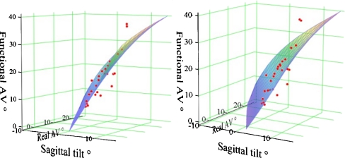
Illustration of the mathematical–geometrical correlation between rotatory anteversion (phi), prosthesis tilting in the sagittal plane (eta) and the resulting functional anteversion in a 3D diagram. (Real AV rotatory anteversion). The measured values for the patients are also displayed in the coordinate system (dots) and are approximately in the calculated plane
Mathematical–geometrical model
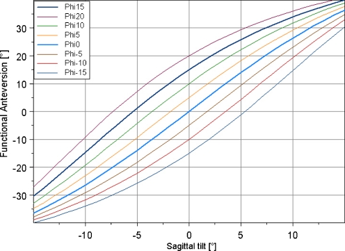
The 3D coordinate transformation using the Euler angles to calculate the mathematical–geometrical correlation between stem tilting in the sagittal plane and the influence on the functional anteversion in dependence of rotatory anteversion is illustrated in Fig. 4. The measured values for the patients are also displayed in the coordinate system (dots) and are approximately in the calculated plane. We determined a nonlinear mathematical correlation between functional anteversion and saggital tilting of the prosthesis, which is shown in Fig. 5 using a nomogram for fixed rotatory anteversion values phi (−15, −10, −5, 0, 5, 10, 15 and 20°).
Fig. 5.
Correlation between sagittal prosthesis tilting and functional anteversion (fAV) for fixed rotatory anteversion values (−15, −10, −5, 0, 5, 10, 15 and 20°)
Discussion
Instability and impingement are the most complex issues after THA, which can be attributed to different pathologies [5]. Recurrent dislocation is one of the most common reasons for THA failure, and the mechanism of recurrent dislocation is often difficult to find. One possible cause is malpositioning of the stem and cup [5]. This work illustrates the direct influence of stem tilting in the sagittal plane on anteversion of the prosthesis. In the group of patients examined, the resulting (functional) anteversion was on average approximately 10° above the actual (rotational) anteversion due to an average anterior tilting of the prosthesis axis towards the proximal femoral axis by approximately 5°. This shows that the anteversion desired by the surgeon is significantly increased in the case of anterior sagittal tilting. For example, a stem implanted at a 15° anteverted angle with a sagittal tilt by 2° towards anterior of the femoral axis results in a functional anteversion of 20°. This is quite a significant finding, as an unfavourable combined cup–stem alignment has a proven influence on the risk of impingement, the maximum range of motion, the extent of wear and dislocation or loosening [1, 6]. According to our study data, cup and stem should be implanted at a defined combined anteversion [4]. Depending on gender, a combined anteversion of 25–35° for men and 35–45° for women is desirable [12]. Widmer et al. defined the combined anteversion with the help of a formula based on a static model for an impingement-free range of motion (ROM) as: cup anteversion +0.7 × stem anteversion = 37.3°. So with a cup anteversion of, for example, 25°, a stem anteversion of approximately 18° [stem anteversion = (37.3° – cup anteversion)/0.7] would be desirable. According to our calculations, there would be an actual stem anteversion of approximately 27° in the case of an average sagittal stem tilt of 5° towards anterior, which would then lead to a combined total anteversion of approximately 52° instead of 37°. The example shows that a sagittal stem deviation has indeed a significant influence on total anteversion, which may even present an increased risk of dislocation or impingement in the case of a combined anteversion of >60° under the corresponding component constellation [9]. In this respect, CT is a useful analysis tool to display the exact alignment with the help of 3D reconstruction.
One noticeable fact was a clear variation of rotational stem anteversion in the study group, ranging from 11° retroversion to 26° anteversion. Other authors have also demonstrated a relative anteversion variance when using a noncemented straight stem whose average anteversion was 16°, with a variance from 30° retroversion up to 45° anteversion [4]. The relative scattering of the anteversion can be substantiated by the fact that the torsion of a noncemented straight stem due to press-fit anchoring is influenced by the individual structure of the femoral bone, the shape of the femur itself, femoral neck torsion and anterior bowing of the femur [3, 10]. These factors are also responsible for deviation in the sagittal plane in our opinion. When a bone-saving femoral-neck osteotomy is undertaken, these factors become especially important. This additionally shifts the femur entrance plane towards anterior and medial, which may also result in an anterior tilt of the stem axis due to ventralisation of the point of entry. In addition, the sagittal plane of the prosthesis may also shift towards anterior during stem preparation because the surgeon is indirectly diverted towards the anterior femuroral cortex with the rasp by the soft tissue and/or may also unconsciously tend to divert towards anterior to protect the muscles. The influence of sagittal tilting on functional stem anteversion shows the significance of this parameter for presurgical planning, exact prosthesis positioning during surgery and postoperative error analysis. So far, this parameter has rarely been considered for prosthesis positioning. Offset, CCD angle, varus/valgus malpositioning and anteversion have thus far been the essential parameters for 2D prosthesis planning. Obviously, however, the mere judgement of the prosthesis position using only one or two planes would seem to be insufficient. In our opinion, an exact 3D joint reconstruction is only possible using a navigation system if this can clearly reference the proximal femoral axis [4], as the surgeon cannot sufficiently evaluate the proximal femoral axis during surgery. This fact should encourage the development of a navigation system for exact placement of the femoral component taking the intrafemoral anatomy into account.
The obtained data from the group of patients and the model refer to a noncemented, tapered straight stem. However, the same principles can also be applied to cemented stems, as sagittal tilting may also occur in those instances. The calculated mathematical–geometrical model is shown to be a valid model that impressively reflects the influence of sagittal tilting on functional anteversion and offers the possibility of determining the actual (functional) anteversion in dependence on sagittal tilting. One critical factor of the model is that the rotation point (D) of the prosthesis was assumed to be constant in the model, as this cannot be determined individually for each patient. It was set to the point of transition from the upper to the centre third of the stem and is graphically verified by measuring values of the patients in the 3D plane. In this context, the differing variance of the individual measuring values from the plane must be attributed to a slight individual aberration of the prosthesis centre position in each patient. Altogether, the graphic correlation between the theoretical model and the actual measured values confirm the validity of the model so that the nomogram is suitable to depict the influence of sagittal stem tilting on anteversion, at least for the applied prosthesis design.
The study has some limitations. Although clinical in the sense that data were collected from actual patients rather than cadavers or models, there is no clinical evidence presented that sagittal tilt could influence the incidence of impingement or dislocation. Patients were not followed up to investigate the success, functionality, or relevance of the data. Further clinical studies are needed to establish the general applicability of these results as, for example, in a group of patients with demonstrable impingement or dislocation. Furthermore, the results are presented for the uncemented Zweymüller straight stem that can apparently be surgically placed in a relatively wide range of sagittal tilt angles. This is not the case for most cementless designs or for cemented femoral components designed for typical cement mantles. It would be valuable if for further particular prostheses, implanted by experienced surgeons, the sagittal tilt could be also related to the performance of the arthroplasty. This would provide valuable information, supported by the mathematical model, for perhaps less experienced surgeons to achieve improved clinical results.
In summary, we were able to demonstrate a definite association between sagittal stem alignment and the resulting femoral head centre, which has quite an influence on the functional stem anteversion depending on the anterior or posterior tilting of the stem. The mainly anterior prosthesis stem tilt in this investigation coincides with an increase in functional anteversion and at the same time with hyperextension in the joint region with neutral position of the femur, which may pose an increased risk of impingement as well as dislocation. Both aspects substantiate the necessity to analyse sagittal alignment of the prosthesis stem in the context of impingement and luxation diagnosis. Here, the 3D analysis of CT data sets as an additional diagnostic tool provides substantial benefits and in our opinion is to be recommended when using the nomogram developed in the course of this study.
Acknowledgment
We acknowledge and thank Dr. rer. nat. Bernd Müller from the Institute of Physical Chemistry of the Friedrich Schiller University Jena for the mathematical support and instruction.
Conflict of interest statement The authors have no conflict of interest to report. No specific funding was received.
References
- 1.Bicanic G, Delimar D, Delimar M, Pecina M. Influence of the acetabular cup position on hip load during arthroplasty in hip dysplasia. Int Orthop. 2009;33(2):397–402. doi: 10.1007/s00264-008-0683-z. [DOI] [PMC free article] [PubMed] [Google Scholar]
- 2.Cinotti G, Lucioli N, Malagoli A, Calderoli C, Cassese F (2010) Do large femoral heads reduce the risks of impingement in total hip arthroplasty with optimal and non-optimal cup positioning? Int Orthop [Epub ahead of print] [DOI] [PMC free article] [PubMed]
- 3.D’Lima DD, Urquhart AG, Buehler KO, Walker RH, Colwell CW., Jr The effect of the orientation of the acetabular and femoral components on the range of motion of the hip at different head-neck ratios. J Bone Joint Surg Am. 2000;82(3):315–321. doi: 10.2106/00004623-200003000-00003. [DOI] [PubMed] [Google Scholar]
- 4.Dorr LD, Malik A, Dastane M, Wan Z. Combined anteversion technique for total hip arthroplasty. Clin Orthop Relat Res. 2009;467(1):119–127. doi: 10.1007/s11999-008-0598-4. [DOI] [PMC free article] [PubMed] [Google Scholar]
- 5.Dorr LD, Wan Z. Causes of and treatment protocol for instability of total hip replacement. Clin Orthop Relat Res. 1998;355:144–151. doi: 10.1097/00003086-199810000-00015. [DOI] [PubMed] [Google Scholar]
- 6.Earll M, Fehring T, Griffin WL, Mason JB, McCoy TH. Early osteolysis associated with trunion-liner impingement. Clin Orthop Relat Res. 2004;418:153–156. doi: 10.1097/00003086-200401000-00024. [DOI] [PubMed] [Google Scholar]
- 7.Enocson A, Lapidus G, Tornkvist H, Tidermark J, Lapidus LJ (2010) Direction of hip arthroplasty dislocation in patients with femoral neck fractures. Int Orthop [Epub ahead of print] [DOI] [PMC free article] [PubMed]
- 8.Gallo J, Havranek V, Zapletalova J. Risk factors for accelerated polyethylene wear and osteolysis in ABG I total hip arthroplasty. Int Orthop. 2010;34(1):19–26. doi: 10.1007/s00264-009-0731-3. [DOI] [PMC free article] [PubMed] [Google Scholar]
- 9.Jolles BM, Zangger P, Leyvraz PF. Factors predisposing to dislocation after primary total hip arthroplasty: a multivariate analysis. J Arthroplasty. 2002;17(3):282–288. doi: 10.1054/arth.2002.30286. [DOI] [PubMed] [Google Scholar]
- 10.Maruyama M, Feinberg JR, Capello WN, D’Antonio JA. The Frank Stinchfield Award: morphologic features of the acetabulum and femur: anteversion angle and implant positioning. Clin Orthop Relat Res. 2001;393:52–65. doi: 10.1097/00003086-200112000-00006. [DOI] [PubMed] [Google Scholar]
- 11.Ranawat C, Maynard M. Modern techniques of cemented total hip arthroplasty. Tech Orthop. 1991;6:17–25. doi: 10.1097/00013611-199109000-00004. [DOI] [Google Scholar]
- 12.Widmer KH, Zurfluh B. Compliant positioning of total hip components for optimal range of motion. J Orthop Res. 2004;22(4):815–821. doi: 10.1016/j.orthres.2003.11.001. [DOI] [PubMed] [Google Scholar]
- 13.Ybinger T, Kumpan W. Enhanced acetabular component positioning through computer-assisted navigation. Int Orthop. 2007;31(Suppl 1):S35–S38. doi: 10.1007/s00264-007-0430-x. [DOI] [PMC free article] [PubMed] [Google Scholar]


