Abstract
Shell deformation of resurfacing and all-metal modular cups following press-fit implantation has been reported, but not for conventional metal-backed cups with polyethylene liners. The deformation of acetabular components with historical and thin polyethylene inserts after press-fit insertion was evaluated using a cadaveric model. All shells and liners deformed upon implantation. Following joint loading, shell pinch decreased from 0.32 to 0.22 mm (p = 0.019) and from 0.29 to 0.13 mm (p = 0.003) for the thin and thick liner groups, respectively. Liner pinch also decreased from 0.17 to 0.04 mm (p = 0.031) and from 0.06 to 0 mm (p = 0.103) for the thin and thick liner groups, respectively. There were no significant differences between the thin and thick liners. Liner deformation was influenced by the initial shell deformation and donor bone quality. Shell and liner pinch decreased following joint loading, suggesting a settling in effect.
Introduction
The use of press-fit acetabular components in total hip arthroplasty is currently well accepted clinically for achieving long-term fixation. These systems use a hemispherical component that is typically implanted in a 1- to 2-mm under-reamed acetabulum. Initial fixation is achieved by the generation of frictional forces secondary to radial compressive forces at the periphery of the acetabulum [1]. These compressive forces may also cause the acetabular components to deform as a result of the compressive forces experienced during press-fit implantation and may be non-uniform in nature due to rim loading by dense cortical bone along the anterosuperior and posteroinferior margins of the acetabulum [2, 3]. The magnitude of these deformations is also affected by the potential variability of the acetabular surface geometry during reaming [4–6].
Shell deformation has historically not been of clinical concern, particularly with traditional stiff metal-backed cups with thick ultra-high molecular weight polyethylene (UHMWPE) liners, or in stiff Co-Cr metal inserts that can re-expand shells upon insertion [2]. However, shell deformation may have potential clinical consequences, especially when contemporary, thinner cup assemblies are used. For example, diametrical pinching deformations of up to 100 μm during cadaveric implantation of resurfacing cups have been reported [2], which could aversely affect the fluid film lubrication of metal-on-metal bearings and result in increased wear. Shell deformation can also complicate intraoperative assembly of ceramic inserts onto the shell [7].
Thinner cup assemblies have the advantage of allowing the use of larger femoral heads to reduce the risk of hip dislocation [8], while maintaining the outer shell diameter to preserve acetabular bone stock. Although increasing head size can reduce the contact pressure between the femoral head and polyethylene, the reduction in liner thickness may increase stresses within the polyethylene liner [9] and subsequent wear rates [10, 11]. However, it is expected that the use of annealed highly cross-linked polyethylene, which has demonstrated increased wear resistance compared to conventional UHMWPE [12], will enable the efficacious use of larger femoral heads in metal-on-polyethylene hip systems. While previous studies have demonstrated shell deformation of all-metal modular cups and resurfacing cups following press-fit implantation, the extent of shell deformation in conventional metal-backed cups with polyethylene liners is not known at present. Furthermore, it is unclear whether the shell deformation affects the polyethylene liner geometry and if polyethylene thickness affects the overall cup deformation.
The objective of the study was to use a cadaveric model to evaluate the effect of liner thickness on the deformation of a contemporary acetabular component during implantation and subsequent simulated gait loading. Interaction between liner and shell deformation was examined in order to quantify both shell and liner deformation.
Materials and methods
Cadaver experiments in this study were conducted using six fresh frozen pelves (LifeLegacy Foundation, Tucson, AZ, USA). The specimens comprised three male and three female donors, whose ages ranged from 30 to 50 years old. Detailed demographics of the donors are presented in Table 1. All testing was performed under the approval of an Institutional Review Board.
Table 1.
Demographics of cadaver hip donors
| Specimen ID | Age | Height (in) | Weight (lbs) | Gender | BMD (g/cm2) | T-score |
|---|---|---|---|---|---|---|
| PS4 | 30 | 71 | 290 | M | 1.20 | 2.1 |
| PS6 | 42 | 64 | 230 | F | 1.10 | 1.3 |
| PS7 | 49 | 62 | 130 | F | 1.10 | 1.3 |
| PS8 | 45 | 70 | 320 | F | 1.02 | 0.7 |
| PS12 | 40 | 74 | 258 | M | 1.23 | 1.3 |
| PS14 | 50 | 73 | 175 | M | 1.37 | 2.3 |
BMD bone mineral density
All cadaver pelves underwent bilateral total hip arthroplasty by a trained surgeon (DCM) with insertion of a titanium alloy Trident I PSL system (Stryker Orthopaedics, Mahwah, NJ, USA). The Trident PSL shells are designed to maximise fixation in the peripheral lunate region. The dual sphere and terraced geometry (normalisations) of the shells allows more load to be preferentially distributed to the denser bone in the lunate region because the rim sphere diameter is a nominal 0.8 mm larger than the diameter at the dome. This patented design results in an interference fit at the rim of the acetabulum of 1.8 mm, while allowing a 1 mm fit to the medial acetabular wall. For each cadaver specimen, a thin polyethylene insert was implanted in a randomly selected side, and a historical thick polyethylene insert was used on the contralateral side as a paired control. Each acetabulum was manually reamed to its clinically appropriate size with a nominal diametral press-fit at the equator of 1.8 mm. Matched shell sizes were used for the contralateral side of each hip, allowing direct paired comparison of the effect of liner thickness for each hip. A total of three shell sizes (50, 54 and 58 mm) were implanted in the six hips, with two pelves per shell size (Table 2). The 50- and 54-mm shells have the same thicknesses at the rim (3.8 mm) and dome (3.3 mm), while the 58-mm shell is slightly thicker at the rim (4.2 mm) and dome (3.7 mm).
Table 2.
Experimental design
| Specimen ID | Left side | Right side | ||||||
|---|---|---|---|---|---|---|---|---|
| PE group | Shell size (mm) | PE size (mm) | PE thickness (mm) | PE group | Shell size (mm) | PE size (mm) | PE thickness (mm) | |
| PS4 | Thick | 54 | 32 | 9.9 | Thin | 54 | 44 | 3.8 |
| PS6 | Thick | 50 | 32 | 7.9 | Thin | 50 | 40 | 3.8 |
| PS7 | Thick | 54 | 32 | 9.9 | Thin | 54 | 44 | 3.8 |
| PS8 | Thin | 50 | 40 | 3.8 | Thick | 50 | 32 | 7.9 |
| PS12 | Thin | 58 | 44 | 5.4 | Thick | 58 | 32 | 11.4 |
| PS14 | Thick | 58 | 32 | 11.4 | Thin | 58 | 44 | 5.4 |
The liners were modified slightly to allow measurement of changes in shell diameter at the shell-liner interface; 2.5-mm radius cylinders, centred at the outer edge of the rim, were machined every 30° between the derotational insets. These localised modifications were judged not to affect the overall shell and liner deformations.
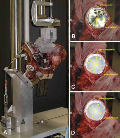
Shell diameter was measured using a digital caliper (Mitutoyo Corporation, Aurora, IL, USA) at four locations: two of which corresponded to ±15° from the main anterosuperior (A-S) axis and two of which corresponded to ±15° from the main anteroinferior (A-I) axis (Fig. 1). The main A-S axis was defined as the axis through the centre of the shell and the central superior screw hole. The main A-I axis was the axis perpendicular to the main A-S axis. The locations of the shell measurements corresponded to the machined regions on the liner, as described above. Measurements were not taken at the main A-S and A-I axes in order to avoid modification of the derotational insets.
Fig. 1.
Experimental set-up on the MTS (a). The hip is mounted in an anatomical orientation and stabilised through passive cables at the attachment points of the major abductors. Locations of the shell measurements with (b) and without (c) the liner present and liner measurements (d) are also shown on the right with respect to the anterosuperior (A-S) and anteroinferior (A-I) axes
Shells were measured in each orientation three times at six time points: (1) pre-implantation, (2) post-implantation, (3) post-liner insertion, (4) after a minimum of 30 min post-implantation for possible bone relaxation and implant settling (creep), (5) pre-mechanical loading and (6) post-mechanical loading. The measurements were taken by two observers at different time points during the experiment. The inter-observer variability was verified for each observer through five repeated measurements of an exemplar insert and shell. Details of mechanical loading are provided below. The final measurement at each time point was calculated as the average of the three repeated readings.
The inner diameters of the liners were also measured along the main A-S and A-I axes using the digital calipers. Liner measurements were taken three times in each orientation at five time points: (1) pre-implantation, (2) post-implantation, (3) after a minimum of 30 min post-implantation for possible bone relaxation and implant settling (creep), (4) pre-mechanical loading and (5) post-mechanical loading. The final measurement at each time point was calculated as the average of the three repeated readings.
One of the possible clinical consequences of liner deformation during implantation is its effect on head-liner clearance or impingement. The extent of head-liner impingement or “pinch” was defined at each time point as the difference between the recorded liner diameter and the head diameter. Shell pinch was defined as the difference between the recorded shell diameter and nominal diameter based on the design drawings. Additionally, “out of roundness” was defined as half of the difference between the measured maximum and minimum diameters and was used to describe the extent of non-sphericity following deformation.
Each cadaver specimen was mounted on a mechanical testing system (MTS, Mini-Bionics, Eden Prairie, MN, USA) in anatomical orientation [1]. Each pelvis was suspended from the upper actuator of the MTS through the sacrum, which was plated to an x-y table assembly to allow translational freedom of the entire pelvis. The specimen was then lowered onto a rigid fixture upon which the appropriately sized femoral head for each acetabulum was mounted (Fig. 1). A series of passive cables mounted through the pelvis at the attachment points of the major abductors provided stability of the pelvis. External loading was applied vertically through the sacrum in displacement control to a maximum static load of 2,200 N. The load was then released and cycled ten times between 100 and 1,200 N at 0.1 Hz. The hip was cycled at a lower load magnitude compared to the static load to maintain joint stability. After loading one side of the hip, the contralateral side was tested using the same procedure.
Differences in deformation (pinch and out of roundness) between groups were tested statistically using paired t tests. These were compared immediately after insertion (“insertion”) and after mechanical loading (“final”). During cup insertion, the acetabulum of one specimen (PS14) cracked and therefore was not included in the paired t tests to maintain equal sample sizes between thin and thick liner groups. Using all specimens, a predictive model for final liner deformation was constructed using stepwise linear regression analysis (JMP, SAS Institute Inc., Cary, NC, USA) with donor as a random effect and liner type (thin/thick), bone mineral density (BMD), initial shell deformation and an interaction term for BMD with initial shell deformation as explanatory variables. A p value of less than 0.05 was used to determine the statistical significance between variables.
Results
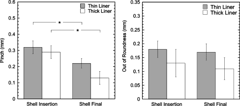
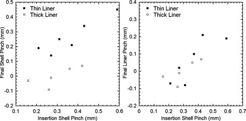
All shells were deformed following impaction into the surgically prepared pelves, but the magnitude of shell pinch decreased after insertion of the liner and application of loading. After mechanical loading, the average shell pinch decreased significantly from 0.32 to 0.22 mm for the thin liner group (p = 0.019) and from 0.29 to 0.13 mm for the thick liner group (p = 0.003) (Fig. 2). The final shell pinch tended to increase with greater initial shell deformation (r2 = 0.50, Fig. 3). Although final shell deformation was higher for the thin liners, the difference was not significant (p > 0.106).
Fig. 2.
Shell pinch (left) and out of roundness (right) immediately after insertion and after mechanical loading (final) (mean±SEM; *p < 0.05). Results from PS14 were excluded because of cracking of the acetabulum in one side during insertion
Fig. 3.
Final vs initial shell pinch (left) and final liner pinch vs initial shell pinch (right)
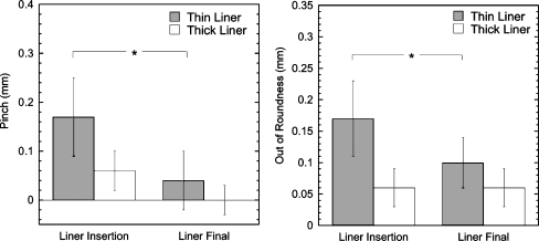
The average initial thin and thick liner pinch averaged 0.17 mm (range: 0–0.40 mm) and 0.06 mm (range: −0.07 to 0.16 mm), respectively (Fig. 4). The initial thin and thick liner out of roundness averaged 0.17 mm (range: 0.05–0.31 mm) and 0.06 mm (range: 0–0.13 mm), respectively. There was no significant difference in the initial liner pinch or out of roundness between the thick and thin liner groups (p > 0.199), though the largest deformations were recorded for the thin liners (PS6 and 8). The average liner pinch decreased from 0.17 to 0.04 mm for the thin liner group (p = 0.031) and from 0.06 to 0 mm for the thick liner group (p = 0.103). The final liner pinch and out of roundness were not significantly different between the thick and thin liners (p > 0.555).
Fig. 4.
Liner pinch (left) and out of roundness (right) immediately after insertion and after mechanical loading (final) (mean±SEM; *p < 0.05). Results from PS14 were excluded because of cracking of the acetabulum in one side during insertion
For both liner groups (thick or thin), final liner pinch tended to be greater when the initial shell deformation was greater (r2 = 0.67, Fig. 3). Although shell pinch was not correlated between sides of the pelvises (within donors), there was a trend of a greater amount of shell pinch for specimens with higher BMD. The results of stepwise linear regression indicated that BMD (p = 0.034) and the interaction between shell deformation and BMD (p = 0.002) were significant predictors of liner deformation, but not donor or liner type.
Discussion
In this study, a cadaveric model was used to determine the magnitude of shell and liner diametral deformation (pinching and out of roundness) for Trident acetabular components with both standard and thin polyethylene inserts. We used young donor cadavers, with a target press-fit of 1.8 mm to provide a conservative worst-case scenario for testing. The shell pinch measured in this study was in the same range as those measured in previous foam block, in vitro, and in vivo experiments [2, 3].
We observed that the pinch deformation of the shell decreased between shell insertion and the final time point while the out of roundness did not change. This suggests that there was a “settling in” effect where the combined effects of liner insertion, viscoelastic creep and plastic deformation of the bone under loading led to the entire cup opening slightly in all directions, thus reducing pinch but not final out of roundness. Although the thin and thick liner deformations were not significantly different, changes in the liner deformation due to joint loading were predominantly observed in the thin liners. This was probably due to the greater compliance of the thinner liner when loaded by the femoral head.
A limitation of this study was that we were only able to load each hip to 2,200 N for one loading cycle and that subsequent loading cycles were limited to 1,200 N. This reduced loading was used because we experienced some instability of the sacroiliac joints and pubic symphysis during preliminary testing. The use of a limited number of cycles of reduced loading may lead to an underestimation of the final “settling in” of the device. Additionally, it is likely that bone remodelling and long-term settling of the device would further affect cup deformation. It has been demonstrated that gaps between press-fit cups and the surrounding bone can close over time [13, 14] and that periprosthetic BMD continues to change for five years after cementless hip replacement [4]. The resulting long-term changes of load transfer could redistribute loading away from the rim.
The final shell and liner deformation (pinch and out of roundness) tended to be greater for the thin liners compared to the thicker liners, but it was evident that donor BMD and initial shell deformations were stronger predictors of final deformation. Although the same shell designs were used for both liner groups, the thin liners were generally implanted into shells that were initially more deformed and in specimens with better bone quality. The relation between BMD and shell deformation has been noted previously in an in vivo study of press-fit components with a 1-mm interference [3]. The strong relation between initial and final shell deformations in our study indicates that surgical technique is likely to be an important factor for pinching of both thin and thick liners. It is known that manual reaming results in a reamed geometry that is ellipsoidal, rather than spherical [4]. Deviation from a hemispherical reamed geometry will further affect bony contact and contribute to a pinching deformation of the shell.
The presence of shell and liner deformation could have potential clinical consequences in terms of polyethylene fracture, volumetric wear rate and insert stresses. However, it is likely that the use of highly cross-linked polyethylene will alleviate some of these concerns due to the relatively low wear rates compared to conventional polyethylene [12, 15]. Further, previous computational analyses of selected pinched cup geometries have demonstrated a low risk of liner fracture, while maintaining relatively low volumetric wear compared to conventional polyethylene [16]. Care, however, should be taken in extrapolating these results to other configurations. It has been demonstrated that cup design affects the bony support behind the cup, which can in turn affect the overall deformation of the cup [17–19]. In addition, less than optimal positioning of the cup could result in increased wear. For example, it is known that elevated stresses and rim loading can occur in thin liners when implanted with greater abduction angles [8, 20]. In our study, we did not examine the effect of orientation but intended to achieve natural reconstruction.
The maximum shell deformation of 430 μm in this study (Fig. 3) is consistent with previous measurements of all-metal modular cup and resurfacing cup deformation following press-fit implantation [2, 3]. Intraoperatively, the titanium alloy Pinnacle 100 (DePuy, Warsaw, IN, USA) cup produced an average shell deformation of 160 μm (range: 0–570 μm) [3]. Compared with our findings, resurfacing cups exhibited smaller deformations of up to 123 μm in cadaver specimens and polyurethane foam blocks [2], which probably reflects the use of higher modulus implant material (Co-Cr alloy) for the resurfacing cups. Although some of these reported deformations exceed standard head-liner diametral clearances (40–240 μm), the viscoelastic response of the periprosthetic bone following cyclic joint loading may allow re-expansion of the implant and restoration of the intended head-liner radial clearance.
Although we observed cup deformation in this study, we do not anticipate that this will result in unreasonably elevated wear in thin highly cross-linked polyethylene liners. The amounts of in vivo deformations are likely dependent on the extent of bony support (e.g. bone quality, reamed bone geometry), surgical variables (e.g. cup positioning) and implant design (e.g. diameter, thickness, amount of intended press-fit, type of locking mechanism). It is, however, unclear at present how pinching may affect joint lubrication or bone-implant interface micromotion (and subsequent fixation) for cups with thin polyethylene liners.
Acknowledgements
Research funding from Stryker Orthopaedics, Inc.
References
- 1.Widmer KH, Zurfluh B, Morscher EW. Load transfer and fixation mode of press-fit acetabular sockets. J Arthroplasty. 2002;17:926–935. doi: 10.1054/arth.2002.34526. [DOI] [PubMed] [Google Scholar]
- 2.Lin ZM, Meakins S, Morlock MM, Parsons P, Hardaker C, Flett M, Isaac G. Deformation of press-fitted metallic resurfacing cups. Part 1: experimental simulation. Proc Inst Mech Eng H. 2006;220:299–309. doi: 10.1243/095441105X69150. [DOI] [PubMed] [Google Scholar]
- 3.Squire M, Griffin WL, Mason JB, Peindl RD, Odum S. Acetabular component deformation with press-fit fixation. J Arthroplasty. 2006;21:72–77. doi: 10.1016/j.arth.2006.04.016. [DOI] [PubMed] [Google Scholar]
- 4.Kim YS, Brown TD, Pedersen DR, Callaghan JJ. Reamed surface topography and component seating in press-fit cementless acetabular fixation. J Arthroplasty. 1995;10(Suppl):S14–S21. doi: 10.1016/S0883-5403(05)80226-8. [DOI] [PubMed] [Google Scholar]
- 5.MacKenzie JR, Callaghan JJ, Pedersen PR, Brown TD. Areas of contact and extent of gaps with implantation of oversized acetabular components in total hip arthroplasty. Clin Orthop Relat Res. 1994;298:127–136. [PubMed] [Google Scholar]
- 6.Schwartz JT, Jr, Engh CA, Forte MR, Kukita Y, Grandia SK. Evaluation of initial surface apposition in porous-coated acetabular components. Clin Orthop Relat Res. 1993;293:174–187. [PubMed] [Google Scholar]
- 7.Langdown AJ, Pickard RJ, Hobbs CM, Clarke HJ, Dalton DJ, Grover ML. Incomplete seating of the liner with the Trident acetabular system: a cause for concern? J Bone Joint Surg Br. 2007;89:291–295. doi: 10.1302/0301-620X.89B3.18473. [DOI] [PubMed] [Google Scholar]
- 8.Crowninshield RD, Maloney WJ, Wentz DH, Humphrey SM, Blanchard CR. Biomechanics of large femoral heads: what they do and don’t do. Clin Orthop Relat Res. 2004;429:102–107. doi: 10.1097/01.blo.0000150117.42360.f9. [DOI] [PubMed] [Google Scholar]
- 9.Bartel DL, Bicknell VL, Wright TM. The effect of conformity, thickness, and material on stresses in ultra-high molecular weight components for total joint replacement. J Bone Joint Surg Am. 1986;68:1041–1051. [PubMed] [Google Scholar]
- 10.Learmonth ID, Hussell JG, Smith EJ. Inadequate polyethylene thickness and osteolysis in cementless hip arthroplasty. J Arthroplasty. 1997;12:305–309. doi: 10.1016/S0883-5403(97)90027-9. [DOI] [PubMed] [Google Scholar]
- 11.Lee PC, Shih CH, Chen WJ, Tu YK, Tai CL. Early polyethylene wear and osteolysis in cementless total hip arthroplasty: the influence of femoral head size and polyethylene thickness. J Arthroplasty. 1999;14:976–981. doi: 10.1016/S0883-5403(99)90013-X. [DOI] [PubMed] [Google Scholar]
- 12.Dumbleton JH, D’Antonio JA, Manley MT, Capello WN, Wang A. The basis for a second-generation highly cross-linked UHMWPE. Clin Orthop Relat Res. 2006;453:265–271. doi: 10.1097/01.blo.0000238856.61862.7d. [DOI] [PubMed] [Google Scholar]
- 13.Ng FY, Zhu Y, Chiu KY. Cementless acetabular component inserted without screws—the effect of immediate weight-bearing. Int Orthop. 2007;31:293–296. doi: 10.1007/s00264-006-0189-5. [DOI] [PMC free article] [PubMed] [Google Scholar]
- 14.Roth A, Winzer T, Sander K, Anders JO, Venbrocks RA. Press fit fixation of cementless cups: how much stability do we need indeed? Arch Orthop Trauma Surg. 2006;126:77–81. doi: 10.1007/s00402-005-0001-9. [DOI] [PubMed] [Google Scholar]
- 15.Herrera L, Lee R, Essner A, Longaray J, Wang A, Dumbleton JH, Lovell T (2007) Hip simulator evaluation of the effect of femoral head size and liner thickness on the wear of sequentially crosslinked acetabular liners. 53rd Annual Meeting of the Orthopaedic Research Society
- 16.Ong KL, Rundell S, Liepins I, Laurent R, Markel D, Kurtz S. Biomechanical modeling of acetabular component polyethylene stresses, fracture risk, and wear rate during press-fit implantation. J Orthop Res. 2009;27:1467–1472. doi: 10.1002/jor.20918. [DOI] [PubMed] [Google Scholar]
- 17.Berli BJ, Ping G, Dick W, Morscher EW. Nonmodular flexible press-fit cup in primary total hip arthroplasty: 15-year followup. Clin Orthop Relat Res. 2007;461:114–121. doi: 10.1097/BLO.0b013e3180592a79. [DOI] [PubMed] [Google Scholar]
- 18.Howard JL, Hui AJ, Bourne RB, Holdsworth DW. Computed tomographic analysis of bone support for three acetabular cup designs. Clin Orthop Relat Res. 2005;434:163–169. doi: 10.1097/01.blo.0000151442.60652.ac. [DOI] [PubMed] [Google Scholar]
- 19.Ong KL, Lehman J, Notz WI, Santner TJ, Bartel DL. Acetabular cup geometry and bone-implant interference have more influence on initial periprosthetic joint space than joint loading and surgical cup insertion. J Biomech Eng. 2006;128:169–175. doi: 10.1115/1.2165701. [DOI] [PubMed] [Google Scholar]
- 20.Kennedy JG, Rogers WB, Soffe KE, Sullivan RJ, Griffen DG, Sheehan LJ. Effect of acetabular component orientation on recurrent dislocation, pelvic osteolysis, polyethylene wear, and component migration. J Arthroplasty. 1998;13:530–534. doi: 10.1016/S0883-5403(98)90052-3. [DOI] [PubMed] [Google Scholar]


