Abstract
Porcelain-veneered alumina crown restorations often fail from bulk fracture resulting from radial cracks that initiate at the cementation surface with repeated flexure of the stiffer crown layers on the soft dentin support. We hypothesized that bulk fracture may be substantially mitigated by grading the elastic modulus at the crown surfaces. In this study, we fabricated graded structures by infiltrating glass into dense alumina plates, resulting in a diminished modulus at the surface layers. The plates were then bonded to polycarbonate substrates and subjected to fatigue loading in water. Tests were terminated when fracture occurred at the cementation tensile surface or at the fatigue endurance limit (1 million cycles). Infiltrated specimens showed a significant increase in fatigue fracture loads over non-infiltrated controls. Our results indicate that controlled elastic gradients at the surface could be highly beneficial in the design of fracture-resistant alumina crowns.
Keywords: alumina crowns, surface infiltration by glass, functionally graded ceramics, modulus gradient, sliding-contact fatigue, bulk fracture
Introduction
As a restorative material, alumina has better aesthetic values than zirconia, i.e., better translucency coupled with a more natural tooth-like shade (Heffernan et al., 2002). In addition, alumina has a thermal diffusivity (1.0 x 10⁻⁵ m2 sec−1) higher than that of zirconia (7.4 x 10⁻⁷ m2 sec−1), which allows alumina to be more effective in dissipating heat (Swain, 2009). Zirconia, with a lower thermal diffusivity, is more prone to generating high tensile residual stresses in the porcelain veneer, leading to premature veneer chipping or fracture, as theoretically predicted with flat specimens (Swain, 2009). However, alumina has a relatively low flexural strength, which makes alumina-based restorations susceptible to bulk fracture (Kelly, 1997; Oden et al., 1998; Hermann et al., 2006; Kokubo et al., 2009). One way to overcome this problem is to strengthen alumina by grading the material composition with a lower modulus at the tensile surfaces (Huang et al., 2007; Zhang and Ma, 2009).
Previously, we have demonstrated the feasibility of surface grading by infiltrating pre-sintered zirconia templates with a low-modulus glass of similar coefficient of thermal expansion (CTE) (Zhang and Kim, 2009). Such a gradation is able to diminish the tensile stress intensity at the plate surfaces (Jitcharoen et al., 1998; Zhang and Ma, 2009), rendering the structure less susceptible to flexural (Zhang et al., 2010) and contact (Kim et al., 2010; Zhang and Kim, 2010) damage. Here, we infiltrate a fully sintered and more aesthetically pleasing alumina system (relative to zirconia) with a low-modulus glass of similar CTE, creating a graded alumina-glass structure. We provide a quantitative analysis of the effects of a graded modulus on the fatigue load-bearing capacity of alumina-glass crown-like layer structures and demonstrate that a graded alumina-glass surface layer can effectively improve the fatigue strength of alumina. This novel alumina-glass material with enhanced flexural strength, aesthetics, and cementation properties may spark renewed interest in alumina-based dental restorations.
Materials & Methods
The alumina material used to produce graded structures is a dense, 99.5% pure, fine-grain alumina (AD995, CoorsTek, Golden, CO, USA). This material has a flexural strength of 572 MPa and a CTE of 8.2 x 10⁻⁶°C−1 (Zhang and Lawn, 2004). These properties are comparable with those of commercial dental alumina. A slurry containing a silicate glass composition with matching CTE (8.1 x 10⁻⁶°C−1, from 25 to 450°C) was applied to the top and bottom surfaces of sintered alumina plates. The main composition (> 1 wt%) of the infiltrating glass, as determined by x-ray fluorescence, is: SiO2 (71.6%), Al2O3 (10.5%), K2O (8.0%), Na2O (6.9%), and CaO (1.3%). CTE of the infiltrating glass was determined by means of a dilatometer (L75VD1600, LINSEIS, Princeton Junction, NJ, USA); specimens (6 x 6 x 35 mm) were prepared by casting molten glass in a graphite die. The coated plates were then heated to 1550°C for 2 hrs, producing an infiltrated glass/alumina/glass (GAG) structure. Heating and cooling rates were 600°C/hr. After specimens were cooled, the excess glass on both top and bottom surfaces was removed by polishing with a 6-µm and 0.5-µm diamond paste. Twenty flat specimens each for GAG and monolithic alumina control were prepared (23 mm in diameter and 1.45 mm thick). Three specimens from each group were bisected along a diameter-line segment; these cross-sections were polished to 0.5-µm finish. The polished cross-sections of half of the bisected plates were indented with a Berkovich diamond tip with an instrumented indentation device (Nanoindenter XP, MTS Systems Corp., Oakridge, TN, USA) with a maximum force of 500 mN. The indenter tip was loaded and unloaded at a rate of 10 mN/sec. An array of indents was made from the specimen surface to the interior, with a step size of 20 µm. The reduced modulus was determined by the Oliver-Pharr approach (Oliver and Pharr, 1992) from the indentation curve. The Young’s modulus of the specimen was computed according to the measured reduced modulus. [The reduced modulus E r is described by the relationship , with E and ν being the Young’s modulus and Poisson’s ratio of the indenter (i) or tested sample(s), respectively. For a diamond indenter tip, E i is 1140 GPa and νi is 0.07. For alumina, glass, and graded alumina-glass materials, νs is 0.22.] The other half of the bisected plates was carbon-coated on the polished section for microstructural analysis by scanning electron microscopy (SEM, Hitachi 3500N, Tokyo, Japan).
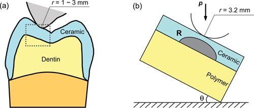
Seventeen plates from each group were bonded to polycarbonate bases with epoxy, simulating ceramic restorations cemented to dentin structures. Hertzian indentation fatigue tests were performed on this ceramic/polycarbonate bilayer structure with a spherical tungsten carbide (WC) indenter of radius r = 3.2 mm in water with a mouth-motion simulator (Elf 3300, EnduraTEC Division of Bose, Minnetonka, MN, USA) at 2 Hz. The specimen was mounted on an inclined block (θ = 30°, Fig. 1), simulating the cusp inclination angle (DeLong and Douglas, 1983; JH Kim et al., 2008). Load was applied in the vertical direction, but the loading consisted of a contact-load-slide-liftoff sequence—the indenter coming into contact with the specimen, loading to a maximum while sliding down the surface to create a wear facet, unloading, and lifting off from the specimen surface. Failure of the ceramic layer on a compliant substrate was defined when cementation (intaglio) surface radial cracks ‘popped in’ (i.e., bulk fracture). Damage sustained in fatigued specimens was examined by 3D polarized specular reflection microscopy (Edge R400, Micro Science Technologies, Marina Del Rey, CA, USA).
Figure 1.

Schematic of molar tooth occlusal contact. (a) Tooth-tooth contact. (b) Experimental set-up for sliding-contact fatigue of ceramic restoration layer on dentin-like compliant substrate (bilayer) with an inclination angle θ. Showing cementation surface radial cracks (R). Note that (b) represents the area highlighted by the gray dashed-line box in (a).
The current fatigue tests were designed to determine the number of cycles to failure, n F, for a range of prescribed fatigue loads 200 N to 1000 N. At least 3 specimens were tested for each prescribed fatigue load. Damage maps (load-cycles-type of failure) were constructed for graded GAG and monolithic alumina on compliant substructures. To create an intercept that was interpretable as the mean load, rather than a null load, we subtracted the mean load of 710 N from each test load value. Then, a linear regression model was fit to predict the number of log10 cycles to failure as a function of the centered test load, material (GAG or alumina), and their interaction. Statistical tests that yielded p-levels < 0.05 were considered significant.
Fatigued specimens were subjected to post mortem damage examination by optical microscopy (B Kim et al., 2007). Three graded and 3 ungraded specimens, following fatigue loading at 200 N for 1 million cycles, were selected for surface topography and roughness measurements across the center of the wear crater by 3D optical profilometry (Microphase DMC 100, The Digital Wavefront Company, Seattle WA, USA).
Results
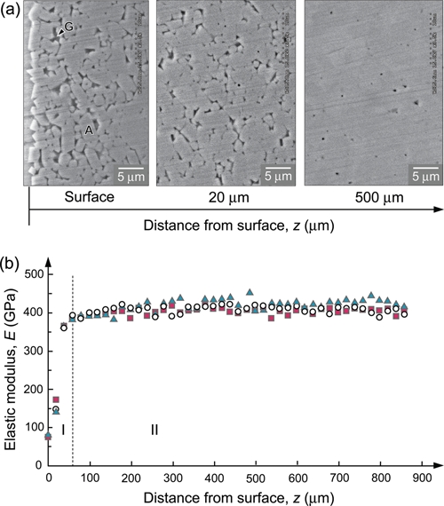
SEM analysis revealed a relatively high glass content at the graded alumina-glass surface (Fig. 2a). The glass content gradually decreased as the distance from the surface increased; eventually, the graded alumina-glass layer merged with a highly crystalline alumina core (Fig. 2a). Nanoindentations confirmed a relatively low Young’s modulus at the hybrid alumina-glass surface, which rose rather quickly to the bulk modulus of alumina as the distance from the surface increased (Fig. 2b). The thickness of the graded layer, according to nanoindentation, was approximately 60 µm.
Figure 2.

Microstructural and mechanical properties of graded glass/alumina/glass (GAG) structures. (a) SEM image of the surface of a graded alumina-glass layer (left), 20 µm into the graded zone (center), and an alumina core (right). Note: G and A represent glass and alumina phases, respectively. (b) The Young’s modulus profile across section of infiltrated GAG, plotted as function of distance z from outer surface. Note gradation of values within graded zone (I), and constant value within bulk (II). Different symbols represent separate tests on 3 GAG specimens.
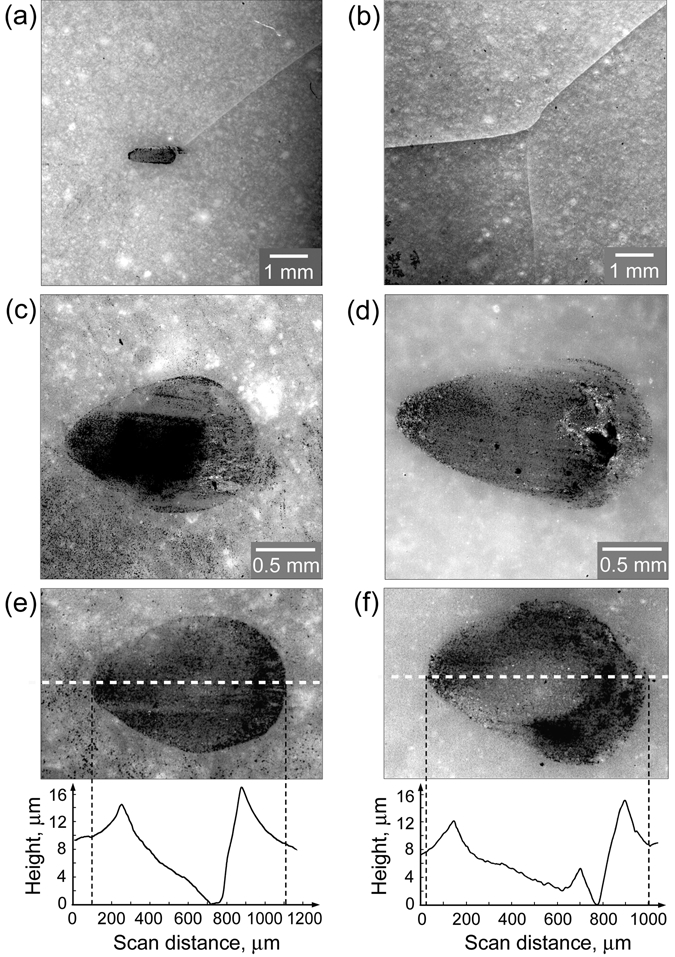
Typical damage patterns of ceramic/polycarbonate bilayers after subjection to sliding-contact fatigue are presented in the optical micrographs (Fig. 3). Cementation view revealed a classic flexural radial crack pattern, with multiple arms emanating from the fracture origin beneath the contact area (Fig. 3b). Occlusal view revealed that only one of the radial crack arms has extended to the top surface (Fig. 3a). In addition, a typical teardrop-shaped wear track induced from the sliding contact (sliding direction from left to right of the images) was also evident from the occlusal surface (Fig. 3a). The example shown here is an alumina/polycarbonate bilayer specimen after sliding-contact fatigue at 608 N for 108 cycles. However, similar fracture patterns were observed in all specimens, except for those that survived (without radial fracture) after the endurance limit (1 million loading cycles) was reached.
Figure 3.

Post mortem optical micrographs showing top (occlusal) and bottom (cementation) views of ceramic/polycarbonate bilayers subjected to sliding-contact fatigue with tungsten carbide sphere of radius r = 3.2 mm, in water. (a) Occlusal and (b) cementation views of alumina/polycarbonate bilayer subjected to sliding-contact fatigue at P = 608 N, n F = 108 cycles. (c,d) Occlusal views of sliding-contact damage sustained in homogeneous alumina and graded GAG following 1 million cyclic loadings at 480 N and 682 N, respectively. (e,f) Occlusal views of alumina and GAG following 1 million sliding-contact cycles at 200 N. The sliding direction is from left to right of the images. In (e) and (f), white dashed lines indicate the position of line mapping by profilometry. The peak-valley curves represent the surface topographic profile.
Sliding-contact damage sustained on occlusal surfaces of homogeneous alumina and graded GAG following 1 million cyclic loadings at 480 N and 682 N, respectively, is shown for comparison (Figs. 3c, 3d). Remarkably, only a smooth wear crater formed in both materials after prolonged sliding-contact fatigue at such high loads. Neither cracks nor material spalling was observed.
To simulate nominal biting force (Kelly, 1999), we also conducted sliding-contact fatigue at 200 N for 1 million cycles on both alumina and GAG (Figs. 3e, 3f). Again, only smooth wear craters without cracks or spalling were observed in both materials. 3D optical profilometer line-mapping across the center of the wear craters, along the sliding direction (indicated by white dashed lines in Figs. 3e and 3f), revealed that the depth of wear craters, relative to the surrounding virgin surface, was 9 µm ± 1 µm (n = 3) and 7 µm ± 1 µm (n = 3) for alumina and GAG, respectively (see pronounced peak-valley curves in Figs. 3e and 3f). The characteristic surface topography of the wear craters also became apparent. Material pile-up was observed at the trailing edge as well as the leading edge of the sliding indenter. The deepest valley in the wear crater corresponded to the location where maximum load occurred in each sliding cycle. Interestingly, regardless of the relatively large peak-valley topography, the average surface roughness, S a (the arithmetic average of the absolute deviation from the mean line over a sampling area), was small throughout the wear craters in both materials, being 0.85 µm ± 0.12 µm (n = 3) and 0.89 µm ± 0.11 µm (n = 3) for alumina and GAG, respectively.
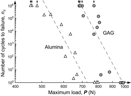
Damage maps for cementation bulk fracture in ceramic/ polycarbonate bilayers due to sliding-contact fatigue loading are reported (Fig. 4). It is apparent that more cycles, by several orders of magnitude, were required to initiate the flexural radial cracks in GAG/polycarbonate bilayers compared with the alumina/polycarbonate bilayers. ANOVA revealed a longer lifetime for graded GAG/polycarbonate than alumina/polycarbonate specimens [F(1,24) = 68.2, p < 0.001]. At the mean load of approximately 710 N, the mean lifetime of the graded GAG/polycarbonate specimens were estimated to be almost 400,000 cycles (95% confidence limits = 6.0 x 10⁴, 2.6 x 10⁶ cycles), while that of the alumina/polycarbonate specimens were estimated to be 12.3 cycles (95% confidence limits = 2.1, 73.1 cycles). In addition, there was a statistically similar slope relating load to lifetime for the 2 materials [F(1,24) = 0.3, p = 0.59], estimated to be a reduction, in either material, of approximately 100 cycles per 100 N increase (95% confidence limits = 103.8, 106.6 cycles). Analysis of these data suggests that, for a given load, graded GAG specimens will have a much longer fatigue lifespan than pure alumina specimens; similarly, for a given lifetime, graded GAG will tolerate a much greater load than homogeneous alumina specimens.
Figure 4.

Plot of number of cycles to failure, n F, as a function of maximum load, P, for cementation flexural radial fractures in GAG/polycarbonate (gray filled circles) and alumina/polycarbonate (open triangles) bilayers following sliding-contact fatigue. The fatigue loads P investigated are 682, 685, 701, 707, 773, 774, 793, 802, 808, 814, 879, 964, 979, and 982 N for GAG/polycarbonate bilayers, and 455, 460, 480, 510, 539, 588, 608, 634, 652, 660, 669, 777, 791, and 797 N for alumina/polycarbonate bilayers. Note: Arrows represent specimens that survived 1 million sliding-contact cycles (the fatigue endurance limit) at prescribed loads without radial fracture.
Discussion
This study investigated the resistance to flexural radial fracture of functionally graded GAG materials relative to homogeneous alumina under fatigue sliding-contact with a hard sphere on inclined (θ = 30°) ceramic/polycarbonate bilayers, analogous to tooth contact during mastication. Optical microscopy identified the damage sustained in alumina-based ceramic/polycarbonate systems: Flexural radial cracks initiated at the intaglio surface and propagated sideward and upward, resulting in catastrophic bulk fracture. These findings are consistent with clinical reports on alumina-based restorations where flexure-induced bulk fracture initiated from the cementation surface constitutes a major proportion of failures (Oden et al., 1998; Kokubo et al., 2009). Thus, despite the advantage of better translucency and a more natural tooth-like shade, alumina-based restorations have been replaced by the stronger zirconia. Here we demonstrate an effective way to improve the flexural strength of alumina by surface grading. Our fatigue study has shown that graded GAG exhibited much better resistance to long-term flexural fracture compared with homogeneous alumina. Composite beam theory predicts that the low-modulus surface in graded GAG is able to effectively dissipate the maximum flexural stress and redistribute it to the bulk of the material, away from the strength-limiting surface flaws (Zhang and Ma, 2009). In addition, the glass infiltrates the surface flaws of alumina, making GAG more immune to surface flaw population relative to homogeneous alumina. This argument is supported by the significantly higher Weibull modulus observed in graded GAG (7.7 ± 0.8) compared with that of alumina (5.2 ± 0.4) in fatigue-fractured specimen pools.
Clinical research and practice have also revealed that veneer chipping or fracture induced by occlusal surface cone fracture is often observed in all-ceramic restorations (Etman and Woolford, 2010), especially in strong ceramic-framework-supported systems, partly due to the rare occurrence of bulk fracture. The question then arises regarding the extent to which a glass-rich graded surface layer can withstand prolonged occlusion. Our results show that a high 682 N sliding load for 1 million cycles with a hard WC indenter managed to leave a smooth wear track only at the contact surface, indicating that GAG surfaces exhibit excellent resistance to occlusal-like sliding-contact damage. Contact mechanics analysis has shown that the low-modulus glassy surface was able to reduce the maximum tensile stress in the wake of the sliding indenter and transfer it into the bulk, suppressing the formation of the sliding-induced partial cone cracks (Giannakopoulos and Suresh, 1997; Suresh et al., 1999; Suresh, 2001; JW Kim et al., 2007, 2008, 2010; Zhang and Kim, 2010).
We present a new concept that improves the resistance of alumina to fatigue flexural damage while maintaining excellent wear resistance to occlusal contact damage by utilizing an alumina-glass functionally graded material. Since glass is used to infiltrate the accessible surfaces of alumina, a graded alumina-glass material possesses improved aesthetics relative to alumina. The low-hardness and modulus glassy surface can prevent excessive wear of the opposing dentition. The glass-rich intaglio surface offers a potential for acid etching and silanization, thus facilitating a resin cement bond (Zhang and Kim, 2009). With a simple staining technique, the graded alumina-glass material offers an aesthetic option for damage-resistant, monolithic crowns and potentially fixed partial dentures in the posterior regions.
Finally, we acknowledge that in the current GAG specimens, we gently polished away the surface residual glass layer to create a smooth, graded alumina-glass surface, facilitating direct comparison with the polished homogeneous alumina surface. Our ongoing fatigue studies of graded zirconia-glass structures with a thin (~20 µm) residual glass layer reveal excellent resistance to long-term sliding-contact fatigue damage. Neither spalling nor cracks have been observed on the residual glass/graded surfaces following 200 N sliding-contact for 1 million cycles in water. Since all of our tests were conducted on flat specimens, fatigue testing on anatomically correct crowns is next on our agenda.
Footnotes
This investigation was supported by Research Grant CMMI-0758530 (PI. Zhang) from the U.S. Division of Civil, Mechanical & Manufacturing Innovation, National Science Foundation and Research Grant 1R01 DE017925 (PI. Zhang) from the U.S. National Institute of Dental & Craniofacial Research, National Institutes of Health .
The authors declare no potential conflicts of interest with respect to the authorship and/or publication of this article.
Any mention of commercial products within this paper is for information only; it does not imply recommendation or endorsement by NIST.
References
- DeLong R, Douglas WH. (1983). Development of an artificial oral environment for the testing of dental restoratives: bi-axial force and movement control. J Dent Res 62:32-36 [DOI] [PubMed] [Google Scholar]
- Etman MK, Woolford MJ. (2010). Three-year clinical evaluation of two ceramic crown systems: a preliminary study. J Prosthet Dent 103:80-90 [DOI] [PubMed] [Google Scholar]
- Giannakopoulos AE, Suresh S. (1997). Indentation of solids with gradients in elastic properties: Part I. Point force. Int J Solids Struct 34:2357-2392 [Google Scholar]
- Heffernan MJ, Aquilino SA, Diaz-Arnold AM, Haselton DR, Stanford CM, Vargas MA. (2002). Relative translucency of six all-ceramic systems. Part I: Core materials. J Prosthet Dent 88:4-9 [PubMed] [Google Scholar]
- Hermann I, Bhowmick S, Zhang Y, Lawn BR. (2006). Competing fracture modes in brittle materials subject to concentrated cyclic loading in liquid environments: trilayer structures. J Mater Res 21:512-521 [Google Scholar]
- Huang M, Wang R, Thompson V, Rekow D, Soboyejo WO. (2007). Bioinspired design of dental multilayers. J Mater Sci Mater Med 18:57-64 [DOI] [PubMed] [Google Scholar]
- Jitcharoen J, Padture NP, Giannakopoulos AE, Suresh S. (1998). Hertzian-crack suppression in ceramics with elastic-modulus-graded surfaces. J Am Ceram Soc 81:2301-2308 [Google Scholar]
- Kelly JR. (1997). Ceramics in restorative and prosthetic dentistry. Annu Rev Mater Sci 27:443-468 [Google Scholar]
- Kelly JR. (1999). Clinically relevant approach to failure testing of all-ceramic restorations. J Prosthet Dent 81:652-661 [DOI] [PubMed] [Google Scholar]
- Kim B, Zhang Y, Pines M, Thompson VP. (2007). Fracture of porcelain-veneered structures in fatigue. J Dent Res 86:142-146 [DOI] [PubMed] [Google Scholar]
- Kim JH, Kim JW, Myoung SW, Pines M, Zhang Y. (2008). Damage maps for layered ceramics under simulated mastication. J Dent Res 87:671-675 [DOI] [PMC free article] [PubMed] [Google Scholar]
- Kim JW, Kim JH, Thompson VP, Zhang Y. (2007). Sliding contact fatigue damage in layered ceramic structures. J Dent Res 86:1046-1050 [DOI] [PMC free article] [PubMed] [Google Scholar]
- Kim JW, Kim JH, Janal MN, Zhang Y. (2008). Damage maps of veneered zirconia under simulated mastication. J Dent Res 87(12):1127-1132 [DOI] [PMC free article] [PubMed] [Google Scholar]
- Kim JW, Liu L, Zhang Y. (2010). Improving the resistance to sliding contact damage of zirconia using elastic gradients. J Biomed Mater Res B Appl Biomater 94:347-352 [DOI] [PMC free article] [PubMed] [Google Scholar]
- Kokubo Y, Sakurai S, Tsumita M, Ogawa T, Fukushima S. (2009). Clinical evaluation of Procera AllCeram crowns in Japanese patients: results after 5 years. J Oral Rehabil 36:786-791 [DOI] [PubMed] [Google Scholar]
- Oden A, Andersson M, Krystek-Ondracek I, Magnusson D. (1998). Five-year clinical evaluation of Procera AllCeram crowns. J Prosthet Dent 80:450-456 [DOI] [PubMed] [Google Scholar]
- Oliver WC, Pharr GM. (1992). An improved technique for determining hardness and elastic modulus using load and displacement sensing indentation experiments. J Mater Res 7:1564-1583 [Google Scholar]
- Suresh S. (2001). Graded materials for resistance to contact deformation and damage. Science 292:2447-2451 [DOI] [PubMed] [Google Scholar]
- Suresh S, Olsson M, Giannakopoulos AE, Padture NP, Jitcharoen J. (1999). Engineering the resistance to sliding-contact damage through controlled gradients in elastic properties at contact surfaces. Acta Materialia 47:3915-3926 [Google Scholar]
- Swain MV. (2009). Unstable cracking (chipping) of veneering porcelain on all-ceramic dental crowns and fixed partial dentures. Acta Biomater 5:1668-1677 [DOI] [PubMed] [Google Scholar]
- Zhang Y, Kim JW. (2009). Graded structures for damage resistant and aesthetic all-ceramic restorations. Dent Mater 25:781-790 [DOI] [PMC free article] [PubMed] [Google Scholar]
- Zhang Y, Kim JW. (2010). Graded zirconia glass for resistance to veneer fracture. J Dent Res 89:1057-1062 [DOI] [PMC free article] [PubMed] [Google Scholar]
- Zhang Y, Lawn B. (2004). Long-term strength of ceramics for biomedical applications. J Biomed Mater Res B Appl Biomater 69:166-172 [DOI] [PubMed] [Google Scholar]
- Zhang Y, Ma L. (2009). Optimization of ceramic strength using elastic gradients. Acta Materialia 57:2721-2729 [DOI] [PMC free article] [PubMed] [Google Scholar]
- Zhang Y, Chai H, Lawn BR. (2010). Graded structures for all-ceramic restorations. J Dent Res 89:417-421 [DOI] [PMC free article] [PubMed] [Google Scholar]


