Abstract
Carpal tunnel mechanics is relevant to our understanding of median nerve compression in the tunnel. The compliant characteristics of the tunnel strongly influence its mechanical environment. We investigated the distensibility of the carpal tunnel in response to tunnel pressure. A custom balloon device was designed to apply controlled pressure. Tunnel cross sections were obtained using magnetic resonance imaging (MRI) to derive the relationship between carpal tunnel pressure and morphological parameters at the hook of hamate. The results showed that the cross-sectional area (CSA) at the level of the hook of hamate increased, on average, by 9.2% and 14.8% at 100 mmHg and 200 mmHg, respectively. The increased CSA was attained by a shape change of the cross section, displaying increased circularity. The increase in CSA was mainly attributable to the increase of area in the carpal arch region formed by the transverse carpal ligament. The narrowing of the carpal arch width was associated with an increase in the carpal arch. We concluded that the carpal tunnel is compliant to accommodate physiological variations of the carpal tunnel pressure, and that the increase in tunnel CSA is achieved by increasing the circularity of the cross section.
Introduction
The carpal tunnel is a stable anatomical structure formed by the carpal bones interconnected by numerous ligaments. A rigid tunnel provides the benefits of stabilizing the structure to protect its contents (e.g., the median nerve) from external mechanical insults. However, an unyielding tunnel potentially predisposes the median nerve to compression within the tunnel. This unfavorable mechanical limitation is routinely resolved by transecting the transverse carpal ligament as the standard surgical treatment for carpal tunnel syndrome.
As an anatomical structure with a soft tissue component, the carpal tunnel demonstrates degrees of compliance and deformation. For example, the transverse carpal ligament has an increased palmar bowing for individuals with carpal tunnel syndrome (Monagle et al. 1999; Tsujii et al. 2009), which is presumably caused by elevated pressure in the tunnel and increased volume of the tunnel contents. In a cadaveric study, Li et al. showed that the carpal tunnel cross-sectional area (CSA) was increased by palmarly directed force on the transverse carpal ligament (Li et al. 2009). Xiu et al. also used cadaver hands to examine the compliance of the carpal arch and reported that the compliance in the inward direction was greater than that in the outward direction (Xiu et al. 2010). The CSA of the carpal tunnel changes with wrist flexion and extension (Skie et al. 1990; Yoshioka et al. 1993; Horch et al. 1997; Bower et al. 2006). Related to carpal tunnel deformation, Garcia-Elias et al. showed that the carpal arch width, measured between the trapezium and the hook of hamate, decreased when the wrist deviated from the neutral position (Garcia-Elias et al. 1992). In a search for a suitable animal model to study carpal tunnel syndrome, Tung et al. investigated carpal tunnel compliance and found that the dog had the most similar compliance to human (Tung et al. 2010).
Carpal tunnel mechanics has critical relevance to compression of the median nerve in the tunnel. The compliant characteristics of the tunnel strongly influence its internal mechanical environment. In this study, we investigated the distensibility of the carpal tunnel in response to the pressure inside it. We hypothesized that the carpal tunnel would be distensible with physiological pressure levels. Using cadaveric hands, we applied controlled carpal tunnel pressure through a custom balloon device and recorded the magnetic resonance (MR) images of the tunnel. We then derived the relationship between pressure and carpal tunnel morphology at the cross section of the hook of hamate. With these data, we tested the hypotheses that carpal tunnel pressure caused an increase in tunnel CSA and a change in cross-sectional shape.
Methods
Cadaveric specimens
8 fresh frozen cadaveric hand specimens (4 left, 4 right; 2 male, 6 female; mean age at death 47.4 yrs; range 42–55 yrs) were used. The specimens had no previously documented wrist injuries or surgeries. Each specimen was thawed overnight at room temperature and then dissected to expose the transverse carpal ligament and evacuate the carpal tunnel. The flexor tendons and median nerve were transected on the hand proximal to the wrist crease and pulled out of the tunnel at the mid-palm. The carpal tunnel boundaries were defined as the proximal and distal extents of the transverse carpal ligament through visual inspection and anatomical landmarks. A positioning device, consisting of a thermoplastic splint and a wood base was used to place the specimen palmar side up in the anatomically neutral position.
Pressure regulating device
A custom pressure device was designed to apply and regulate uniform pressure to the carpal tunnel boundaries (Fig. 1). The device consisted of a pneumatic side and a liquid side, separated by a diaphragm. The pressure of a noncompliant medical balloon (Advanced Polymers Inc., Salem, NH) was controlled using an inflation syringe (Cook Medical, Bloomington, IN). The device pressure was monitored using a digital pressure gauge with 0.25% full scale accuracy (CeComp Electronics, Libertyville, IL). The medical balloon was connected with a long catheter tube allowing all other device components to be located in a separate MRI control room. Prior to medical balloon inflation, all air was evacuated from the pressure device. The liquid side of the device was filled with an MRI contrast solution (Magnevist, Bayer Healthcare Pharmaceuticals, Berkeley, CA) at a ratio of 1 mL contrast to 500 mL water. The balloon was then inserted into the evacuated carpal tunnel and centered with the carpal tunnel length defined by the transverse carpal ligament. The specimen was then placed in the MRI scanner.
Figure 1.
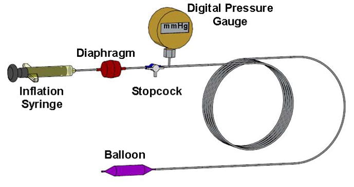
A custom balloon device to apply controlled pressure to the carpal tunnel.
Experimental procedures
Tunnel pressure ranged from 0 to 200 mmHg gauge pressure. MR images were collected at 0, 10, 20, 30, 40, 50, 75, 100, 125, 150, 175, and 200 mmHg. The balloon catheter system transmitted its pressure to the interior tunnel boundaries. Once the desired pressure level was reached, the pressure was maintained for the duration of imaging. Before beginning the MR sequence at each pressure, the specimen was given 2 mins for the CSA to change. After each pressure imaging sequence was completed, the balloon pressure was released to 0 mmHg and allowed to rest for 10 mins before the sequential pressure was reached and a new sequence initiated. Saline solution was applied to the transverse carpal ligament and surrounding area throughout the experiment to ensure that tunnel structures remained moist.
MR imaging
At each experimental pressure, MRI was performed using a 1.0 T imaging system (ONI Medical Systems Inc, Wilmington, MA). Axial images were obtained by 3D gradient echo (TR = 30 ms, TE = 8.9 ms, flip angle = 35°) with a 150 × 150 mm field of view and 260 × 192 matrix. The protocol was adjusted as follows: (1) the axial imaging plane was obliquely oriented ~13° (Mogk and Keir 2007) so that the slice plane was perpendicular to the dorsal side of the carpal tunnel (the sagittal scout images were used to determine the angle of oblique orientation for each specimen); (2) the slice thickness was set at 1 mm increments; and (3) the number of image slices was set between 28 and 38 for each specimen depending on the measured length of the carpal tunnel during dissection.
Data analyses
MR images were analyzed using ImageJ (v1.43, NIH). The hook of hamate level was identified using bony landmarks, where the trapezium and hook of hamate were most pronounced. The contrast agent within the balloon was manually traced to define the tunnel boundaries. The boundary outline was repeated 3 times for each pressure-specific image, and the measurements were averaged. For each outlined tunnel cross section, the software output the following morphological parameters: CSA (mm2); perimeter (mm); carpal arch width (mm); circularity; and aspect ratio. The carpal arch width was defined as the shortest distance between the hook of hamate and trapezium. Circularity was defined as 4πA/P2, where A was the CSA and P was the perimeter. The aspect ratio was calculated as the ratio of the major axis to the minor axis of the fitted ellipse. A value of 1.0 for circularity or aspect ratio indicated a perfect circle. Also, the total CSA was decomposed into A1 formed by bones on the dorsal side and A2 formed by the carpal arch of the TCL (Fig. 2).
Figure 2.
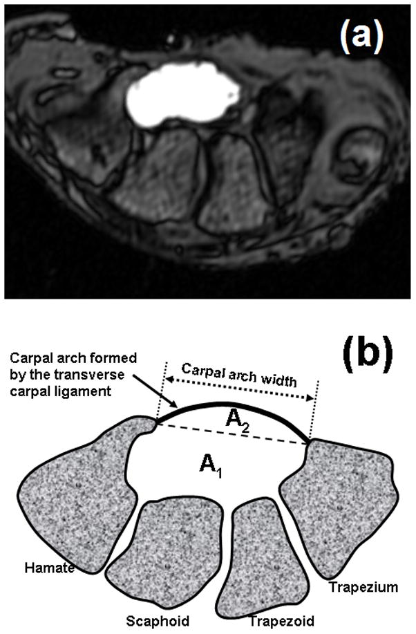
(a) A sample MRI at the hook of hamate with contrasted carpal tunnel cross section, and (b) a schematic drawing of the carpal tunnel cross section partitioned into A1 and A2.
Statistical Analyses
Repeated Measures ANOVAs were performed using SigmaStat (Systat Software, San Jose, CA) to determine the effect of pressure on the morphological parameters of the cross section at the hook of hamate level. As the data did not satisfy normality, Friedman Repeated Measures ANOVAs on Ranks were used. Tukey’s post hoc tests were used for pairwise comparisons. Linear and nonlinear regression analyses were also performed among the independent and dependent variables. A significance level of 0.05 was used.
Results
The initial area was 169.3 (SD 29.3) mm2. The areas formed by the bony portion (A1) and carpal arch (A2) were 134.9 (SD 19.2) mm2 and 34.4 (SD 12.6) mm2, respectively. The carpal tunnel areas (A, A1, A2) increased significantly with increasing pressure (p < 0.001, Fig. 3a). Pressure application at 100 and 200 mmHg resulted in a total area of 184.9 (SD 30.0) mm2 and 194.4 (SD 30.4) mm2, respectively, representing significant increases of 9.2% and 14.8% relative to the initial area (p < 0.05). The area compositions A1 and A2 at 200 mmHg were 146.7 (SD 17.6) mm2 and 47.7 (SD 14.8) mm2, respectively. This represents significant increases of 8.8% and 38.6% (p < 0.001) relative to their respective initial areas. A linear function sufficiently approximated the variation of total area with pressure changes (R2 > 0.97; Fig. 3a). Further analyses of the two area components (A1 and A2) showed that A1 increased linearly (R2 > 0.98; Fig. 3b) and A2 increased nonlinearly (R2 > 0.98; Fig. 3c) with pressure increases.
Figure 3.
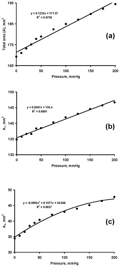
Carpal tunnel areas (mm2) at various pressure levels (mmHg). (a) Total area, A, (b) bony portion area, A1, (c) carpal arch area, A2
The carpal arch width was negatively correlated with carpal tunnel pressure (R = −0.95 (p < 0.05; Fig. 4), thus carpal tunnel pressure caused shortening of the carpal arch width. The initial arch width was 17.6 (SD 2.5) mm. The lowest arch width at 200 mmHg was 17.0 (SD 2.6) mm, a decrease of 3.4% with respect to the initial width.
Figure 4.
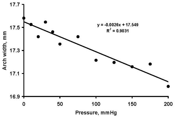
Carpal arch width (mm) at various pressure levels (mmHg)
The total carpal tunnel area and carpal arch width were negatively correlated with R=−0.94 (p < 0.05; Figure 5a). Similarly, the carpal arch width was negatively correlated with A1 (R=−0.95; p < 0.05; Fig. 5b) and A2 (R=−0.93; p < 0.05; Fig. 5c).
Figure 5.
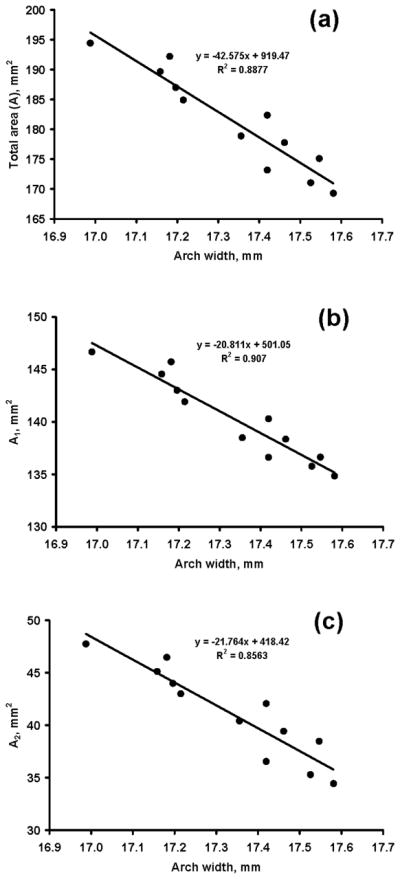
Carpal tunnel areas (mm2) at various arch widths (mm). (a) Total area, A, (b) bony portion area, A1, (c) carpal arch area, A2
The pressure application caused a change in carpal tunnel shape. Circularity increased significantly with increasing pressure (p < 0.001; Fig. 6a) while the aspect ratio decreased significantly (p < 0.001; Fig. 6b). Circularity changed from 0.72 (SD 0.04) at 0 mmHg to 0.79 (SD 0.02) at 200 mmHg, and the aspect ratio changed from 2.1 (SD 0.17) at 0 mmHg to 1.8 (SD 0.14) at 200 mmHg. The pressure also significantly affected the perimeter of the tunnel cross section (p < 0.05), but only one pair-wise comparison (200 vs. 0 mmHg, p < 0.05) was significant. The initial perimeter was 54.4 (SD 4.9) mm, and the maximal perimeter at the 200 mmHg was 55.3 (SD 4.3) mm, an increase of <1 mm (or less than < 2%).
Figure 6.
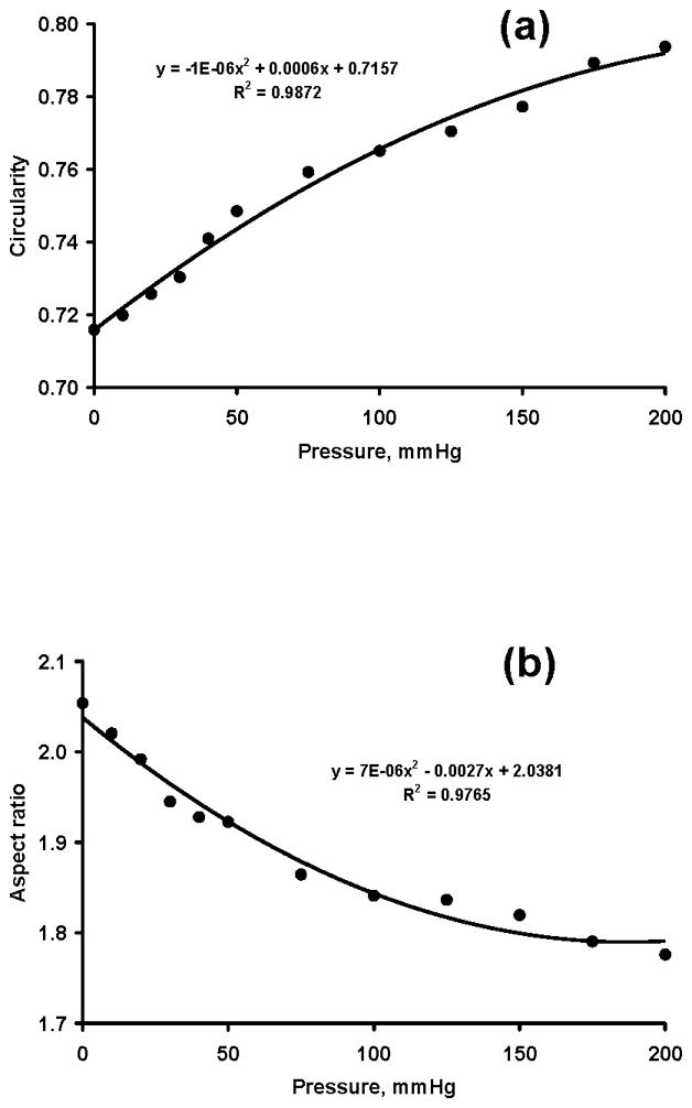
Carpal tunnel circularity (a) and aspect ratio (b) at various pressure levels (mmHg)
Discussion
We investigated the morphological changes of the carpal tunnel as a function of pressure variation in the tunnel. We confirmed our hypotheses that pressure application to the tunnel resulted in an increase in CSA and a change of cross-sectional shape. The increase of CSA and change in cross-sectional shape was a result of a decrease in carpal arch width.
A cadaveric hand model allowed us to vary carpal tunnel pressure and then examine the corresponding changes in CSA using MRI. In the past, MRI was used to quantify carpal tunnel morphology (Richman et al. 1987; Ablove et al. 1994). We developed a pressure regulating device including a balloon that inserted into the carpal tunnel. Also, the balloon was filled with MRI contrast fluid for accurate measurement of the CSA of the tunnel. Other methodological attempts were made to study carpal tunnel compliance. For example, Tung et al. used tapered metal rods to pass through the tunnel while measuring the resistance forces (Tung et al. 2010). Xiu et al. applied outward and inward forces on the carpal bones along the carpal arch width to derive the force-deformation relationship (Xiu et al. 2010). Garcia-Elias et al. applied compression force in the dorsopalmar direction to quantify the rigidity of the tunnel with and without the transverse carpal ligament (Garcia-Elias et al. 1989). Our technique mimicked some pathomechanical phenomena associated with pressure elevation inside the carpal tunnel (e.g. carpal tunnel syndrome). In a rabbit model, a balloon pressure technique was also used to compress the median nerve within the carpal tunnel for the understanding of median compression neuropathy (Diao et al. 2005).
Carpal tunnel pressure commonly reaches >200 mmHg in individuals with carpal tunnel syndrome (Gelberman et al. 1981; Okutsu et al. 1989). We found that the tunnel had considerable compliance to accommodate pressure variation. For example, our data indicated that the carpal tunnel CSA increased by ~9% and 15% at 100 mmHg and 200 mmHg, respectively, in comparison to the CSA at zero pressure. Although not reported, further analyses showed that the proximal tunnel at the pisiform level had greater compliance, increasing its CSA by ~14% and 21% at 100 mmHg and 200 mmHg, respectively, in comparison to its initial CSA. These findings suggest that carpal tunnel compliance is a desirable mechanical property, helping to accommodate the physiological changes in tunnel pressure and mitigating pressure buildup.
Increase in CSA was mainly attributed to the carpal arch formed by the transverse carpal ligament (A2 in Fig. 2b). For example, A2 increased by~25% and 39% at 100 mmHg and 200 mmHg, respectively, in comparison to its initial area. In contrast, the bony portion of the tunnel (A1) only increased by ~5% and 9% at 100 mmHg and 200 mmHg, respectively. These results agree well with our previous study that, when a palmarly directed force was applied to the transverse carpal ligament, the increase in area was attributable to the ligament formed carpal arch (Li et al. 2009). Our findings also coincide with in vivo data after carpal tunnel release, showing that, for the increase of 88 mm2 of the tunnel’s total CSA, 93% of the increase was due to the carpal arch (Kato et al. 1994).
We found that the tunnel perimeter remained relatively constant when pressures were applied. This is consistent with our previous finding that the transverse carpal ligament did not elongate with up to a 200 N force applied palmarly on the ligament (Li et al. 2009). However, an increase in tunnel pressure resulted in a decrease in carpal arch width, which allowed the formation of an increasingly greater carpal arch. Using a geometric model, Li et al. showed that the increase in carpal arch area was sensitive to the narrowing of the carpal arch width (Li et al. 2009). For example, a decrease of 0.2 mm in the arch width caused an increase of 16.1 mm2 in arch area (Li et al. 2009). In our study, 200 mmHg caused a decrease of 0.6 mm in carpal arch width and an increase of 13.3 mm2 in arch area. The amount of area increase was smaller than the model prediction, which may be explained by the model assumption of no initial arch formation. Our results also corroborate in vivo observations that the carpal arch width decreases when the wrist deviated from the neutral position (Garcia-Elias et al. 1992). Wrist deviation away from the neutral position leads to elevated carpal tunnel pressure (Gelberman et al. 1981; Okutsu et al. 1989; Weiss et al. 1995), and our results showed that an increase in tunnel pressure is associated with carpal arch narrowing.
The circularity and aspect ratio of the cross section were positively and negatively correlated with tunnel pressure, respectively. This means that the higher the pressure, the rounder the tunnel’s cross section. The circularity changed from 0.72 at 0 mmHg to 0.79 at 200 mmHg, and the aspect ratio changed from 2.05 at 0 mmHg to 1.78 at 200 mmHg. The change in cross-sectional shape explains the change in CSA even though the perimeter remains unchanged. It is a geometrical theorem that the shape of maximum area for a given perimeter is a circle, which has a circularity and aspect ratio of 1. The carpal tunnel cross section is far from circular with an initial circularity of 0.72 and an initial aspect ratio of 2.05. This non-circularity provides an opportunity for increasing the tunnel’s CSA by geometrically increasing its circularity or decreasing its aspect ratio. Further research is needed to determine to what extent this geometric manipulation could be achieved for this particular anatomical structure.
We acknowledge several limitations in this study. First, the viscoelastic behavior of the carpal tunnel structure was not considered. In our previous study, the carpal arch portion did not appear to show deformation affected by loading history (Li et al. 2009). However, this study maintained each pressure application for ~4 mins to finish the scanning at each pressure level. This loading duration was longer than our previous study, and its viscoelasticity effects warrant future investigation. Second, the balloon’s CSA had to be larger than that of the carpal tunnel to transmit the balloon pressure to the tunnel. Wrinkles within the balloon were present leading to possible error associated with the calculation of the tunnel’s CSA. To mitigate the human error associated with manually selecting the tunnel boundary using ImageJ software, each CSA was traced 3 times, and the calculated values were averaged. This averaged value was used in all further comparisons. Special attention was paid to set up the pressure device to ensure that air bubbles were eliminated from the liquid side, but a few occasions occurred when small air bubbles showed on the MR images. These artifacts were easily identifiable, and the balloon boundary was traced along the convex hull of the contrast agent. To minimize inconsistencies in outlining the tunnel boundary, the same person analyzed all images. Unlike the common image segmentation on anatomical structures, our procedures to identify the tunnel area with contrast agent proved to be unambiguous and reliable.
Supplementary Material
Acknowledgments
This study was supported by the National Institutes of Health (NIAMS R03AR054510).
Contributor Information
Zong-Ming Li, Email: liz4@ccf.org.
Tamara L. Masters, Email: mastert@ccf.org.
Tracy A. Mondello, Email: mondelt@ccf.org.
References
- Ablove RH, Peimer CA, Diao E, Oliverio R, Kuhn JP. Morphologic changes following endoscopic and two-portal subcutaneous carpal tunnel release. J Hand Surg [Am] 1994;19:821–826. doi: 10.1016/0363-5023(94)90194-5. [DOI] [PubMed] [Google Scholar]
- Bower JA, Stanisz GJ, Keir PJ. An MRI evaluation of carpal tunnel dimensions in healthy wrists: Implications for carpal tunnel syndrome. Clin Biomech (Bristol, Avon) 2006;21:816–825. doi: 10.1016/j.clinbiomech.2006.04.008. [DOI] [PubMed] [Google Scholar]
- Diao E, Shao F, Liebenberg E, Rempel D, Lotz JC. Carpal tunnel pressure alters median nerve function in a dose-dependent manner: a rabbit model for carpal tunnel syndrome. J Orthop Res. 2005;23:218–223. doi: 10.1016/j.orthres.2004.05.014. [DOI] [PubMed] [Google Scholar]
- Garcia-Elias M, An KN, Cooney WP, 3rd, Linscheid RL, Chao EY. Stability of the transverse carpal arch: an experimental study. J Hand Surg [Am] 1989;14:277–282. doi: 10.1016/0363-5023(89)90021-x. [DOI] [PubMed] [Google Scholar]
- Garcia-Elias M, Sanchez-Freijo JM, Salo JM, Lluch AL. Dynamic changes of the transverse carpal arch during flexion-extension of the wrist: effects of sectioning the transverse carpal ligament. J Hand Surg [Am] 1992;17:1017–1019. doi: 10.1016/s0363-5023(09)91049-8. [DOI] [PubMed] [Google Scholar]
- Gelberman RH, Hergenroeder PT, Hargens AR, Lundborg GN, Akeson WH. The carpal tunnel syndrome. A study of carpal canal pressures. J Bone Joint Surg Am. 1981;63:380–383. [PubMed] [Google Scholar]
- Horch RE, Allmann KH, Laubenberger J, Langer M, Stark GB. Median nerve compression can be detected by magnetic resonance imaging of the carpal tunnel. Neurosurgery. 1997;41:76–82. doi: 10.1097/00006123-199707000-00016. discussion 82–73. [DOI] [PubMed] [Google Scholar]
- Kato T, Kuroshima N, Okutsu I, Ninomiya S. Effects of endoscopic release of the transverse carpal ligament on carpal canal volume. J Hand Surg [Am] 1994;19:416–419. doi: 10.1016/0363-5023(94)90055-8. [DOI] [PubMed] [Google Scholar]
- Li ZM, Tang J, Chakan M, Kaz R. Carpal tunnel expansion by palmarly directed forces to the transverse carpal ligament. J Biomech Eng. 2009;131:081011. doi: 10.1115/1.3148469. [DOI] [PMC free article] [PubMed] [Google Scholar]
- Mogk JP, Keir PJ. Evaluation of the carpal tunnel based on 3-D reconstruction from MRI. J Biomech. 2007;40:2222–2229. doi: 10.1016/j.jbiomech.2006.10.033. [DOI] [PubMed] [Google Scholar]
- Monagle K, Dai G, Chu A, Burnham RS, Snyder RE. Quantitative MR imaging of carpal tunnel syndrome. AJR American Journal of Roentgenology. 1999;172:1581–1586. doi: 10.2214/ajr.172.6.10350293. [DOI] [PubMed] [Google Scholar]
- Okutsu I, Ninomiya S, Hamanaka I, Kuroshima N, Inanami H. Measurement of pressure in the carpal canal before and after endoscopic management of carpal tunnel syndrome. J Bone Joint Surg Am. 1989;71:679–683. [PubMed] [Google Scholar]
- Richman JA, Gelberman RH, Rydevik BL, Gylys-Morin VM, Hajek PC, Sartoris DJ. Carpal tunnel volume determination by magnetic resonance imaging three-dimensional reconstruction. J Hand Surg [Am] 1987;12:712–717. doi: 10.1016/s0363-5023(87)80054-0. [DOI] [PubMed] [Google Scholar]
- Skie M, Zeiss J, Ebraheim NA, Jackson WT. Carpal tunnel changes and median nerve compression during wrist flexion and extension seen by magnetic resonance imaging. J Hand Surg [Am] 1990;15:934–939. doi: 10.1016/0363-5023(90)90019-n. [DOI] [PubMed] [Google Scholar]
- Tsujii M, Hirata H, Morita A, Uchida A. Palmar bowing of the flexor retinaculum on wrist MRI correlates with subjective reports of pain in carpal tunnel syndrome. J Magn Reson Imaging. 2009;29:1102–1105. doi: 10.1002/jmri.21459. [DOI] [PubMed] [Google Scholar]
- Tung WL, Zhao C, Yoshii Y, Su FC, An KN, Amadio PC. Comparative study of carpal tunnel compliance in the human, dog, rabbit, and rat. J Orthop Res. 2010;28:652–656. doi: 10.1002/jor.21037. [DOI] [PMC free article] [PubMed] [Google Scholar]
- Weiss ND, Gordon L, Bloom T, So Y, Rempel DM. Position of the wrist associated with the lowest carpal-tunnel pressure: implications for splint design. J Bone Joint Surg Am. 1995;77:1695–1699. doi: 10.2106/00004623-199511000-00008. [DOI] [PubMed] [Google Scholar]
- Xiu KH, Kim JH, Li ZM. Biomechanics of the transverse carpal arch under carpal bone loading. Clin Biomech (Bristol, Avon) 2010;25:776–780. doi: 10.1016/j.clinbiomech.2010.05.011. [DOI] [PMC free article] [PubMed] [Google Scholar]
- Yoshioka S, Okuda Y, Tamai K, Hirasawa Y, Koda Y. Changes in carpal tunnel shape during wrist joint motion. MRI evaluation of normal volunteers. J Hand Surg [Br] 1993;18:620–623. doi: 10.1016/0266-7681(93)90018-b. [DOI] [PubMed] [Google Scholar]
Associated Data
This section collects any data citations, data availability statements, or supplementary materials included in this article.


