Abstract
We present a maskless micropatterning system that utilizes a fluorescence microscope with programmable X-Y stage and dry film photoresist to realize feature sizes in the sub-millimeter range (40–700 μm). The method allows for flexible in-house maskless photolithography without a dedicated microfabrication facility and is well-suited for rapid prototyping of microfluidic channels, scaffold templates for protein/cell patterning or optically-guided cell encapsulation for biomedical applications.
Keywords: Maskless photolithography, Microfluidics, Cell patterning, Dry film photoresist
1 Introduction
Photolithography-based microfabrication is the standard technique in various applications including circuit printing and microfluidic chip design. In its classic implementation, the technique employs a photosensitive material where geometric patterns are generated by selectively blocking light with a user-specified spatial mask after appropriate preparation in a clean-room facility with specialized equipment. In the last decade, microfabrication has permeated substantially into biomedical research for better control of protein/cell patterning (Singhvi et al. 1994; Folch and Toner 2000). Such biomedical laboratories do not necessarily have dedicated microfabrication facilities and trained personnel.
Since the introduction of soft lithography (easy creation of geometric patterns using poly-dimethylsiloxane (Whitesides et al. 2001)), much progress has been made in localizing lithographic technologies to the home laboratory. Predominantly, a photolithographic step using a wet photoresist capable of relatively deep features, e.g. SU-8, is part of the process, unless alternative, less popular micromachining methods are employed (Xia et al. 1996; Entcheva and Bien 2005). Thus, in most cases, access to spin-coating and mask-aligning equipment is necessary at a minimum.
Recently, Vulto et al. demonstrated that dry film photoresists (DFP) offer reliable thickness uniformity, low cost, predictable ‘on or off’ responses to exposure and require less overhead in terms of support facilities compared to the classically used SU-8 (Vulto et al. 2005). Guijt and Breadmore illustrated further simplification of the DFP-based rapid prototyping process by eliminating the need for a mask (Guijt and Breadmore 2008). Instead, their proof-of-principle setup focused collimated LED light onto a DFP-bound substrate driven by a linear syringe pump. Yoshida et al. extended the concept of localized light delivery to photopolymerizable gels using tight spatial control for a drug release application (Yoshida et al. 2006). All these recent developments can facilitate the use of microfabrication by dedicated biomedical research laboratories without the need for access to specialized equipment.
Here, we present a highly accessible technique that allows for the rapid prototyping of patterns using DFP in any laboratory that houses an epifluorescent microscope equipped with a motorized stage. We characterize feature size determinants, develop an algorithm for generation of patterns with arbitrary connectivity and demonstrate the versatility and utility of the technique in examples including the fabrication of microfluidic channels and cell patterning.
2 Experimental
2.1 Maskless microscope-based DFP patterning
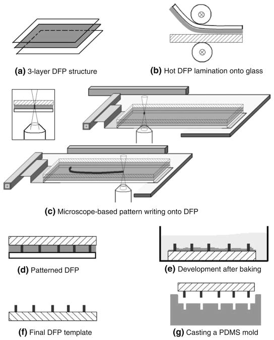
Negative DFP Ordyl SY 330 (ElgaEurope, Italy) was used here because of its potential for resulting in relatively high-depth features (30 μm per layer), excellent planarity, threshold-like response to UV irradiation (at a dose of at least 75 mJ/cm2) and ease of use (Vulto et al. 2005). Figure 1 depicts the steps involved in our M3: Microscope-based Maskless Micropatterning approach. First, the protective polyester layer was peeled off and the DFP was placed, photoresist side down, on a glass coverslide. The slide was run through a hot laminator at ~70°C at 0.5 m/min. Up to three DFP layers (for a total of 90 μm thickness) can be stacked and laminated similarly, but the MYLAR® boPET layer must be removed from the previously laminated layer before the next one is stacked.
Fig. 1.
M3 Process: (a) Dry film photoresist (DFP) Ordyl SY330, consisting of MYLAR backing, negative photoresist, and protective layer (top-to-bottom). (b) Lamination of DFP onto a glass coverslip with protective layer peeled off. (c) Pattern creation using microscope stage movement and exposure to UV light (365 nm) via the objective (inset). Fine feature resolution requires a low NA objective lens. (d) Exposed pattern. (e) Washing with developer after 20 min baking at 100°C. (f) Finished template slide. (g) Cast PDMS mold from template
An inverted epifluorescence Nikon TE2000-U microscope was used to generate the desired pattern. The laminated slide was exposed to UV light (365 nm filter) using a standard Xenon light source with an optical light guide connected to the microscope. Nikon S Fluor 40× or 20× objective lenses (NA=0.75) were used, sometimes in conjunction with either a neutral density filter for control of the exposure dose or a 1/8 in. pinhole in the back focal plane of the objective to further restrict the illuminated spot and control spatial resolution.
The generation of the pattern was realized with a programmable motorized microscope stage (Prior Optiscan II ES107; ±5 μm repeatability along both axes), which moved the DFP in X-Y with respect to the stationary objective (Fig. 1(c)). This stage has a maximum movement area of 115 mm×77 mm with a minimum step size of 1 μm. Custom software in C++ (compiled in Qt, a Trolltech labs/Nokia Inc. C++ GUI development software) was used for computer control of the stage via a COM port. The desired pattern was presented as a sorted list of x-y coordinates. The software interprets the file and instructs the stage to move along the designated path. The software can also introduce timing constraints and can control feature width by varying the speed of the stage. For further details on control of the microscope stage, see Electronic Supplementary Information (part I).
2.2 DFP development and soft lithography
The irradiated DFP slide was baked for 20 min at 100°C. After cooling to room temperature, the MYLAR® boPET layer was carefully peeled off. The slide was immersed in the Ordyl BMR DEVELOPER C-3 for 6 to 10 min for a film of 30 μm with constant agitation and then rinsed in ethanol for 1 min.
A 10:1 ratio of PDMS polymer base and curing agent (Dow Corning® Sylgard® 184 Silicone Elastomer Kit) was mixed thoroughly and degassed under vacuum. The PDMS mixture was poured to cover the entire slide uniformly and was then cured for 2 h at 65°C. After cooling, the PDMS cast was carefully peeled from the master slide. Cardiac fibroblast culture was prepared as described previously (Entcheva and Bien 2003; Entcheva and Bien 2009) and cells were plated on fibronectin-coated scaffolds.
3 Results and discussion
3.1 Micropatterning feature characterization
In-plane feature size is directly related to the exposure. Smaller features are realized by reducing the exposure by either faster stage movement velocities or by attenuating light intensity using neutral density filters. Figure 2(c, d) were generated based on experimental data. Stage speeds of 500, 1,000, 1,500, 2,000, 2,500 μm/sec were tested at illumination intensities of 100%, 63%, 50% and 25% achieved by the use of neutral density filters. Ten (10) measurements were made per combination with demonstrated variability of 10%. Spline interpolation was applied for feature sizes at intermediate values to construct the graphs in Fig. 2(c, d). The numerical aperture (NA) of the objective also can be used to control light intensity and feature size. Higher magnification, lower NA objectives can produce the smallest feature size (see illustration in Fig. 2(e)). A more aggressive approach to limit light delivery may be used where the numerical aperture of the lens is artificially reduced through the use of a pinhole aperture at the back focal plane of the objective (in this case, the effective NA with a pinhole was approximately 0.1). Feature sizes as small as 40 μm can be achieved in this manner (Fig. 2(a)) whereas full-aperture operation at our tested stage velocities resulted in feature sizes between 250 and 700 μm (Fig. 2(b)). Finally, the tight tolerance associated with DFP’s flatness (Vulto et al. 2005) allows for stacking of layers with highly predictable feature heights (30 μm in Fig. 2(a) and 60 μm in Fig. 2(b)).
Fig. 2.
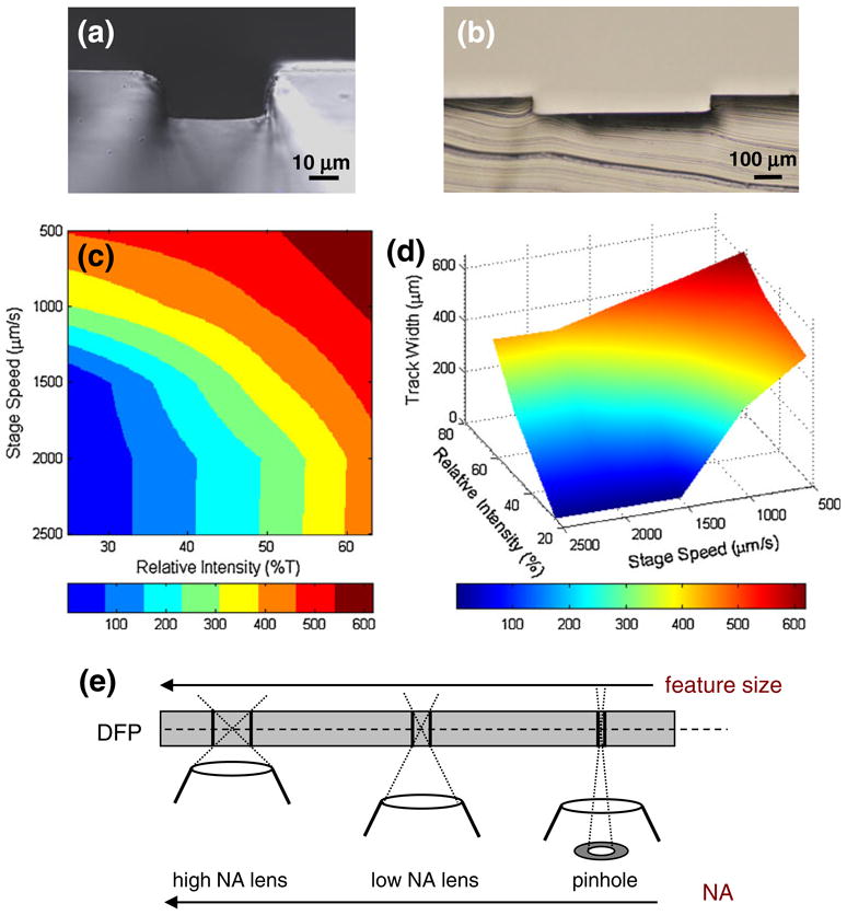
Feature characterization: (a) Single thickness DFP (30 μm channel height) exposed with a pinhole aperture at a linear stage speed of 250 μm/s. (b) Double thickness DFP (60 μm channel height) exposed with objective lens at aperture at linear stage speed of 500 μm/s. (c, d) Experimental feature characterization: in-plane feature width as a function of stage speed and relative UV intensity (as modulated by neutral density filters). (e) Schematic illustration of the effect of objective’s numerical aperture (NA) on feature size produced in the DFP, where lower NA results in smaller feature size; extreme NA reduction can be obtained by using a pinhole aperture in conjunction with the lens (see text for details)
3.2 Pattern realization
3.2.1 Connected patterns
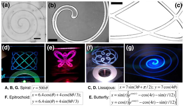
The continuous (shutterless) light delivery used in this study is well suited for generating connected patterns of varying complexity. We illustrate this with several analytical curves realized in the DFP and shown post-development (Fig. 3), including a spiral, a figure of Lissajous, a butterfly and an epitrochoid. The approach is reasonably fast—for example, a path length of 15 cm can be drawn in under 5 min.
Fig. 3.
Example patterns: Analytical curves after DFP development and their equations are shown: (a, b & g) spiral; (c, d) Lissajous; (e) butterfly; (f) epitrochoid. Scale bars are: (a) 3,000 μm, (b) 500 μm, (c) 1,000 μm
3.2.2 Disconnected patterns
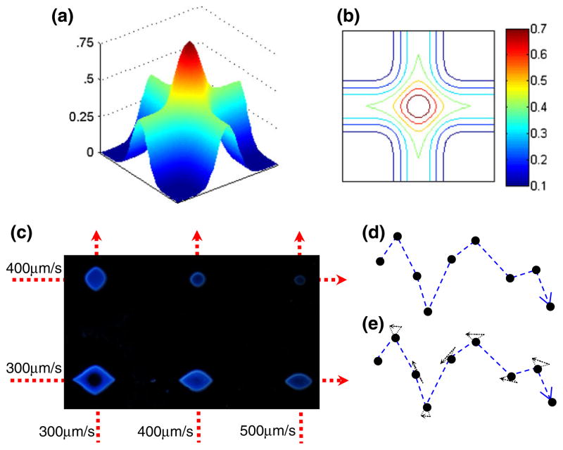
For simplicity and affordability, in this design, we have avoided the use of a shutter, which can help generate disconnected patterns. Instead, we can broaden the system’s use to allow for the creation of disconnected patterns with algorithmic methods from computational geometry and graph theory (Flood 1956; Lin and Kernighan 1973; Rosenkrantz et al. 1977; Bentley 1992). Since the DFP shows a threshold-like response to UV dose, two exposures at one location, each at subthreshold level (but ≥50% of the dose threshold), will successfully create an isolated point only at this location (Fig. 4(a, b)). Figure 4c confirms experimentally the generation of such isolated points upon double exposure (the intersection of two lines written at sub-threshold intensity). Interestingly, anisotropic islands result when unequal speeds are used during the two separate exposures along different axes. Further work is needed for characterization of the isolated points created with multiple subthreshold exposures.
Fig. 4.
Shutterless generation of disconnected patterns via multiple subthreshold exposures: (a) Expected UV dose distribution and (b) equal-dose isolines after two axis-aligned exposures. (c) Experimental DFP island generation by shutterless micropatterning (double exposure) using different combinations of velocities for the x- and y-axes, as indicated, in pinhole aperture mode. Reflectance microscopy image of the obtained DFP islands is shown; scale bar is 100 μm. (d, e) Algorithmic implementation of the method: (d) The input is a set of isolated points in 2D and (e) polygonized by connecting the points in their left-to-right order. Each path segment is extended slightly in each direction. Each pair of extended segments is joined to form a small triangle at each of the original input points. This path is used to expose the DFP and generate the input point set exactly
We show that it is possible to use this exposure superposition principle to create arbitrary disconnected patterns without a need for shuttering the light, i.e. during continuous exposure, see Fig. 4(d, e) and Table 1. The principle of exposure superposition is used in conjunction with “Traveling Salesman” tour construction (Bentley 1992) and improvements heuristics (Lin and Kernighan 1973) to plan a path of exposure that ensures supra-threshold UV dosage occurring only at the desired location despite the continuous exposure of the DFP. The method for double-exposing desired points in the DFP in such a way that the resulting points exactly match the desired set of points (i.e., there are no missing or extra points) is covered in more detail in the Electronic Supplementary Information (part II).
Table 1.
Summary of M3 patterning capabilities
| Pattern | Restrictions | Algorithm | UV exposure |
|---|---|---|---|
| Connected | Eulerian connectivity | Build a doubly-connected edge list (De Berg et al. 2008) and create an Eulerian circuit with Fleury’s algorithm (Fleury 1883) | ET for one exposure |
| Disconnected | Isolated points | Modification of a TSP approximating path | for n exposures |
| Composite | None known | Handle the disconnected components first and then expose connected components afterwards | ET for one exposure along connected components for two exposures at disconnected locations |
ET is the exposure threshold that induces feature creation in the photoresist (75 mJ/cm2 ) and δ is an arbitrarily small positive value (e.g. 0.01–0.10) to ensure that exposure saturation is achieved
3.3 Selected applications
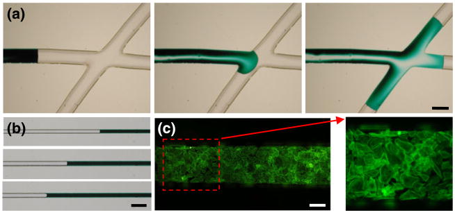
Miniaturization of multicomponent systems is the essence of creating new enabling lab-on-a-chip technologies. Designing and prototyping such systems within the confines of a biologically oriented laboratory that is furnished with typical equipment further reduces the effort needed for coordinating among multiple specialized facilities. Although DFPs were originally designed for aiding in the production of printed circuit boards (Vulto et al. 2005), we show immediate applicability in laboratories working in the biomedical sciences, particularly those involved with microfluidics or the patterning of biomolecules and cells. Here, DFP was used to fabricate microfluidic channels measuring from a few tens of microns (Fig. 5(b)) to several hundred microns (Fig. 5(a)). Obtained features are commensurate with cell dimensions and suitable for biological applications, including cell patterning (Fig. 5(c)).
Fig. 5.
Example applications: (a) Channels on the order of hundreds of microns made in full aperture mode, sealed with a glass side, serving as conduits for fluid transfer. Actual channel width depicted is 440 μm. (b) Channels on the order of tens of microns made in pinhole aperture mode can also be used in microfluidics applications. Actual channel width depicted is 50 μm. (c) Primary cardiac fibroblasts grown on a fibronectin-coated PDMS mold and stained for cytoskeletal actin. Scale bar is 100 μm
Even though the proposed M3 process is serial in nature, a complex shape can be transferred within minutes. Connected patterns are created in a straightforward manner with continuous movement of the stage, while disconnected patterns require further considerations (as discussed above; see Supplemental Information for details). In contrast to a recently proposed technique where the input pattern is read out using a shutter and rasterized traversal of the photoresist (Park et al. 2009), our technique uses a dry film photoresist and avoids the use of a shutter by traveling only over the regions of the photoresist that contain features to be exposed. This apparent increase in complexity is contained entirely within the software and therefore introduces no additional financial expense. For simple patterns, e.g. lines, a very straightforward control of the stage can be achieved by command-line input via the HyperTerminal using manufacturer-supplied commands for the particular microscope stage; an example is provided in the Electronic Supplementary Information (part I). The ability to generate a desired pattern directly using a standard bio-laboratory microscope while bypassing the use of specialized mask-aligning equipment offers not only the possibility to pattern DFP as discussed here, but also to introduce spatial optical control in a photopolymerizable cell-encapsulating gel or to project any dynamic patterns onto live cells, e.g. using light-sensitive ion channels (Boyden et al. 2005).
4 Conclusions
We have demonstrated maskless micropatterning to be possible in a biological laboratory equipped with a standard fluorescence microscope system. By controlling the numerical aperture, stage speed and the intensity of the delivered light, a wide range of feature sizes (40 μm–700 μm) relevant for biological applications can be realized. Feature depth is controlled by varying the number of layers of the dry film photoresist. Although the method is best suited for connected patterns, a shutter-based design or multiple exposure-based traversing, as described here, can create any arbitrary pattern.
Supplementary Material
Acknowledgments
We thank Nicolas Glade (University Joseph Fourier, Grenoble, France) for assistance with the methodology for film exposure and developing and ElgaEurope for the donation of the resist. This work was partially supported by a grant from the National Institutes of Health (GM071558) and the National Science Foundation (CCF-0729019).
Footnotes
Electronic supplementary material The online version of this article (doi:10.1007/s10544-010-9506-2) contains supplementary material, which is available to authorized users.
Contributor Information
Steven Y. Leigh, Department of Biomedical Engineering, Stony Brook University, HSC T18-030, Stony Brook, NY 11794-8181, USA
Aashay Tattu, Department of Biomedical Engineering, Stony Brook University, HSC T18-030, Stony Brook, NY 11794-8181, USA.
Joseph S. B. Mitchell, Department of Applied Mathematics and Statistics, Stony Brook University, Stony Brook, NY 11794-3600, USA
Emilia Entcheva, Email: emilia.entcheva@sunysb.edu, Department of Biomedical Engineering, Stony Brook University, HSC T18-030, Stony Brook, NY 11794-8181, USA. Department of Physiology and Biophysics, Stony Brook University, Stony Brook, NY 11794, USA.
References
- Bentley JJ. Fast algorithms for geometric traveling salesman problems. INFORMS J Comput. 1992;4(4):387. [Google Scholar]
- Boyden ES, Zhang F, et al. Millisecond-timescale, genetically targeted optical control of neural activity. Nat Neurosci. 2005;8(9):1263–1268. doi: 10.1038/nn1525. [DOI] [PubMed] [Google Scholar]
- De Berg M, Cheong O, et al. Computational geometry: algorithms and applications. Springer; New York: 2008. [Google Scholar]
- Entcheva E, Bien H. Tension development and nuclear eccentricity in topographically controlled cardiac syncytium. Biomed Micro-devices. 2003;5(2):163–168. [Google Scholar]
- Entcheva E, Bien H. Acoustic micromachining of three-dimensional surfaces for biological applications. Lab Chip. 2005;5(2):179–183. doi: 10.1039/b409478f. [DOI] [PubMed] [Google Scholar]
- Entcheva E, Bien H. Mechanical and spatial determinants of cytoskeletal geodesic dome formation in cardiac fibroblasts. Integr Biol (Camb) 2009;1(2):212–219. doi: 10.1039/b818874b. [DOI] [PMC free article] [PubMed] [Google Scholar]
- Fleury M. Deux problèmes de géometrie de situation. J Math Élém. 1883:257–261. [Google Scholar]
- Flood MM. The traveling-salesman problem. Oper Res. 1956:61–75. [Google Scholar]
- Folch A, Toner M. Microengineering of cellular interactions. Annu Rev Biomed Eng. 2000;2:227–256. doi: 10.1146/annurev.bioeng.2.1.227. [DOI] [PubMed] [Google Scholar]
- Guijt RM, Breadmore MC. Maskless photolithography using UV LEDs. Lab Chip. 2008;8(8):1402–1404. doi: 10.1039/b800465j. [DOI] [PubMed] [Google Scholar]
- Lin S, Kernighan BW. An effective heuristic algorithm for the traveling-salesman problem. Oper Res. 1973:498–516. [Google Scholar]
- Park ES, Jang D, et al. Maskless optical microscope lithography system. Rev Sci Instrum. 2009;80 doi: 10.1063/1.3266965. [DOI] [PubMed] [Google Scholar]
- Rosenkrantz DJ, Stearns RE, et al. An analysis of several heuristics for the traveling salesman problem. SIAM J Comput. 1977;6(3):563–581. [Google Scholar]
- Singhvi R, Kumar A, et al. Engineering cell-shape and function. Science. 1994;264(5159):696–698. doi: 10.1126/science.8171320. [DOI] [PubMed] [Google Scholar]
- Vulto P, Glade N, et al. Microfluidic channel fabrication in dry film resist for production and prototyping of hybrid chips. Lab Chip. 2005;5(2):158–162. doi: 10.1039/b411885e. [DOI] [PubMed] [Google Scholar]
- Whitesides GM, Ostuni E, et al. Soft lithography in biology and biochemistry. Annu Rev Biomed Eng. 2001;3:335–373. doi: 10.1146/annurev.bioeng.3.1.335. [DOI] [PubMed] [Google Scholar]
- Xia YN, Tien J, et al. Non-photolithographic methods for fabrication of elastomeric stamps for use in microcontact printing. Langmuir. 1996;12(16):4033–4038. [Google Scholar]
- Yoshida R, Omata K, et al. Maskless microfabrication of thermosensitive gels using a microscope and application to a controlled release microchip. Lab Chip. 2006;6(10):1384–1386. doi: 10.1039/b606620h. [DOI] [PubMed] [Google Scholar]
Associated Data
This section collects any data citations, data availability statements, or supplementary materials included in this article.


