Abstract
We present a new method for simulating two-phase flows in complex geometries, taking into account contact lines separating immiscible incompressible components. We combine the diffuse domain method for solving PDEs in complex geometries with the diffuse-interface (phase-field) method for simulating multiphase flows. In this approach, the complex geometry is described implicitly by introducing a new phase-field variable, which is a smooth approximation of the characteristic function of the complex domain. The fluid and component concentration equations are reformulated and solved in larger regular domain with the boundary conditions being implicitly modeled using source terms. The method is straightforward to implement using standard software packages; we use adaptive finite elements here. We present numerical examples demonstrating the effectiveness of the algorithm. We simulate multiphase flow in a driven cavity on an extended domain and find very good agreement with results obtained by solving the equations and boundary conditions in the original domain. We then consider successively more complex geometries and simulate a droplet sliding down a rippled ramp in 2D and 3D, a droplet flowing through a Y-junction in a microfluidic network and finally chaotic mixing in a droplet flowing through a winding, serpentine channel. The latter example actually incorporates two different diffuse domains: one describes the evolving droplet where mixing occurs while the other describes the channel.
Keywords: diffuse domain, diffuse interface, phase field, complex domain, fluid-structure interaction, Navier-Stokes, Cahn-Hilliard, finite element, contact angle, chaotic mixing
1 Introduction
Many applications of multiphase flows in engineering and the physical and biological sciences involve complex flow geometries, interfacial physics and the motion of contact lines separating immiscible components at solid boundaries These are highly challenging problems for numerical simulation. For example, special treatment of the contact line is needed to regularize the stress singularity. Further, standard methods require the discretization of the complicated domain, which rules out coarse-scale discretizations and efficient multi-level solutions. In addition the automatic generation of proper three-dimensional meshes for complex geometries remains a challenge. In many applications the complex geometry might even evolve in time which would require a new discretization at each time step.
Because of the importance of solving multiphase flows in complex geometries, a variety of different numerical techniques have been developed. In the fictitious domain approach (e.g., see Glowinsky, Pan, Hesla, Joseph, and Periaux (2001); Yu, Thien-Phan, Fan, and Tanner (2002); Glowinksi, Pan, and Periaux (2006); Yu and Shao (2007); Pao, Pan, Glowinski, and Joseph (2009)), the complex geometry is embedded in a larger, simpler domain, the discretization is performed in this larger domain and Lagrange multipliers are used to enforce the correct boundary conditions at solid/fluid interfaces. Other approaches in this direction enlarge the set of test functions to account for the boundary conditions. Examples include the extended finite element method (e.g., Duarte, Babuska, and Oden (2000); Melenk and Babuska (1996); Oden, Duarte, and Zienkiewicz (1998)), the immersed interface method (e.g., Gong, Li, and Li (2008); Li, Lin, and Wu (2003)). Other approaches include boundary integral methods (e.g., Mayo (1984); Kropinski (1999); Biros, Ying, and Zorin (2003)) which explicitly incorporate the boundary conditions in the reformulated equations, front-tracking (e.g., Tryggvason, Buner, Esmaeeli, Juric, Al-Rawahi, Tauber, Han, Nas, and Jan (2001); Al-Rawahi and Tryggvason (2002, 2004); Muradoglu and Kayaalp (2006)) and arbitrary Eulerian-Lagrangian methods (e.g., Udaykumar, Kan, Shyy, and Tran-Son-Tay (1997); Hu, Patankar, and Zhu (2001); Udaykumar, Mittal, Rampunggoon, and Khanna (2001); Uzgoren, Sim, and Shyy (2009)) which utilize a separate Lagrangian mesh to track the complex boundary and either smear the boundary conditions across several mesh points, or explicitly enforce the boundary conditions on the Lagrangian mesh which cuts across the Eulerian mesh using body forces or modified discretizations. Other methods along these lines include level-set, immersed interface, ghost-fluid and cut-cell methods (e.g., Zhao, Merriman, Osher, and Wang (1998); Balaras (2004); Kirkpatrick, Armfield, and Kent (2003); Tseng and Ferziger (2003); Gilmanov and Sotiropoulos (2005); Chung (2006); Xu and Wang (2006); Choi, Oberoi, Edwards, and Rosati (2007); Gao, Ingram, Causon, and Mingham (2007); Lin (2007); Gilmanov and Acharya (2008); Mittal, Dong, Bozkurttas, Najjar, Vargas, and von Loebbecke (2007); Deng, Shao, and Ren (2006); Borazjani, Ge, and Sotiropoulos (2008); Shinn, Goodwin, and Vanka (2009); de Zelicourt, Ge, Wang, Sotiropoulos, Gilmanov, and Yoganathan (2009)). Most of this work does not deal directly with multiple-phase contact lines as the classical equations have a stress singularity (e.g., Davis (2002)). To remove the singularity, various regularizations have introduced including the use of a slip velocity, microscopic interactions, a precursor film or a diffuse interface (e.g., see de Gennes (1985); Kalliadasis and Chang (1994); Oron, Davis, and Bankoff (1997); Bertozzi (1998); Jacqmin (1999); Xie, Koshizuka, and Oka (2007)). Current implementations primarily use body-fitted meshes.
All methods, discussed thus far, require nonstandard tools and are therefore typically not available in standard finite element or finite difference software packages. The complex geometry is either given explicitly through a surface triangulation or implicitly as a level set function. Li, Lowengrub, Rätz, and Voigt (2009), and later Yu, Chen, and Thornton (submitted 2009), used a phase-field function (see Wang and Zhou (2004)) to represent the complex domain and developed methods for solving partial differential equations (PDEs) in complex geometries with Dirichlet, Neumann and Robin boundary conditions. This work builds on previous research (Kockelkoren, Levine, and Rappel, 2003; Levine and Rappel, 2005; Fenton, Cherry, Karma, and Rappel, 2005; Bueno-Orovio, Perez-Garcia, and Fenton, 2006; Bueno-Orovio and Perez-Garcia, 2006). In addition, Li, Lowengrub, Rätz, and Voigt (2009) incorporated moving domains. In this approach the complex geometry was embedded into a larger regular domain and a phase-field function was used to smoothly approximate the characteristic function of the original domain. Accordingly, the sharp boundary of the original domain was replaced by a narrow diffuse interface layer. The original PDE was reformulated on the larger, regular domain with additional source terms that approximate the boundary conditions. The reformulated PDE was shown to converge to the original PDE and boundary conditions as the width of the diffuse interface layer tends to zero.
The diffuse domain approach does not require any modification of standard finite element or finite difference software and thus offers a simple way to solve general equations in complex geometries. The diffuse domain approach has recently been extended to account for coupling among PDEs defined in a bulk domain and on a surface and was used to investigate the evolution of multiphase flows with soluble surfactants (Teigen, Li, Lowengrub, Wang, and Voigt, 2010; Teigen, Song, Lowengrub, and Voigt, 2010).
In this paper, we apply the diffuse domain approach to simulate two-phase flows in complex geometries taking into account contact lines separating immiscible components. In particular, we combine the diffuse domain approach for solving PDEs in complex geometries with the diffuse-interface (phase-field) method for simulating multiphase flows. In the context of fluid flows, however, the pressure and incompressibility constraint require additional consideration. Here, we develop a reformulation of the incompressibility equation and a new, diffuse interface formulation of the Navier-Stokes equations that enable accurate and efficient simulations to be performed.
In the diffuse interface method for multiphase flows, sharp interfaces are replaced by narrow transition layers and smooth auxiliary phase-field functions are introduced to model the concentrations of the components. The diffuse interface method has a long history in the theory of phase transformations dating back to van der Waals and has been used recently to simulate multiphase flows including drop coalescence and break-up, electrowetting and viscoelasticity. By incorporating a wall potential, the diffuse interface method has also been used to regularize the stress singularity at contact lines and simulate contact line motion in fluid structure interactions. See the reviews Anderson, McFadden, and Wheeler (1998); Emmerich (2008); Singer-Loginova and Singer (2008). Here, we use the diffuse interface approach to develop an implicit formulation of the contact line condition at solid boundaries.
The new diffuse-domain method for multiphase flows is straightforward to implement using either finite difference or finite element discretizations; we follow the latter here. The method differs from previous implementations of diffuse interface (phase-field) methods for interactions among multiphase flows and simple-shaped solid structures (e.g. Jacqmin (1999); Gránásy, Pusztai, Saylor, and Warren (2007); Villanueva and Amberg (2006); Do-Quang and Amberg (2009); Zhou, Yue, Feng, Ollivier-Gooch, and Hu (2010)), in that the geometry and boundary conditions are described implicitly. Accordingly, the fluid and component concentration equations are reformulated and solved in a larger regular domain with the boundary conditions being modeled using source terms rather than being implemented directly at the boundary of a body-fitted mesh as in the references above. This allows the use of arbitrary geometries with standard mesh elements, although local mesh refinement is typically needed to increase accuracy near the domain boundary and the interfaces separating the different fluid components.
We present numerical examples demonstrating the effectiveness of taking into account contact lines separating immiscible components. the diffuse domain method for simulating multiphase flows in complex geometries. We simulate multiphase flow in a driven cavity on an extended domain and find very good agreement with results obtained by solving the equations and boundary conditions in the original domain. We then consider successively more complex geometries and simulate a droplet sliding down a rippled ramp in 2D and 3D, a droplet flowing through a Y-junction in a microfluidic network and finally chaotic mixing in a droplet flowing through a winding, serpentine channel. The latter example actually incorporates two different diffuse domains: one describes the evolving droplet where mixing occurs while the other describes the channel.
The outline of the paper is as follows. In section 2, we present the classical mathematical models of multiphase flow and the diffuse domain formulation. In section 3, the discretizations of the equations are presented. In section 4, the numerical results are given. Finally, in section 5, conclusions are drawn and future research directions are discussed.
2 Mathematical model
In this section, we present the diffuse domain formulation of two-phase flows in an arbitrary geometry using the diffuse-interface multiphase flow model. We begin by recalling the classical sharp and diffuse interface models.
2.1 Classical models
In two-phase flow, the Navier-Stokes equations equations are
| (1) |
| (2) |
where Ωi, for i = 1, 2 denotes the domain and ρi, ui, pi, νi, Fi are the density, velocity, pressure, viscosity and body force in domain Ωi respectively. Across the interface Σ separating the domains, the following jump conditions hold:
| (3) |
where [f]Σ = f1 − f2 denotes the jump in f across Σ, I is the identity tensor, D = (∇u+∇uT), n is the normal vector to Σ pointing into Ω2, σ is the surface tension, κ is the total curvature (positive for a sphere), and ∇Σ = (I−nn)∇ is the surface gradient. Let Ω̃ = Ω1∪Ω2 and let Γ =∂Ω̃ denote the boundary of the fluid domain. If Γ is a solid boundary, the no-slip condition is imposed. In the event that the interface Σ intersects a solid boundary, another boundary condition needs to be provided. For an interface in equilibrium, a contact angle condition (Young’s law) may be posed
| (4) |
where θ is the (equilibrium) contact angle, σiS is the interfacial energy between the solid and component i. The contact angle characterizes the wettability of the surface with θ = 0 denoting complete wetting. However, in the dynamical setting with the no-slip condition, the force needed to move a contact line is infinite making it necessary to regularize the system (e.g., Davis (2002)). Numerous methods have been implemented to regularize the problem including introducing a slip velocity, microscopic interactions, a precursor film or a diffuse interface (e.g., see de Gennes (1985); Kalliadasis and Chang (1994); Oron, Davis, and Bankoff (1997); Bertozzi (1998); Jacqmin (1999)) Here, we follow the diffuse interface approach.
In the diffuse interface approach for mixtures of two immiscible, incompressible fluids with the same density, which we set to 1 for simplicity, the Navier-Stokes-Cahn-Hilliard equations (NSCH) govern the evolution (e.g., see the reviews Anderson, McFadden, and Wheeler (1998); Emmerich (2008); Singer-Loginova and Singer (2008)). This is also known as Model H (Hohenberg and Halperin, 1977) and is given by
| (5) |
| (6) |
| (7) |
| (8) |
in the domain Ω̃. Here u, p, c and μ are the (mass-averaged) velocity, pressure, phase field (concentration) and chemical potential, respectively. The function W(c) is a double well potential, here we use W = 1/4(c2 −1)2 such that c ≈ 1 in Ω1 and ≈ −1 in Ω2. The function M(c) is a mobility, here we use M(c) = γW(c), where γ is a constant mobility coefficent. Furthermore ν = ν (c) and F = F(c) are interpolations of the viscosity and body force, e.g. ν(c) = ν1(c+1)/2+ν2(c − 1)/2. The parameter σ̃ is a scaled surface tension which is related to the physical surface tension by . An extension to variable densities can be found in Lowengrub and Truskinovsky (1998). Assuming that Γ = ∂Ω̃ is a solid boundary, the conditions at Γ may be posed as
| (9) |
| (10) |
| (11) |
where g is the velocity of Γ and n is the outward normal to Ω̃. Assuming Γ is closed, the boundary velocity needs to satisfy 0 = ∫Γ g · n dS. Further, as in Eq. (4), θ is the equilibrium contact angle. Eq. (11) naturally arises by incorporating a wall free energy in the diffuse interface formulation, see (Jacqmin, 1999; Villanueva and Amberg, 2006; Gránásy, Pusztai, Saylor, and Warren, 2007; Do-Quang and Amberg, 2009) for details. We also refer the reader to Zhou, Yue, Feng, Ollivier-Gooch, and Hu (2010) for recent 3D applications in Newtonian and viscoelastic flows.
2.2 Diffuse domain formulation
We next reformulate the NSCH system (5)–(11) using the diffuse domain method (Li, Lowengrub, Rätz, and Voigt, 2009) in a larger, regular domain Ω which contains Ω̃. A phase field function ϕ is introduced to approximate the characteristic function of the domain Ω̃: ϕ ≈ 1 in Ω̃ and ϕ ≈ 0 in Ω/Ω̃ and the solid boundary Γ, which may be time dependent, is described implicitly through ϕ, e.g., Γ(t) = {x|ϕ(x, t) = 1/2}. For example, we may take ϕ(x, t) = 0.5(1 − tanh(3r(x, t)/εϕ)) where r(x, t) is the signed distance from a point x to Γ and εϕ is the thickness of the solid boundary transition layer. Here, we take εϕ = ε unless otherwise stated. Alternatively, ϕ may be determined as the solution of an advective Cahn-Hilliard equation (Teigen, Li, Lowengrub, Wang, and Voigt, 2010).
Following the general formulation given in Li, Lowengrub, Rätz, and Voigt (2009), the NSCH system may be rewritten to implicitly embed the boundary conditions in the equations to yield the diffuse domain NSCH system (DDNSCH)
| (12) |
| (13) |
| (14) |
| (15) |
in Ω, with boundary conditions u = 0, n · ∇c = n · ∇μ = 0 on ∂Ω; the system is not sensitive to the boundary conditions imposed on ∂Ω. We have additionally assumed that the solid boundary velocity g may extended off Γ. The terms BCu, BCμ and BCc impose the internal boundary conditions on the implicitly defined solid boundary. Different formulations of the internal boundary conditions are provided by Li, Lowengrub, Rätz, and Voigt (2009). We use
| (16) |
where β is a scaling factor, to enforce the usual no slip condition u = 0,
| (17) |
to enforce the wetting condition n · , and
| (18) |
In Li, Lowengrub, Rätz, and Voigt (2009) β = 1, but in fact other choices are possible ranging from β ~ 1 to εϕ, as can be seen from the asymptotic analysis in Li, Lowengrub, Rätz, and Voigt (2009). We have implemented other boundary approximations from Li, Lowengrub, Rätz, and Voigt (2009) for BCu and BCc and found that other choices yield similar results. Interestingly, we found that if one uses ϕ∇ · (νD) instead of ∇ · (νϕD) for the viscous term, the results are again similar. However, using ∇(ϕp) instead of ϕ∇p does not work.
We also remark that the form of BCc given above assumes that the boundary condition h := n ·∇c is extended off Γ as a constant in the normal direction (Li, Lowengrub, Rätz, and Voigt, 2009). Since , it is not clear that this is indeed the case because the interface layer in c may signficantly overlap the boundary layer around Γ, described by a rapid transition in ϕ. However, numerical tests suggest that this form of BCc works well. Indeed, if one assumes that the presence of the interface layer in c does not affect the (inner) asymptotic expansions in the boundary layer around Γ, e.g. εϕ<< ε, then one may conclude that c is constant in the transition layer across Γ, which is sufficient to show convergence to the original boundary condition on Γ (Li, Lowengrub, Rätz, and Voigt, 2009).
If we assume that ϕ is advected by the velocity u
| (19) |
noting that u|Γ = g, then Eqs. (12) and (14) may be simplified to
| (20) |
| (21) |
These simplifications should not be used if ϕ satisfies the advective Cahn-Hilliard equation.
We next provide a brief explanation for the form of Eq. (13). To begin, write the weak form of ∇ · u = 0 in Ω̃ as
| (22) |
where ψ is an appropriate test function and n is the outward normal to Ω̃. Let χ be the characteristic function of Ω̃ (i.e. χ(x, t) = 1 if x ∈ Ω̃ and χ = 0 otherwise). Then, we can extend Eq. (22) to Ω by
| (23) |
where we have used that |∇χ| = δΓ the surface delta function. Integrating the left hand side of Eq. (23) by parts we get
| (24) |
since the boundary terms vanish on ∂Ω due to χ. Taking χ ≈ ϕ, n = − ∇ϕ/|∇ϕ| and asking that the above holds for arbitrary ψ gives Eq. (13).
The DDNSCH system thus consists of Eqs. (12) or (20), (13), (14) or (21), and (15). The advantage of this system is that it is posed on a regular domain and can be solved by any standard approach. The sharp interface limit ε → 0 is an interesting question because of the underlying singularity in the sharp interface model (in the absence of a slip velocity or other regularizing terms). If the interface does not intersect solid boundaries, then the classical sharp interface equations (1)–(3) are obtained (e.g., Lowengrub and Truskinovsky (1998)). If the sharp interface intersects the solid boundary, then the question is still open. Our numerical results are inconclusive in this case as we find that the rate of convergence in ε decreases as ε → 0.
3 Finite element discretization
For the numerical solution of the DDNSCH system we adapt existing algorithms for the NSCH equations, e.g. Feng (2006); Villanueva and Amberg (2006); Kay and Welford (2007).
Let Th be a triangulation of the domain Ω of mesh size h and let be a quasi-uniform partition of [0,T] of mesh size . Of course, adaptive time steps may also be used. We define the discrete time derivative dtνm := (νm − vm−1)/τ. Furthermore, for a non-negative integer r, let Pr(K) denote the space of polynomials of degree less than or equal to r on a triangle or tetrahedron K ∈ Th. We introduce the finite element spaces
| (25) |
| (26) |
| (27) |
and denote by Vh = (Vh)d the space of vector test functions in dimension d.
The diffuse domain Navier-Stokes and Cahn-Hilliard systems are solved seperately in an operator splitting manner. For both systems we use an implicit Euler time stepping algorithm. Higher order algorithms may also be used. At every time step we first solve the Navier-Stokes system and then solve the Cahn-Hilliard equations. If ϕ needs to be evolved, then ϕ is updated before u and c.
3.1 Diffuse domain Navier-Stokes system
The finite element approximation for the diffuse domain Navier-Stokes equations (in simplified form) is as follows. Find (um, pm) ∈ Vh × Mh such that for all (v,q) ∈ Vh × Mh
| (28) |
| (29) |
where (f, g) denotes the L2(Ω) inner product. Also note that the term ϕ∇p has been replaced by ∇(ϕp)−p∇ϕ. This approach has two benefits. First, it does not involve any derivatives of p. Second, combined with the incompressibility condition in Eq. (13), this choice maintains the saddle point structure of the original Navier-Stokes system. This was found to be essential for the solvability of the discrete system. To show the saddle point structure, in 2D for simplicity, we denote the ansatz functions by vi and qi, respectively, and write the resulting 2D system as
| (30) |
where
with . The terms By, Cy and by are defined analogously. Hence one can see that the condition [Bx By] = −[Cx Cy]T, which is satisfied for the original Navier-Stokes equations, is still fulfilled in the diffuse domain formulation.
3.2 Diffuse domain Cahn-Hilliard system
In the case of a stationary domain (ϕm = ϕ), the finite element approximation for the convective diffuse domain Cahn-Hilliard equations (in simplified form) is as follows. Find (Cm,μm) ∈ Yh × Yh such that for all (ψ, ξ) ∈ Yh × Yh
| (31) |
| (32) |
The second term of Eq. (31) can be rewritten using integration by parts and Eq. (13) to give
In this form we obtain volume conservation of cm on Ω1 which follows by setting ψ = 1: ∫Ω ϕcm dx = const. Furthermore, we linearize the derivative of the double well potential W′(cm) by a Taylor expansion of order one:
to obtain a linear system but keeping the non-linearity (semi)-implicit. To obtain conservation when the domain is moving, the original form of the phase field equation (14) should be used and Eq. (31) should be replaced with
| (33) |
from which conservation, ∫Ω ϕmcm dx = const, clearly follows.
3.3 Numerical treatment
The adaptive finite element toolbox AMDiS (Vey and Voigt, 2007) is used for discretization. In 2D the polynomial degree was chosen to be two for u and one for p, c and μ. The linearized system was solved using the direct unsymmetric multifrontal method (UMFPACK, Davis (2004)).
In 3D, the linear systems become too large and a different approach is needed. We also use linear basis functions for u and a simple projection method to solve the Navier-Stokes equations. In this first order method proposed in Chorin (1968) momentum and incompressibility equation are solved successively. The scheme is given by
| (34) |
| (35) |
| (36) |
In Eq. (34), D* = ∇u* + ∇u*T. We use BiCGStab(ell) to solve Eq. (34) and the Cahn-Hilliard system and a CG method to solve Eq. (35). To ensure the well-posedness of the equations for all calculations ϕ is replaced by ϕ + δ, see Rätz and Voigt (2006); Li, Lowengrub, Rätz, and Voigt (2009) for details. Here, we use δ = 10−6.
3.4 Adaptivity
Adaptive meshes are indispensible for providing a high spatial resolution along the internal boundary Γ, described implicitly by ϕ, and the fluid-fluid interfaces described implicitly by c. For local mesh adaptation, we use a L2-like error indicator based on a jump residual (e.g., Verfürth (1996); Vey and Voigt (2007)) for ϕ and c to maintain approximately 5 grid points across the transition layers. Although we did not find it necessary to do here, additional mesh refinement can be used to increase local resolution of the flow field (e.g., velocity gradients, etc.).
4 Numerical examples
4.1 Driven cavity flow
First, we simulate flow in a driven cavity to compare the results of the DDNSCH system on an extended domain with the NSCH model on the physical domain. Parameters are as in Boyer (2002), the viscosity is ν = 0.002, the mobility coefficient is γ = 0.001, the surface tension is σ̃ = 0, the contact angle is θ = 90° and the interface thickness is εϕ = ε = 0.01. The scaling factor is β = ν. We solve the NSCH equations (5)–(8) on the physical domain Ω̃ = [0,1.0]2, with boundary conditions (9)–(11), and compare the results with the DDNSCH equations (12)–(15) on the enlarged domain Ω=[−0.25,1.25]2. At the upper boundary the velocity in horizontal direction is imposed to be
All remaining boundary velocities are set to be zero.
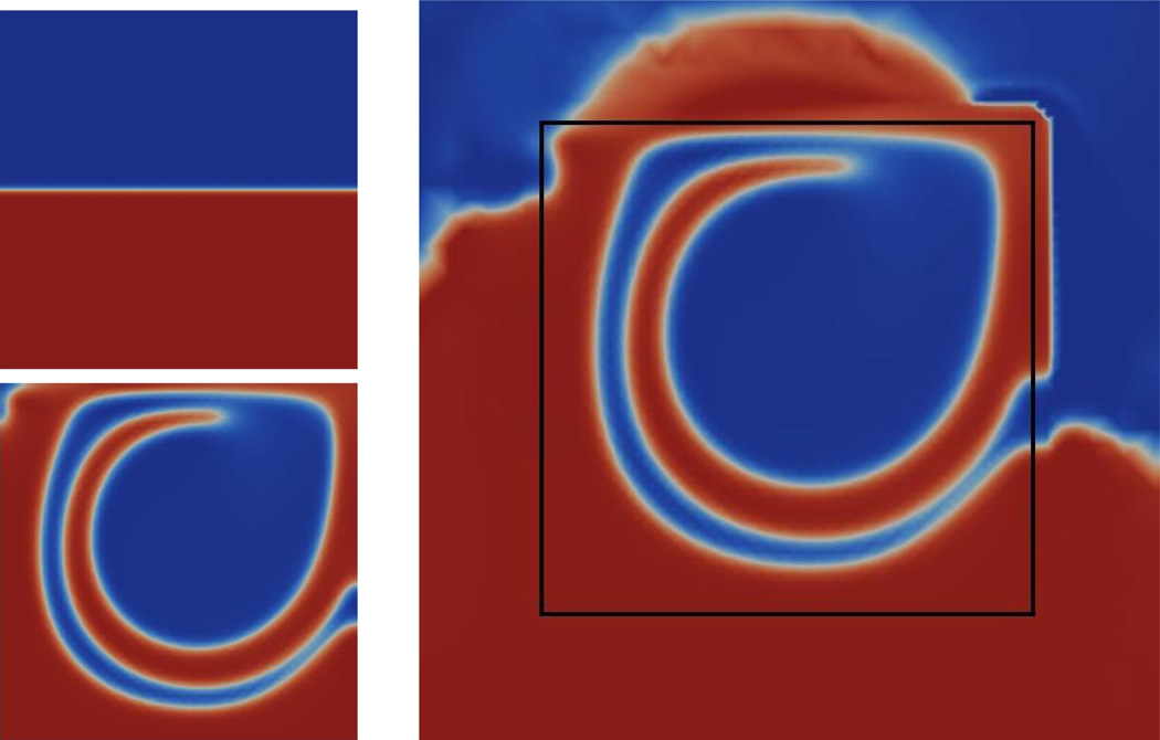
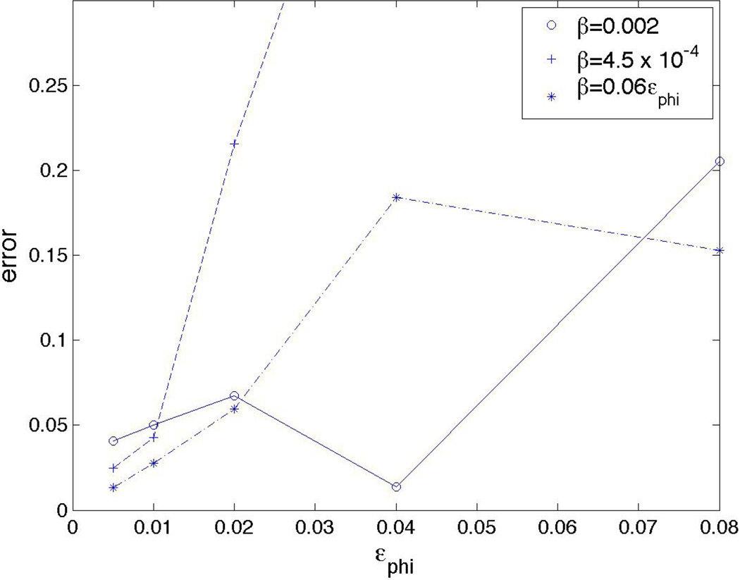
Figure 1 shows the phase-field function c for the initial condition (flat interface) and at time t = 15 obtained from the NSCH system (left) and the DDNSCH system (right) with a box indicating the location of the physical domain Ω̃. There is good quantitative agreement between the models. Next we investigate the εϕ → 0 limit, holding ε = 0.01 fixed. In Figure 2 we present the difference ‖c(T)DD − c(T)phys domain‖L2 as a function of εϕ for different choices of β. All choices of β generally show the error decreasing as a function of εϕ, for εϕ sufficiently small, but that the best results are obtained taking β ~ εϕ. Note that for larger εϕ the transition layers in c and ϕ interact and non-uniform behavior is observed.
Figure 1.
Flow in a driven cavity. Initial condition (top left) and solution on the physical domain (bottom left) and a diffuse domain (right). The black rectangle marks the position of the physical boundary modeled by ϕ = 1/2. Color online.
Figure 2.
L2 error for different values of boundary layer thickness εϕ between the NSCH solution in the physical domain and the DDNSCH solution in the extended domain for the flow in a driven cavity from Figure 1, with ε = 0.01 fixed.
4.2 Y-shaped channel
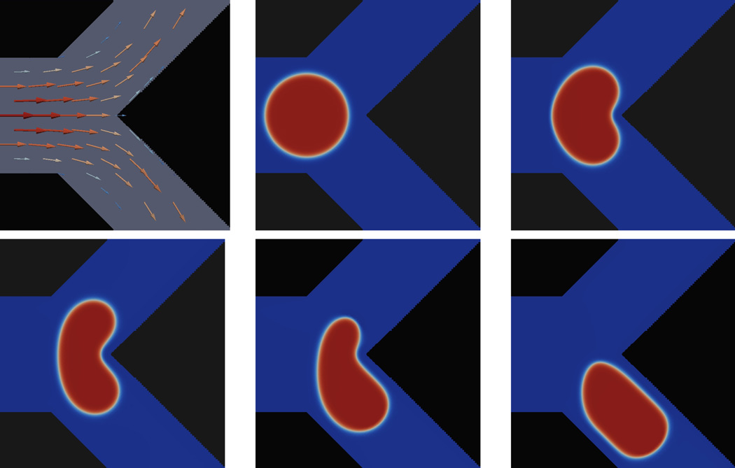
We next consider a drop flowing through a Y-shaped channel. See Figure 3, the channel has inlet diameter 0.5. The outlet branches have a smaller diameter 0.354. At the inflow boundary (left), we prescribe a parabolic velocity profile. The maximum velocity is 4.0. An analogous profile, oriented in the (1,1) and (1,−1) directions for the upper and lower branches, is specified for the two outflow conditions at the two branches.
Figure 3.
Flow field in the channel (top left) and snapshots of a droplet with contact angle 180° flowing through it at times t = 0, 0.2, 0.4, 0.6, and 0.8. The area {ϕ < 0.5} is colored black. Color online.
We place the droplet of diameter 0.36 with center slightly below the middle of the channel. On the walls of the channel, we impose the non-wetting boundary condition θ = 180°. The channel is embedded in an extended domain Ω = [0,1]2. The region ϕ < 0.5 is colored black. The viscosity is ν = 0.1, the surface tension is σ̃ = 1.0, the mobility is γ = 20.0 and the interface thickness is εϕ = ε = 0.01. Figure 3 shows the flow field and the movement of the droplet. As the droplet flows through the channel, it is deformed by the Y-junction and elongates to fit through the lower branch.
Figure 4 shows the same simulation but with a contact angle θ = 90°. The droplet now adheres to the wall at the Y-junction and splits into two, roughly hemispherical parts that then exit each branch of the channel. Increasing the surface tension σ̃ = 10.0, still keeping the contact angle θ = 90°, changes the evolution as seen in Figure 5. Now after adhering to the wall, the droplet remains intact and exits the channel through the lower branch.
Figure 4.
The evolution of a droplet flowing through a channel with the same parameters as in Figure 3 except with contact angle θ = 90° at times t = 0.3, 0.6 and 0.9. Color online.
Figure 5.
The evolution of a droplet flowing through a channel with the same parameters as in Figure 4 except with a larger surface tension σ̃ = 10.0 at times t = 0.3, 0.9, and 1.23. Color online.
4.3 Sliding droplets
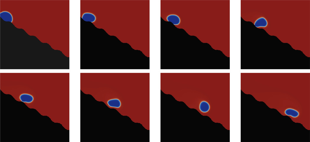
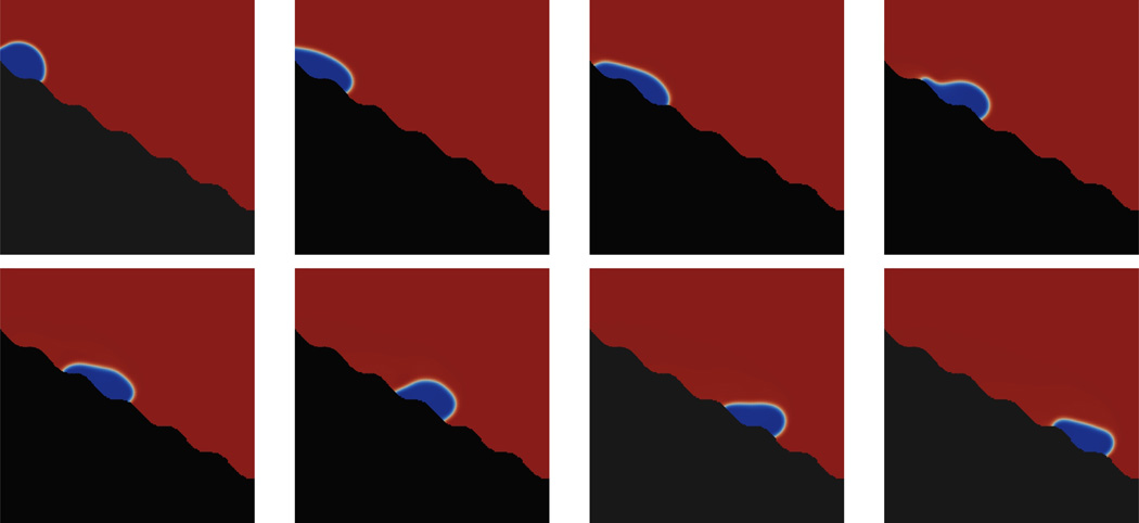
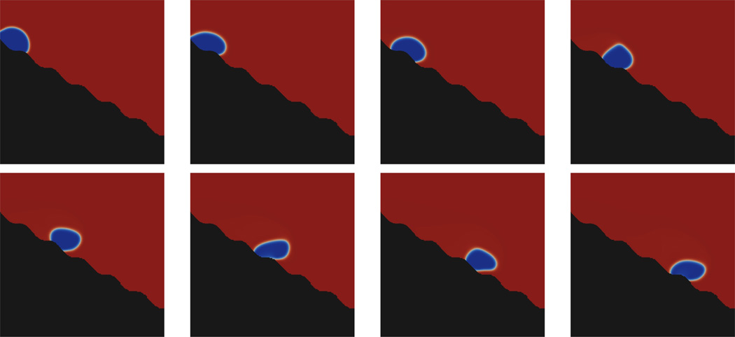
We next consider a droplet sliding down a structured surface first in 2D and then in 3D. Such a geometry is appropriate for applications in micro- and nano- fluidics. Here, the droplet slides down a rippled ramp whose profile is given by the 30° rotation of the graph (x,y), with y(x) = (1.4+0.02 sin(25x)). The extended domain is Ω = [0,1.4]2. The viscosity is ν = 0.001, the gravitational force is F = (0,0,−9.81), the surface tension is σ̃ = 0.1, the mobility is γ = 0.01 and the interface thickness εϕ = ε = 0.01.
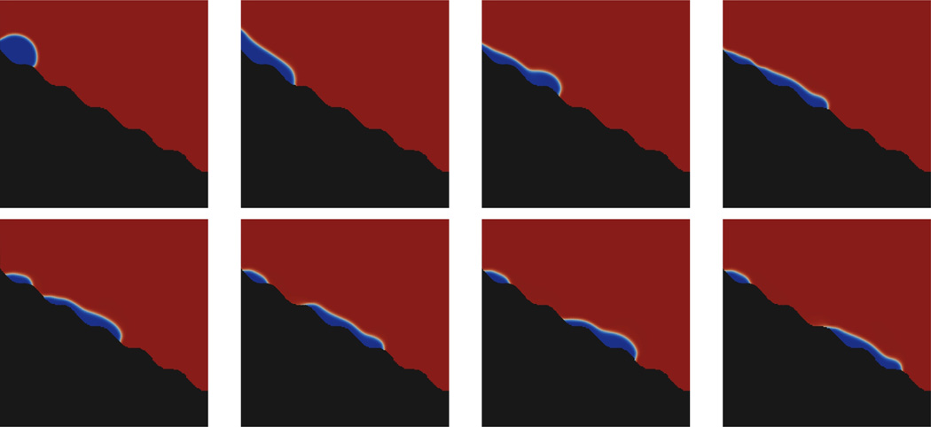
The figures 6–9 show the motion of the droplet with different contact angles between 60° and 150°. The pictures show the contours of the phase-field variable c and thus the position of the droplet between t = 0 and t = 2.0 at equidistant time intervals. The region {ϕ < 0.5} is marked black. Note that there is no significant difference in droplet speed as friction has not been taken into account. In the case of the 60° contact angle the droplet breaks up at early times and a part of it stays in the upper left corner of the ramp while the other part slides down the ramp.
Figure 6.
Droplet with contact angle of 60°sliding down the ramp. Color online.
Figure 9.
Droplet with a contact angle of 150°sliding down the ramp. Color online.
Drop break-up does not occur for the 90°, 120° and 150° contact angle cases; the complete droplet slides down the ramp as seen in Figures 6–9. Interestingly when the contact angle is θ = 150 ° the droplet rotates as it slides down the ramp and even lifts off the ramp occasionally.
The volume of the drop can be calculated by . During the simulation the volume of the drop slightly increased from 0.039938 to 0.039979. Thus, the error in drop volume is 0.1%. Because the numerical discretization for c is conservative, this small error arises from the use of adaptive mesh refinement which is not strictly conservative.
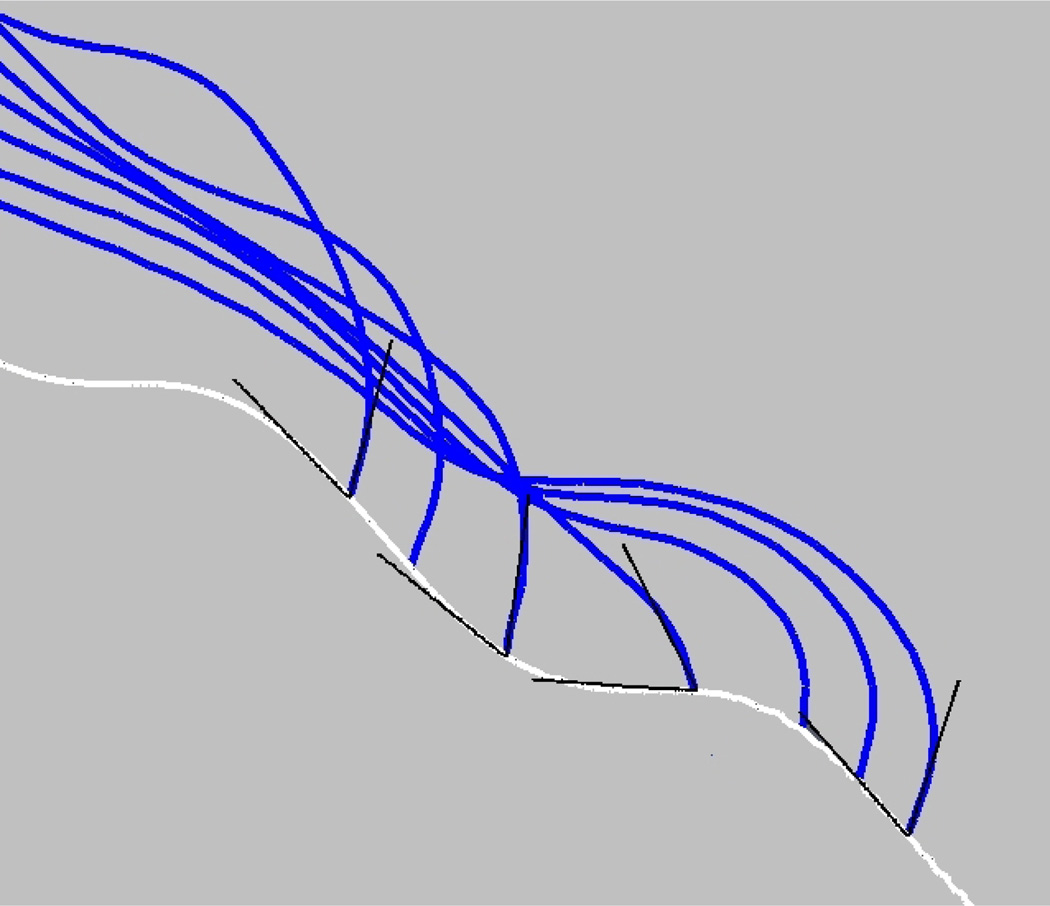
A close up of the droplets reveals that the contact angles for the simulated drops are very nearly that prescribed through the boundary condition. In Figure 10 a droplet with a 60° contact angle boundary condition is shown together with the local coordinate system at the leading tip (showing a 60° angle) as the droplet slides down the ramp. Clearly the error in contact angle is quite small with the largest deviations occuring where the slope of the ramp is the largest and thus the droplet is sliding the fastest (middle of image).
Figure 10.
Overlay of the leading edge of a droplet (blue), with a 60° contact angle boundary condition, shown together with a local 60° coordinate system (black), at different times as the droplet slides down the ramp (white). Color online.
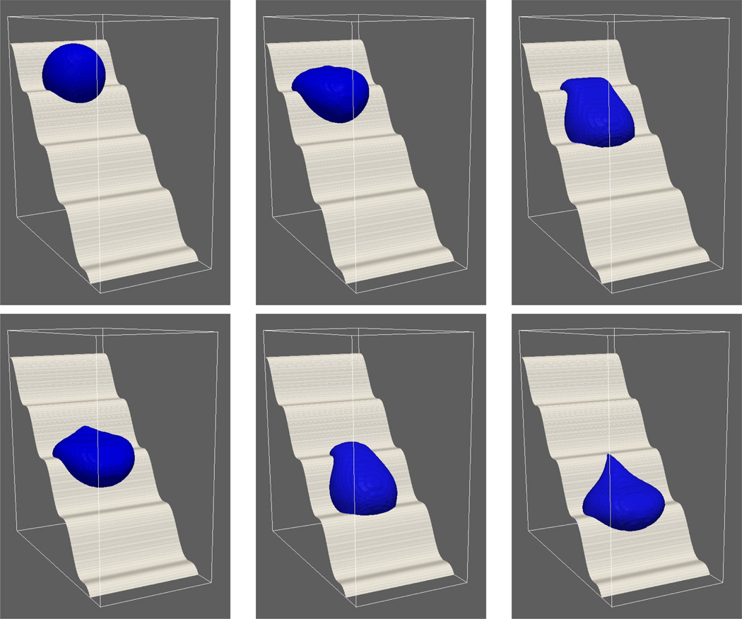
We now consider the same problem in 3D. Figure 11 shows a droplet sliding down a structured 45° ramp with a 90° contact angle. The other parameters are as in 2D except that the mobility is γ = 1.0. In addition, we used a larger interface thickness εϕ = 0.04 for ϕ than for c (ε = 0.01) in order to reduce the number of mesh elements. The droplet remains intact and thickens at the leading edge as it slides down the ramp. Interestingly, the trailing edge of the droplet acquires a rather sharp wedge-like shape.
Figure 11.
Sliding droplet with a 90° contact angle in 3D at times t = 0,0.3,0.62,0.95,1.21,1.42.
4.4 Moving domains
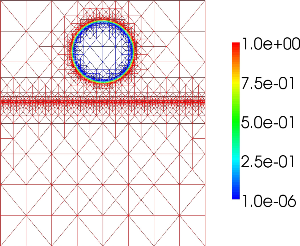
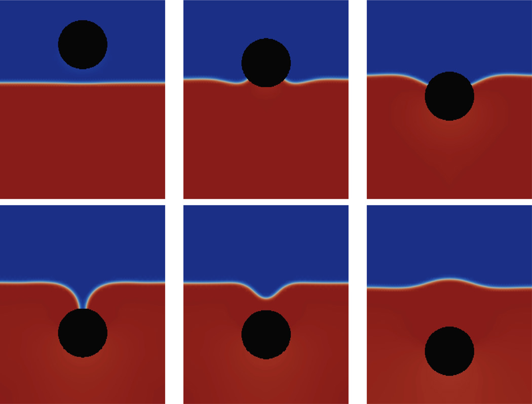
In the next example, we simulate a solid ball impacting a liquid/liquid interface in 2D. An axisymmetric version of this problem was previously simulated by Do-Quang and Amberg (2009) who investigated the effect of different wetting angles on the evolution using a NSCH model with adaptive, boundary-fitted finite elements. Here, we use the diffuse domain formulation with extended domain Ω = [0,1] × [0,1.2]. Figure 12 shows the initial condition for ϕ on the adaptively refined grid; ϕ is set at zero inside a circle of radius 0.15 which describes the solid ball. The function ϕ smoothly tends to one across the boundary of the ball.
Figure 12.
The diffuse domain ϕ at the initial time. Color online.
The diffuse domain moves with a constant velocity g = (0,−1). The viscosity is ν = 0.01, the gravitational force is F = (0,−9.81), the surface tension is σ̃ = 0.1, the mobility is γ = 10 and the interface thickness is εϕ = ε = 0.01. A 90° contact angle boundary condition is imposed. Figure 13 shows the results of the simulations. As the ball impacts the interface, a moving contact line forms on each side of the ball that leads to a narrow thread of upper fluid being pulled down into the lower fluid. Eventually the two contact lines merge, the ball separates from the interface and the fluids rebound upward as the ball falls through the lower fluid.
Figure 13.
The impact of a solid ball into a liquid-liquid interface in 2D. The ball modeled, by the diffuse domain ϕ < 0.5, is colored black. The snapshots are taken at times t = 0, 0.1, 0.3, 0.49, 0.51, 0.61. Color online.
4.5 Serpentine channel
As a final example, we use the DDNSCH model to simulate mixing inside a 2D droplet by chaotic advection which is induced by having the droplet flow through a winding, serpentine channel with thickness comparable to that of the droplet. Muradoglu and Stone (2005) simulated this process by using a finite-volume/front tracking method and discretizing the equations in the complex geometry using a curvilinear grid, and visualizing the mixing using a particle tracking method. Here, we consider a similar configuration using the DDNSCH model, although we use a continuous field to assess the mixing.
The channel geometry is given by two sine functions with period length 0.2π and amplitude 0.2. The vertical distance between the upper and lower channel boundaries is 0.25 and the channel domain is embedded in the extended domain Ω = [−0.2,2.2] × [0,0.8]. Initially, a droplet of diameter 0.16 is placed at the upper left corner of the channel. See Figures 14 and 15.
Figure 14.
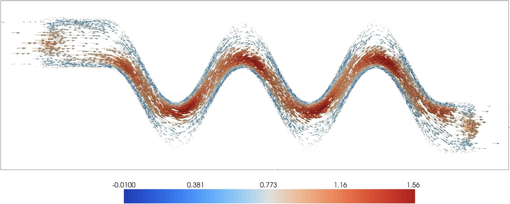
Flow field in a winding, serpentine channel shown on the extended domain Ω. See text for details. Color online.
Figure 15.
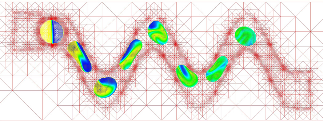
Snapshots of the droplet evolution and interior mixing patterns over time. See text for details. Color online.
Furthermore an additional variable e is used to indicate the concentration of a tracer material within the droplet. Consequently, e satisfies a convection-diffusion equation within the moving and deforming droplet:
where the diffusion parameter D which is chosen to be very small, e.g. 10−8, so that molecular diffusion is small and mixing is primarily due to chaotic advection. Following Li, Lowengrub, Rätz, and Voigt (2009), this equation is reformulated using the diffuse domain approach as
where
approximates the characteristic function of the droplet interior.
In figures, 14–16 the viscosity of the fluids is ν = 0.01, the surface tension is σ̃ = 1.0, the mobility γ = 0.1 and the interface thickness is εϕ = ϕ = 0.01. Further, we added a non-wetting condition by incorporating a penalty formulation in the free energy functional (last term):
Figure 16.
A close-up of the droplet morphologies and the interior mixing patterns at the different times shown in figure 15. Color online.
The corresponding functional derivative results in an additional term in the Cahn-Hilliard equation, which can be incorporated into (15) by setting (Li, Lowengrub, Rätz, and Voigt, 2009)
Finally, we equip the model with a no-slip Dirichlet boundary condition u = 0 on the upper and lower boundaries of the channel. At the inflow (left) and outflow (right) boundary we use a parabolic velocity profile with maximum speed u=(1,0). The resulting flow field through the channel in the absence of the droplet is shown in figure 14.
Figures 15 and 16 show snapshots of the evolving droplets and mixing patterns at times t = 0.02, 0.22, 0.42, 0.62, 0.82, 1.02, 1.22, 1.42. The droplet starts at the upper left corner and consists initially of tracer material in one half of the droplet (yellow) while the remaining tracer free portion is colored blue. The adaptive grid shown figure 15 makes it possible to identify the position of the channel as seen by the refinement along its boundary. Note that the grid is taken from time t = 0.02.
As the droplet flows through the channel, it deforms to an elongated shape it moves downwards and upwards through the straight regions. At the peaks and valleys where the flow changes from downward to upward (and vice versa) and the channel is wider, the surface tension brings the drop back to a more circular shape. Throughout this process, the velocity fields result in significant mixing within the droplet as indicated by the increasingly uniform distribution of green coloring.
5 Conclusions and future work
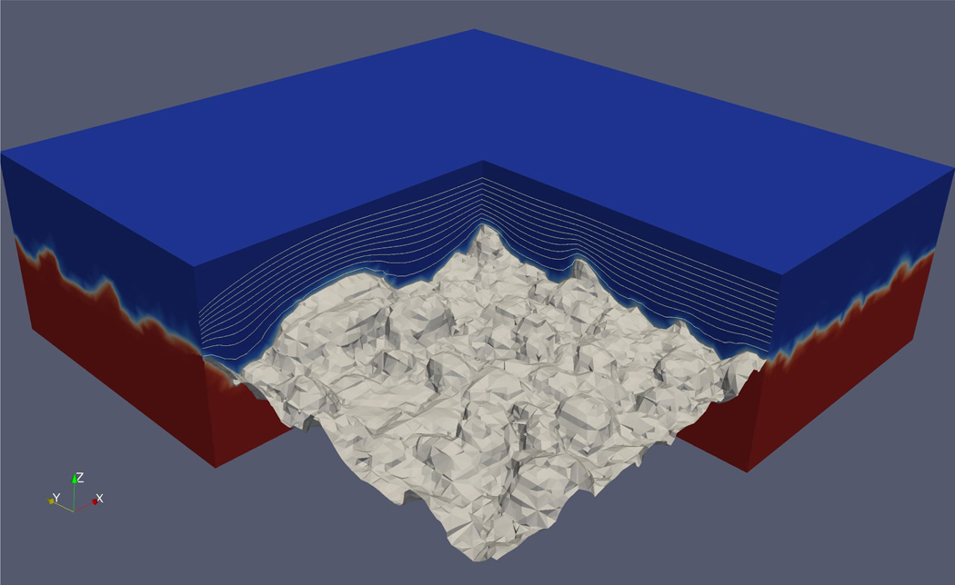
We have extended previous work and presented a diffuse domain approach to simulate two-phase flows in complex geometries. A concentration field was introduced to describe the distribution of one of the fluid phases. The concentration field is coupled to the Navier-Stokes equations for the fluid motion through extra stresses that mimic surface tension and is evolved by an advective Cahn-Hilliard equation that is equipped with boundary conditions that encode contact line information (e.g. equilibrium contact angle). The diffuse interface formulation circumvents mesh generation of complex geometries by embedding the complex domain in a larger, regular domain and reformulating the equations using a a phase-field function that approximates the characteristic function of the complex domain. This is particularly useful in 3D where the development of a high-quality meshes in a complex geometry is a nontrivial problem. The resulting diffuse domain equations on the regular domain were solved by a finite element method although any standard discretization method could be applied. Adaptive mesh refinement was needed to efficiently resolve the transition layers associated with the concentration and phase field variables. We demonstrated the applicability of the diffuse domain approach by solving several typical two-phase flow problems from micro- and nano- fluidics in both stationary and moving domains. While the domains we considered were idealized, any other profiles could be used including those obtained from experimental images and micrographs. For example, in Figure 17, the flow over a realistic thin film taken from an AFM image (Koza, Uhlemann, Gebert, and Schultz, 2008) is shown. The Navier-Stokes equations are solved in the blue region above the thin film with a velocity u = (0.01m/s,0,0) imposed at the upper boundary, no-slip conditions u = 0 imposed on the film surface and periodic conditions are used in the x and y directions. The computational domain is [0,2 × 10−6] × [0,2 × 10−6] × [0,8 × 10−7]m3. The thickness of the fluid layer is approximately 4 × 10⁻⁷ and εϕ = 2 × 10⁻⁸. The density and viscosity of the liquid correspond to that of water; the effect of gravity is not considered. The results reveal that flow near the valleys of the film is suppressed and the fluid is nearly stagnant. This is a first step towards microscopically simulating the effect of flow on electrodeposition and the possibility of controlling the deposition process using magnetic fields, e.g. see Koza, Uhlemann, Gebert, and Schultz (2008).
Figure 17.
AFM image of a thin film grown by electrodeposition, with simulated flow field in a boundary layer of electrolyte. AFM data from Koza, Uhlemann, Gebert, and Schultz (2008). Color online.
An interesting open question is the sharp interface limit of the diffuse domain formulation. For problems without three-phase contact lines, the diffuse domain models converge to classical sharp interface models as the sharp interface thickness tends to zero. However, when a three-phase contact line is present, the classical sharp interface model is singular and the diffuse interface model is thus a singular perturbation. The transition layers for c and ϕ may strongly interact yielding nonuniform convergence in interface thickness. Nevertheless, when the boundary layer thickness εϕ tends to zero, we found convergence of the diffuse domain solution to the solution of the equations and boundary conditions in the original domain, for fixed interface thickness ε. However, if the concentration and phase field functions have the same transition layer thickness ε = εϕ, then further characterization is needed to identify the sharp interface limit ε → 0.
In the models presented here, the interaction between the fluid and the solid boundary was limited to no-slip and contact angle boundary conditions. Further, the motion of the solid was specified. In numerous applications, however, the motion of the solid and fluid are intimately coupled through hydrodynamic forces (e.g., solid particles moving in a flow). In addition, the solid may deform. In these cases, additional equations need to be solved to determine the evolution of the coupled system. For example, when the solid is rigid, the Newton-Euler equations need to be solved for the linear and angular particle velocities. When the solid is deformable, the elasticity equations need to be solved in the solid structure together with continuity of velocity and normal stress boundary conditions at the solid/liquid interface. Thus, a natural extension of this work is the development of a diffuse domain formulation for such fluid structure interactions. This is currently under development.
Figure 7.
Droplet with contact angle of 90°sliding down the ramp. Color online.
Figure 8.
Droplet with a contact angle of 120°sliding down the ramp. Color online.
Acknowledgement
SA and AV acknowledge financial support from DFG Vo-899/6-2 and SFB 609. JL gratefully acknowledges partial support from the National Science Foundation Division of Mathematics and the National Institutes of Health through grant P50GM76516 for a Center of Excellence in Systems Biology at the University of California, Irvine.
References
- Al-Rawahi N, Tryggvason G. Numerical simulation of dendritic solidification with convection: Two-dimensional flow. J. Comput. Phys. 2002;vol. 180:471–496. [Google Scholar]
- Al-Rawahi N, Tryggvason G. Numerical simulation of dendritic solidification with convection: Three-dimensional flow. J. Comput. Phys. 2004;vol. 194:677–696. [Google Scholar]
- Anderson D, McFadden G, Wheeler A. Diffuse interface methods in fluid mechanics. Ann. Rev. Fluid Mech. 1998;vol. 30:139–165. [Google Scholar]
- Balaras E. Modeling complex boundaries using an external force on fixed cartesian grids in large-eddy simulations. Comput. Fluids. 2004;vol. 33:375–404. [Google Scholar]
- Bertozzi A. The mathematics of moving contact lines in thin liquid films. AMS Notices. 1998;vol. 45:689–697. [Google Scholar]
- Biros G, Ying L, Zorin D. A fast solver for the Stokes equations with distributed forces in complex geometries. J. Comput. Phys. 2003;vol. 193:317–348. [Google Scholar]
- Borazjani I, Ge L, Sotiropoulos F. Curvilinear immersed boundary method for simulating fluid structure interaction with complex 3d rigid bodies. J. Comput. Phys. 2008;vol. 227:7587–7620. doi: 10.1016/j.jcp.2008.04.028. [DOI] [PMC free article] [PubMed] [Google Scholar]
- Boyer F. A theoretical and numerical model for the study of incompressible mixture flows. Computers and Fluids. 2002;vol. 31(no. 1):41–68. [Google Scholar]
- Bueno-Orovio A, Perez-Garcia V. Spectral smoothed boundary methods: The role of external boundary conditions. Numer. Meth. Partial Diff. Eqns. 2006;vol. 22:435–448. [Google Scholar]
- Bueno-Orovio A, Perez-Garcia V, Fenton F. Spectral methods for partial differential equations in irregular domains: The spectral smoothed boundary method. SIAM J. Sci. Comput. 2006;vol. 28:886–900. [Google Scholar]
- Choi J-I, Oberoi R, Edwards J, Rosati J. An immersed boundary method for complex incompressible flows. J. Comput. Phys. 2007;vol. 224:757–784. [Google Scholar]
- Chorin AJ. Numerical solution of the Navier-Stokes equations. Math. Comp. 1968;vol. 22 [Google Scholar]
- Chung M-H. Cartesian cut cell approach for simulating incompressible flows with rigid bodies of arbitrary shape. Computers & Fluids. 2006;vol. 35:607–623. [Google Scholar]
- Davis S. Interfacial fluid dynamics. In: Batchelor G, Moffatt H, Worster M, editors. Perspectives in Fluid Dynamics. Cambridge University Press; 2002. [Google Scholar]
- Davis TA. Algorithm 832: Umfpack v4.3—an unsymmetric-pattern multifrontal method. ACM Trans. Math. Softw. 2004;vol. 30(no. 2):196–199. [Google Scholar]
- de Gennes P. Wetting: statics and dynamics. Rev. Mod. Phys. 1985;vol. 57:827–863. [Google Scholar]
- de Zelicourt D, Ge L, Wang C, Sotiropoulos F, Gilmanov A, Yoganathan A. Flow simulations in arbitrarily complex cardiovascular anatomies– an unstructured Cartesian grid approach. Computers & Fluids. 2009;vol. 38:1749–1762. [Google Scholar]
- Deng J, Shao X-M, Ren A-L. A new modification of the immersed-boundary method for simulating flows with complex moving boundaries. Int. J. Num. Meth. Fluids. 2006;vol. 52:1195–1213. [Google Scholar]
- Do-Quang M, Amberg G. The splash of a solid sphere impacting on a liquid surface: Numerical simulation of the influence of wetting. Physics of Fluids. 2009;vol. 21(no. 2) [Google Scholar]
- Duarte C, Babuska I, Oden J. Generalized finite element methods for three-dimensional structural mechanics problems. Comp. Struct. 2000;vol. 77:215–232. [Google Scholar]
- Emmerich H. Advances of and by phase-field modeling in condensed-matter physics. Adv. Phys. 2008;vol. 57:1–87. [Google Scholar]
- Feng X. Fully discrete finite element approximations of the Navier–Stokes–Cahn-Hilliard diffuse interface model for two-phase fluid flows. SIAM J. Numer. Anal. 2006;vol. 44(no. 3):1049–1072. [Google Scholar]
- Fenton F, Cherry E, Karma A, Rappel W-J. Modeling wave propagation in realistic heart geometries using the phase-field method. Chaos. 2005;vol. 15:013502. doi: 10.1063/1.1840311. [DOI] [PubMed] [Google Scholar]
- Gao F, Ingram D, Causon D, Mingham C. The development of a Cartesian cut cell method for incompressible viscous flows. Int. J. Num. Meth. Fluids. 2007;vol. 54:1033–1053. [Google Scholar]
- Gilmanov A, Acharya S. A hybrid immersed boundary and material point method for simulating 3d fluid-structure interaction problems. Int. J. Num. Meth. Fluids. 2008;vol. 56:2151–2177. [Google Scholar]
- Gilmanov A, Sotiropoulos F. A hybrid Cartesian/immersed boundary method for simulating flows with 3d, geometrically complex, moving bodies. J. Comput. Phys. 2005;vol. 207:457–492. [Google Scholar]
- Glowinksi R, Pan T, Periaux J. Numerical simulation of a multistore separation phenomenon: A fictitious domain approach. Comp. Meth. Appl. Mech. Eng. 2006;vol. 195:5566–5581. [Google Scholar]
- Glowinsky R, Pan T, Hesla T, Joseph D, Periaux J. A fictitious domain approach to the direct numerical simluation of incompessible viscous flow past moving rigid bodies: Application to particulate flow. J. Comput. Phys. 2001;vol. 169:363–426. [Google Scholar]
- Gong Y, Li B, Li Z. Immersed-interface finite-element method for elliptic interface problems with non-homogeneous jump conditions. SIAM J. Numer. Anal. 2008;vol. 26:472–495. [Google Scholar]
- Gránásy L, Pusztai T, Saylor D, Warren JA. Phase field theory of heterogeneous crystal nucleation. Physical Review Letters. 2007;vol. 98(no. 3):035703. doi: 10.1103/PhysRevLett.98.035703. [DOI] [PubMed] [Google Scholar]
- Hohenberg P, Halperin B. Theory of dynamic critical phenomena. Rev. Mod. Phys. 1977;vol. 49:435–479. [Google Scholar]
- Hu H, Patankar N, Zhu M. Direct numerical simulations of fluid-solid systems using the arbitrary Lagrangian-Eulerian technique. J. Comput. Phys. 2001;vol. 169:427–462. [Google Scholar]
- Jacqmin D. Calculation of two-phase navier-stokes flows using phase-field modeling. Journal of Computational Physics. 1999:96–127. [Google Scholar]
- Kalliadasis S, Chang H-C. Apparent dynamic contact angle of an advancing gas-liquid meniscus. Phys. Fluids. 1994;vol. 6:12–23. [Google Scholar]
- Kay D, Welford R. Efficient numerical solution of Cahn-Hilliard-Navier-Stokes fluids in 2d. SIAM J. Sci. Comput. 2007;vol. 29(no. 6):2241–2257. [Google Scholar]
- Kirkpatrick M, Armfield S, Kent J. A representation of curved boundaries for the solution of the Navier-Stokes equations on a staggered three-dimensional Cartesian grid. J. Comput. Phys. 2003;vol. 184:1–36. [Google Scholar]
- Kockelkoren J, Levine H, Rappel W-J. Computational approach for modeling intra- and extracellular dynamics. Phys. Rev. E. 2003;vol. 68:037702. doi: 10.1103/PhysRevE.68.037702. [DOI] [PubMed] [Google Scholar]
- Koza J, Uhlemann M, Gebert A, Schultz L. The effect of magnetic fields on electrodeposition of CoFe alloys. Electrochim. Acta. 2008;vol. 53:5344–5353. [Google Scholar]
- Kropinski M. Integral equation methods for particle simulations in creeping flows. Comp. Math. Appl. 1999;vol. 38:67–87. [Google Scholar]
- Levine H, Rappel W-J. Membrane-bound Turing patterns. Phys. rev. E. 2005;vol. 72:061912. doi: 10.1103/PhysRevE.72.061912. [DOI] [PubMed] [Google Scholar]
- Li X, Lowengrub J, Rätz A, Voigt A. Solving pdes in complex geometries: A diffuse domain approach. Commun. Math. Sci. 2009;vol. 7:81–107. doi: 10.4310/cms.2009.v7.n1.a4. [DOI] [PMC free article] [PubMed] [Google Scholar]
- Li Z, Lin T, Wu X. New Cartesian grid methods for interface problems using the finite element formulation. Num. Math. 2003;vol. 96:61–98. [Google Scholar]
- Lin P. A fixed-grid model for simulation of a moving body in free surface flows. Computers & Fluids. 2007;vol. 36:549–561. [Google Scholar]
- Lowengrub J, Truskinovsky L. Quasi-incompressible Cahn-Hilliard fluids and topological changes. Proc. Roy. Soc. London A. 1998;vol. 454:2617–2654. [Google Scholar]
- Mayo A. The fast solution of Poisson’s and the biharmonic equations on irregular regions. SIAM J. Numer. Anal. 1984;vol. 21:285–299. [Google Scholar]
- Melenk J, Babuska I. The partition of unity finite element method: Basic theory and applications. Comp. Meth. Appl. Mech. Eng. 1996;vol. 139:289–314. [Google Scholar]
- Mittal R, Dong H, Bozkurttas M, Najjar F, Vargas A, von Loebbecke A. A versatile sharp interface immersed boundary method for incompressible flows with complex boundaries. J. Comput. Phys. 2007;vol. 227:4825–4852. doi: 10.1016/j.jcp.2008.01.028. [DOI] [PMC free article] [PubMed] [Google Scholar]
- Muradoglu M, Kayaalp A. An auxilliary grid method for computations of multiphase flows in complex geometries. J. Comput. Phys. 2006;vol. 214:858–877. [Google Scholar]
- Muradoglu M, Stone HA. Mixing in a drop moving through a serpentine channel: A computational study. Physics of Fluids. 2005;vol. 17(no. 7) [Google Scholar]
- Oden J, Duarte C, Zienkiewicz O. A new cloud-based hp finite element method. Comp. Meth. Appl. Mech. Eng. 1998;vol. 153:117–126. [Google Scholar]
- Oron A, Davis S, Bankoff S. Long-scale evolution of thin liquid films. Rev. Mod. Phys. 1997;vol. 69:931–980. [Google Scholar]
- Pao J, Pan T, Glowinski R, Joseph D. A fictitious domain/distributed Lagrange multiplier method for the particulate flow for Oldroyd-B fluids: A positive definiteness preserving approach. J. Non-Newtonian Fluid Mech. 2009;vol. 156:95–111. [Google Scholar]
- Rätz A, Voigt A. PDE’s on surfaces - a diffuse interface approach. Comm. Math. Sci. 2006;vol. 4:575–590. [Google Scholar]
- Shinn A, Goodwin M, Vanka S. Immersed boundary computations of shear- and buoyancy-driven flows in complex enclosures. Int. J. Heat Mass Transfer. 2009;vol. 52:4082–4089. [Google Scholar]
- Singer-Loginova I, Singer H. The phase field technique for modeling multiphase materials. Rep. Prog. Phys. 2008;vol. 71:106501. [Google Scholar]
- Teigen K, Li X, Lowengrub J, Wang F, Voigt A. A diffuse-interface approach for modeling transport, diffusion and adsorption/desorption of material quantities on a deformable interface. Comm. Math. Sci. 2010 doi: 10.4310/cms.2009.v7.n4.a10. in press. [DOI] [PMC free article] [PubMed] [Google Scholar]
- Teigen K, Song P, Lowengrub J, Voigt A. A diffuse interface method for two-phase flows with soluble surfactants. J. Comput. Phys. 2010 doi: 10.1016/j.jcp.2010.09.020. in review. [DOI] [PMC free article] [PubMed] [Google Scholar]
- Tryggvason G, Buner B, Esmaeeli A, Juric D, Al-Rawahi N, Tauber W, Han J, Nas S, Jan Y-J. A front-tracking method for the computation of multiphase flow. J. Comput. Phys. 2001;vol. 169:708–759. [Google Scholar]
- Tseng Y-H, Ferziger J. A ghost-cell immersed boundary method for flow in complex geometry. J. Comput. Phys. 2003;vol. 192:593–623. [Google Scholar]
- Udaykumar H, Kan H-C, Shyy W, Tran-Son-Tay R. Multiphase dynamics in arbitrary geometries on fixed Cartesian grids. J. Comput. Phys. 1997;vol. 137:366–405. [Google Scholar]
- Udaykumar H, Mittal R, Rampunggoon P, Khanna A. A sharp interface Cartesian grid method for simulating flows with complex moving boundaries. J. Comput. Phys. 2001;vol. 174:345–380. [Google Scholar]
- Uzgoren E, Sim J, Shyy W. Marker-based, 3-d adaptive Cartesian grid method for multiphase flows around irregular geometries. Commun. Comput. Phys. 2009;vol. 5:1–41. [Google Scholar]
- Verfürth R. A review of a posteriori error estimation and adaptive meshrefinement techniques. Chichester: John Wiley & Sons; 1996. Wiley-Teubner Series Advances in Numerical Mathematics; p. 127. Stuttgart: B. G. Teubner. vi. [Google Scholar]
- Vey S, Voigt A. Amdis: adaptive multidimensional simulations. Computing and Visualization in Science. 2007;vol. 10(no. 1):57–67. [Google Scholar]
- Villanueva W, Amberg G. Some generic capillary-driven flows. Int. J. Multiphase Flow. 2006;vol. 32(no. 9):1072–1086. [Google Scholar]
- Wang MY, Zhou S. Phase field: A variational method for structural topology optimization. CMES. 2004;vol. 6:547–566. [Google Scholar]
- Xie H, Koshizuka S, Oka Y. Modeling the wetting effects in droplet impingement using particle method. CMES. 2007;vol. 18:1–16. [Google Scholar]
- Xu S, Wang Z. An immersed interface method for simulating the interaction of a fluid with moving boundaries. J. Comput. Phys. 2006;vol. 216:454–493. [Google Scholar]
- Yu HC, Chen HY, Thornton K. Smoothed boundary method for solving partial differential equations with general boundary conditions on complex boundaries. 2009 submitted. [Google Scholar]
- Yu Z, Shao X. A direct-forcing fictitious domain method for particulate forces. J. Comput. Phys. 2007;vol. 227:292–314. [Google Scholar]
- Yu Z, Thien-Phan N, Fan Y, Tanner R. Viscoelastic mobility problem of a system of particles. J. Non-Newtonian Fluid Mech. 2002;vol. 104:87–124. [Google Scholar]
- Zhao H-K, Merriman B, Osher S, Wang L. Capturing the behavior of bubbles and drops using the variational level set approach. J. Comput. Phys. 1998;vol. 143:495–418. [Google Scholar]
- Zhou C, Yue P, Feng J, Ollivier-Gooch C, Hu H. 3D phase-field simulations of interfacial dynamics in Newtonian and viscoelastic fluids. J. Comput. Phys. 2010;vol. 229:498–511. [Google Scholar]


