Abstract
When a tensile strain is applied to a film supported on a compliant substrate, a pattern of parallel cracks can channel through both the film and substrate. A linear-elastic fracture-mechanics model for the phenomenon is presented to extend earlier analyses in which cracking was limited to the film. It is shown how failure of the substrate reduces the critical strain required to initiate fracture of the film. This effect is more pronounced for relatively tough films. However, there is a critical ratio of the film to substrate toughness above which stable cracks do not form in response to an applied load. Instead, catastrophic failure of the substrate occurs simultaneously with the propagation of a single channel crack. This critical toughness ratio increases with the modulus mismatch between the film and substrate, so that periodic crack patterns are more likely to be observed with relatively stiff films. With relatively low values of modulus mismatch, even a film that is more brittle than the substrate can cause catastrophic failure of the substrate. Below the critical toughness ratio, there is a regime in which stable crack arrays can be formed in the film and substrate. The depth of these arrays increases, while the spacing decreases, as the strain is increased. Eventually, the crack array can become deep enough to cause substrate failure.
1 Introduction
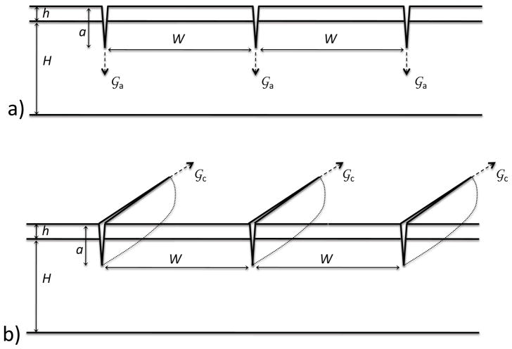
A coating, thin film, or surface layer supported on a substrate can fracture into a pattern of parallel cracks when subjected to a tensile stress [1, 2, 3, 4, 5]. The cracks are limited to the surface layer if it is more compliant than the substrate. However, the cracks will penetrate the interface and propagate within the substrate if a stiff film is supported on a compliant substrate [4, 6]. While there have been several studies on the cracking of stiff coatings on polymers [7, 8, 9, 10, 11], the associated analyses have generally assumed that only the coating fractures. Recent experimental observations [12] on a system consisting of a thin metal film on an elastomeric substrate demonstrated stable fracture patterns with cracks clearly propagating within the substrate. This observation was the original motivation for the present analysis to investigate how fracture of the substrate affects the formation of crack arrays (Fig. 1). The results of the analysis show how the crack spacing and depth depend on the ratio between the film and substrate modulus and on the ratio between the film and substrate toughness. In particular, the results help delineate the regimes in which substrate fracture may have a significant effect on the failure of coated systems from those that do not. Finally, the results establish criteria for when stable fracture patterns do not form, but the propagation of a single crack in the film induces catastrophic failure of the substrate.
Figure 1.
The geometry considered in this paper. A stiff film of thickness h and elastic constants Ef and νf is supported on a compliant substrate of thickness H and elastic constants Es and νs. There is a uniform crack array of deptha and spacing W. a) The two-dimesnional geometry, appropriate for cracks propagating perpendicular to the interface and into the substrate. b) The configuration for crack channeling (propagation parallel to the interface).
The fracture behavior of stiff films on compliant polymeric substrates has relevance for a number of applications. The level of modulus mismatch between the two components for some of these applications can be as extreme as 104 to 1 when a metal film is supported by an elastomer. For example, elastomeric actuators deform in response to a high electric field between thin metal electrodes on the surfaces of elastomeric dielectrics [13, 9, 14]. Oxide and metal coatings on a range of different polymers, including elastomers, form the basis of flexible electronics such as organic light-emitting diodes [15] or solar cells [16, 17]. Failure of the surface layer is one of the limitations on the flexibility of such devices [18, 19, 20, 21]. More generally, metal-polymer multilayers are commonly used for electronic packaging [22]. Metal films have been used as permeability barriers for polymers in the food packaging industry for many years, and there have been recent studies on the use of oxide [23] and diamond-like carbon films for this purpose [24]. Integrity of the permeability barrier is compromised by cracking. A practical application in which cracking of stiff layers on elastomers is desirable is in the fabrication of tunable biological devices and nano-channels [25, 26, 27]. Finally, it is well known that a stiff surface layer on a polymer, such as might result from the application of a paint film or from environmental degradation, has a tendency to make the underlying polymer substrate fail in a brittle mode [28, 29, 30]. The results of this paper may provide some insight into this particular failure mode.
By way of background, the mechanics of crack formation will be summarized for systems in which the cracks are confined to a surface layer. Below a critical level of strain, εc, no cracks can propagate. This critical strain depends on the thickness of the film, h, the thickness of the substrate, H, the elastic constants of the film and substrate, and the toughness of the film, Γf:
| (1) |
The Dundurs parameters, α and β, are the non-dimensional parameters which define the modulus mismatch in plane geometries; they are given by [31]
| (2) |
and
| (3) |
where Ē = E/(1 − ν2) and f (ν) = (1 −2ν)/[2(1 − ν)] in plane strain, E is Young’s modulus, ν is Poisson’s ratio, and the subscripts f and s denote the film and substrate respectively. In particular, the results of Beuth [4] give the critical tensile strain, εc, for a single crack to channel across the film penetrating all the way to the interface. For an infinitely thick substrate this is given by
| (4) |
where g(α, β) is given in Ref. [4] for values of α up to 0.99; the effects of the substrate thickness are incorporated in Refs. [32] and [33].
When the strain exceeds the critical value given by Eqn. 4, a periodic array of cracks can channel across the system. These cracks relieve the strain energy locally within the film, but the overall load-bearing capability of the system is maintained by load transfer through the substrate under the broken film. While the spacing between the cracks can be limited by the density of intrinsic flaws responsible for initiating cracks, energy considerations suggest that, if the intrinsic flaw density is suffciently high, there is a characteristic or average crack spacing, S, that varies with the applied strain, εo, and is of the non-dimensional form1
| (5) |
A number of studies have shown that this crack spacing decreases as the strain increases [1, 2, 3, 5]. The development of detailed mathematical models for the spacing is complicated by the approximations that need to be made to describe the sequence in which the crack pattern evolves. The precise evolution of a crack pattern will depend on the history of the pattern developed at lower strains; this will necessarily be stochastic in nature. While recognizing the limitation that this issue imposes, two modelling approaches have been developed to analyze the crack spacing. In one approach, the minimum spacing between two cracks that just prevents a third crack from propagating between them is taken to be the characteristic spacing [3]. In the other approach, the characteristic spacing is assumed to be that which minimizes the total energy of the cracked body [2, 5]. As an example, when the cracks are confined to a thin surface layer of a system with no modulus mismatch, this latter approach results in a characteristic crack spacing of [2]
| (6) |
so that, consistent with experimental observations [2], the spacing is inversely dependent on the applied strain. It is this energy-minimization approach that is used as the basis for the calculations of the present paper.
The depth to which cracks penetrate the substrate depends on the level of the applied strain and on the toughness of the substrate. The extent to which this, in turn, affects the spacing is not currently known, but will become evident from the results of this study. In non-dimensional terms, the spacing has a form that is very similar to Eqn. 5, but includes an additional term involving the substrate toughness:
| (7) |
Changes in the energy associated with the propagation of a crack, and hence the characteristic spacing, can be calculated relatively easily if the crack depth is defined by the film thickness. However, the present problem is complicated by the fact that the crack depth is not known a priori, and needs to be determined simultaneously with the crack spacing. This is the problem that provides the focus of the present paper.
2 Equilibrium configuration of substrate cracks
The first issue to be addressed is why cracks that penetrate through a film and into the substrate can be stable under a remote applied tension. It has long been recognized that cracks can propagate in a stable fashion below the interface when they are driven by a residual tension in the film [34, 35]. For example, Ye et al. [34] have shown that when a film of thickness h is subjected to a residual tensile strain, the energy-release rate at the tip of a crack penetrating from the film into the substrate decreases with crack depth, giving stable crack growth. The energy-release rate at the tip of a single, crack of depth, a, much greater than the film thickness, h, tends to a limit of [36]
| (8) |
However, the present problem addresses the case of a strain being applied to the substrate, as well as to the film. In this case, the corresponding energy-release rate for a single, deep crack increases with crack depth, and is of the form [36]:
| (9) |
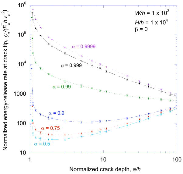
An applied load, as opposed to one arising from a residual stress in the film, is therefore expected to result in unstable crack propagation within the substrate. Stability in this case is provided if there is a large mismatch in modulus between the film and substrate. If the film is very stiff relative to the substrate, the stress in the film is much larger than the stress in the substrate. Therefore, the stresses acting on relatively shallow cracks are dominated by the film stresses, and the energy-release rate falls with increasing crack depth as in Eqn. 8. If the crack is deep enough, the substrate stresses dominate, and the behavior is unstable. These two regimes of stable and unstable behavior are illustrated by the plots of Fig. 2 that show numerical solutions for how the crack depth, a, affects the energy-release rate,
 , at the tips of cracks in a periodic and uniform array (Fig. 1a). The array is stable when the cracks are shallow and the film is stiff, but it has a tendency to become unstable as the cracks get deeper, or as α → 0.
Figure 2.
The energy-release rate tending to drive the cracks of a uniform array into the substrate,
 , plotted as a function of crack depth.
 exhibits both stable and unstable behavior when loaded by a remote tensile strain, if the surface layer has a higher modulus than the substrate.
The calculations used to obtain the results presented in Fig. 2 were performed using the commercial finite-element code ABAQUS. The substrate and surface layer were modeled using linear-elastic, 4-node, bilinear, plane-strain quadrilateral elements. The substrate was modeled using hybrid, constant-pressure, hourglass-control, reduced-integration elements, and the surface layer was modeled using incompatible-mode elements. The calculations were done keeping the elastic properties of the substrate fixed and varying the properties of the surface layer so that the magnitude of β was kept to less than 0.04 as α was varied. The bottom surface of the substrate and the top surface of the film were traction-free. Periodic boundary conditions were used on either side of the crack; these boundaries represented the mid-points between neighboring cracks in a periodic array. One boundary was held fixed, while the other had a nodal displacement imposed on it to represent the applied strain. The J-integral was calculated around the crack tip using a procedure embedded within the finite-element code. A mesh-sensitivity study was conducted to assess the magnitude of the numerical uncertainties which are represented as error bars in the accompanying plots.
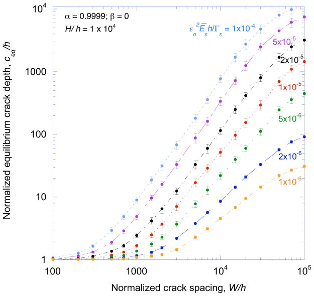
The equilibrium depth, ceq, for a periodic crack array can be deduced from results such as those shown in Fig. 2 by equating the crack-tip energy-release rate to the toughness of the substrate. Figure 3 illustrates how this equilibrium depth can vary with crack spacing for different strains. This figure emphasizes that there are multiple equilibrium configurations, with different depths and spacings, for a given value of strain. As a result, this type of calculation provides no indication as to how an array of cracks in a coated system might develop. However, it should be noted that the experimental observations clearly indicated that the crack arrays form by channeling across the system as indicated in Fig. 1b. The appropriate driving force for channeling is therefore the energy-release rate acting parallel to the interface,
 , not the one discussed above which acts in a direction perpendicular to the interface. As will be shown in the subsequent sections, such a channeling analysis does provide insights into how the crack arrays form.
Figure 3.
The equilibrium depth for a uniform crack array depends on the applied strain, film thickness, substrate toughness, and crack spacing.
3 Channeling cracks in the substrate
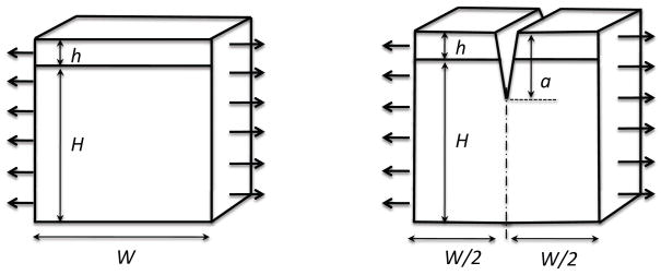
The basic concept behind the channeling analysis is a consideration of the energy changes between material far ahead of the propagating array and material within the cracked wake [37]. The geometry of Fig, 4a shows a slice of material (cut perpendicular to the direction in which the cracks grow) far ahead of a crack array. The elastic energy (per unit thickness) stored in this slice of width W is uo(W). The geometry of Fig. 4b shows the same slice of material, but in the wake of the crack array. The elastic energy (per unit thickness) stored in this cracked slice is uc(a, W). The energy associated with the creation of crack surfaces, Γ, provides an additional contribution to the total energy of the cracked geometry. For a thin-film geometry, the effective toughness resisting channeling is given by Γ = Γs + (h/a)(Γf − Γs). The total loss in energy, (per unit area of interface) between the uncracked and cracked configurations is given by
Figure 4.
The basic geometries of unit thickness used for the calculations in this paper. The substrate is of thickness H and the film is of thickness h. (a) An uncracked slice of material of width W from which uo(W) is calculated. (b) The same element with a crack of depth a in the middle, from which uc(a, W) is calculated. (c) A crack with an internal pressure, corresponding to the stress field in the uncracked configuration, from which uo(W) − uc(a, W) is calculated directly.
| (10) |
Channeling can occur if this loss in energy is greater than zero. Furthermore, it is assumed that for a given geometry and set of material properties, the characteristic depth, c, and spacing, S, are that develop at a given applied strain are the ones that maximize this total energy loss.
The first step in the analysis was a numerical calculation of the difference between uo(W) and uc(a, W), as a function of crack depth for a fixed crack spacing, using the commercial finite-element code ABAQUS. One approach was to compute uc(a, W) numerically and subtract it from uo(W) (for which a simple analytical expression exists). However, this approach is very prone to numerical errors when the cracks are relatively shallow and α is below about 0.9. The other approach (Fig. 4c) was to calculate the energy difference directly by calculating the crack-opening displacements, δ(y), and numerically integrating the expression:
| (11) |
Once this difference in energy was calculated, the total energy change was found from Eqn. 10. The characteristic depth and spacing were then determined by finding the coupled pair of a and W that resulted in the maximum change in total energy for a given strain. Estimates of the numerical uncertainties were made by comparing the results from different calculations and from mesh-sensitivity analyses. The influence of these numerical uncertainties on the subsequent calculations were also studied, and are reflected in the magnitude of the error bars on the accompanying plots.
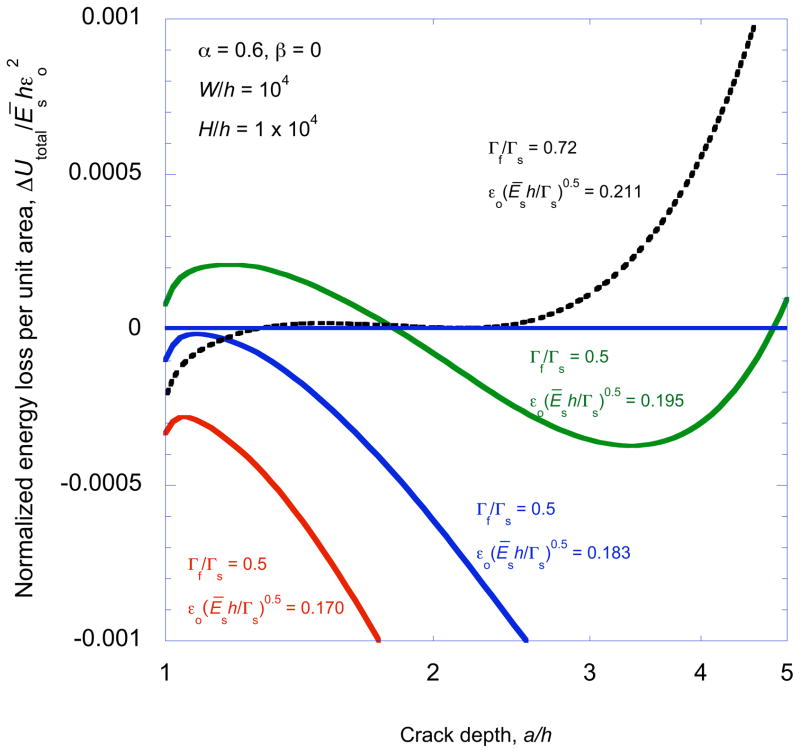
The total energy loss calculated from Eqn. 10 exhibited different forms, corresponding to different types of cracking behavior. These can be best understood by reference to Fig. 5 which shows representative plots for the change in total energy as a function of crack depth. These results are given for one specific modulus mismatch ratio, but different values of strain and toughness ratio for an isolated single crack channeling across the film and substrate. In this figure, positive energy losses correspond to conditions for which it is thermodynamically possible for channeling to occur. Furthermore, remembering that
 = −∂uc(a, W)/∂a, it can be shown that any long crack that has been formed will be drawn deeper into the substrate when ∂ΔUtotal/∂a > 0, but that there is a thermodynamic barrier for crack extension into the substrate when ∂ΔUtotal/∂a < 0. Maxima and minima on this figure correspond to equilibrium conditions where
 = Γs.
= Γs.
Figure 5.
An example of a non-dimensional plot of the total energy loss (per unit area) ΔUtotal/Ēshεo2 against crack depth a/h for an isolated crack and for different values of normalized strain and toughness ratio.
There are a number of points to be noted from Fig. 5. First, as expected for α > 0, any crack at a depth of a/h = 1 will be drawn into the substrate. As discussed in more detail in the subsequent section, substrate fracture reduces the critical strain for the onset of channeling below that given by Eqn. 4. Second, cracks that extend deep enough into the substrate are always unstable; if deep cracks develop they will cause catastrophic failure of the substrate, as discussed in the previous section. Third, there are conditions for which stable cracks exist at equilibrium depths indicated by the local maxima in ΔUtotal. Finally, there are conditions that result in there being no stable depth at which an isolated crack can channel. There is a critical toughness ratio, Γf/Γs at which the stable and unstable equilibrium depths coalesce at exactly the strain required to permit channeling to occur. For toughness ratios greater than this value, channel cracking can not occur; the only mode of crack propagation is catastrophic failure of the substrate.
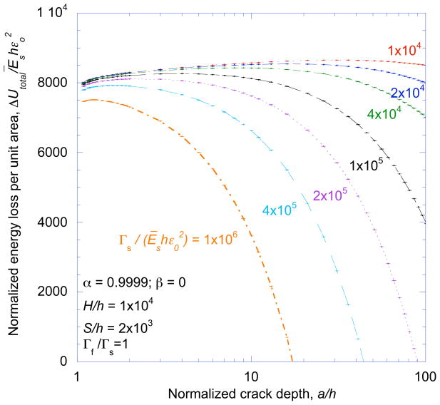
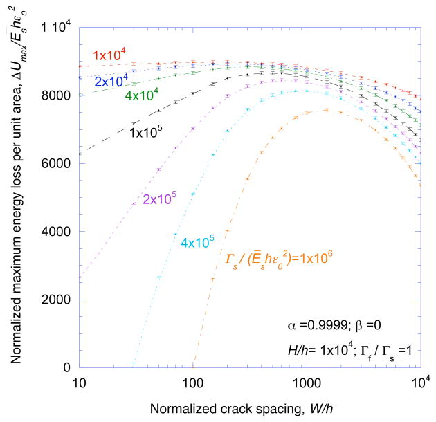
The characteristic spacing, S, and depth, c, of an array are assumed to be the values of W and a that maximize the energy loss of the system. This follows earlier models [2, 5] in assuming that the crack spacing that will evolve can be approximated as the one that will minimize the total energy of the system. The process by which S and c were found is illustrated in Figs. 6 and 7. First, ΔUtotal was plotted as a function of crack depth for a given spacing and normalized strain (Fig. 6). ΔUmax, the maximum energy loss for a particular spacing and strain was identified from this plot. The calculation was then repeated for different crack spacings, and the results used to create a plot of ΔUmax against W/h for a given value of strain (Fig. 7). Finally, the spacing that gave the largest value of ΔUmax at a given strain was obtained from this plot, and equated to the characteristic spacing at that strain. (A corresponding depth was also associated with this condition.) This process was repeated for a series of strains, so that the characteristic spacing and depth could be obtained as a function of strain.
Figure 6.
A non-dimensional plot of the total energy loss (per unit area) ΔUtotal/Ēshεo2 against crack depth a/h for different values of normalized strain.
Figure 7.
A non-dimensional plot of the maximum energy loss (per unit area) ΔUmax/Ēshεo2 as a function of crack spacing for different values of applied strain.
4 Discussion
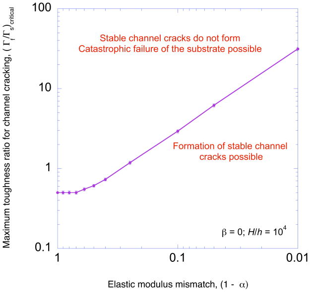
The behavior of a single crack channeling across a film and substrate is discussed first as the results can be directly compared to the existing solutions of Beuth [4] for which the channel crack is confined to the film. These calculations for the single crack were conducted for a crack spacing of W/h = 104, which was large enough to avoid any significant interactions between neighboring cracks for α ≤ 0.99. Figure 8 illustrates how the critical toughness to induce catastrophic substrate failure rather than channel cracking increases with modulus mismatch ratio. At low values of modulus mismatch, substrate failure rather than channeling will occur if the substrate is more than twice as tough as the film. This can be illustrated by a simple analytical result for α = 0. The strain required to propagate a single channel crack across a film in a homogeneous system is [37]
Figure 8.
The critical toughness ratio for the formation of crack arrays plotted as a function of modulus mismatch ratio. Catastrophic failure of the substrate will occur, rather than the propagation of a channel crack, if the toughness of the film relative to the substrate is greater than the critical toughness ratio.
| (12) |
The energy-release rate,
 for a surface crack in a homogeneous system subjected to a tensile strain of εo with its tip at the interface between the film and substrate is [36]
| (13) |
Using the condition that the substrate will fail catastrophically if
 ≥ Γs, it can be shown that the condition for channeling can not be met without also meeting the condition for substrate failure if Γf/Γs ≥ 0.500. It can be seen from Fig. 8 that a film less tough than the substrate can induce catastrophic failure for a modulus mismatch ratio as high as α ≈ 0.71. At higher values of modulus mismatch, the critical toughness increases with alpha according to
| (14) |
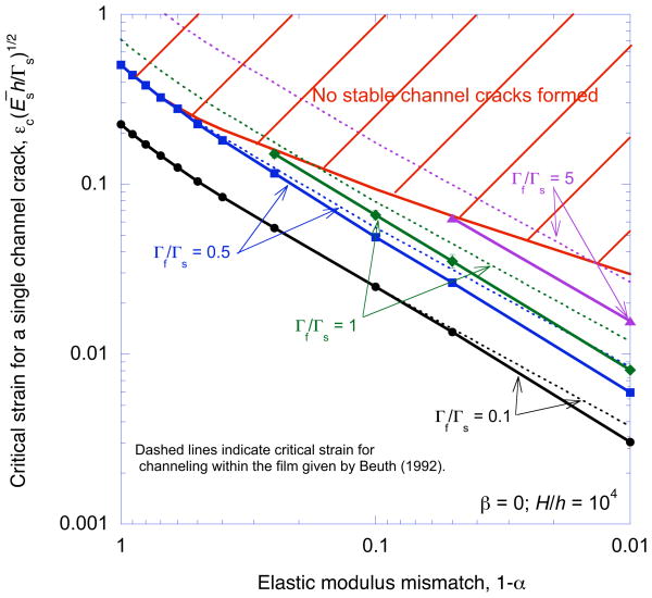
The critical strains required to propagate a single channel crack are plotted in Fig. 9 as a function of modulus mismatch for different values of Γf/Γs. Superimposed on these plots are the results from Beuth [4] for the critical strain required to channel a single crack that remains confined to the:
| (15) |
where g(α, β) can be found in Ref. [4]. For low values of Γf/Γs and α, the crack does not penetrate very far into the substrate, and Eqn. 15 provides the condition for channeling. However, as the toughness and modulus of the film increase, the penetration of the crack depth into the substrate increases. The constraint provided by the substrate is relaxed, and makes it easier for a crack to propagate. Therefore, Eqn. 15, provides an upper bound to the critical strain required for channeling. However, if the value of Γf/Γs is greater than 0.5 there are regimes of modulus-mismatch ratio for which the Eqn. 15 becomes invalid, since catastrophic failure of the substrate occurs rather than crack channeling. This regime is indicated in Fig. 9 by the limit line which shows the maximum strain that can be applied to a coated system without catastrophic failure of the substrate.
Figure 9.
A plot showing how the critical strain required for channeling a single crack across a film and substrate depends on the modulus mismatch ratio. The limit line indicates the maximum strain that can be applied to a coated system without catastrophic failure. Additionally, the results from Beuth [4] are superimposed on this plot.
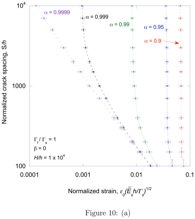
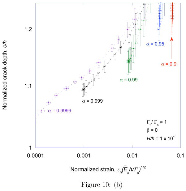
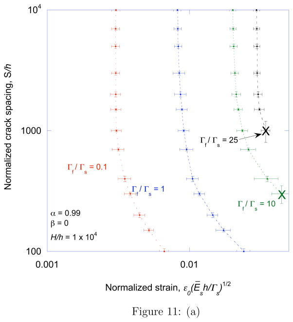
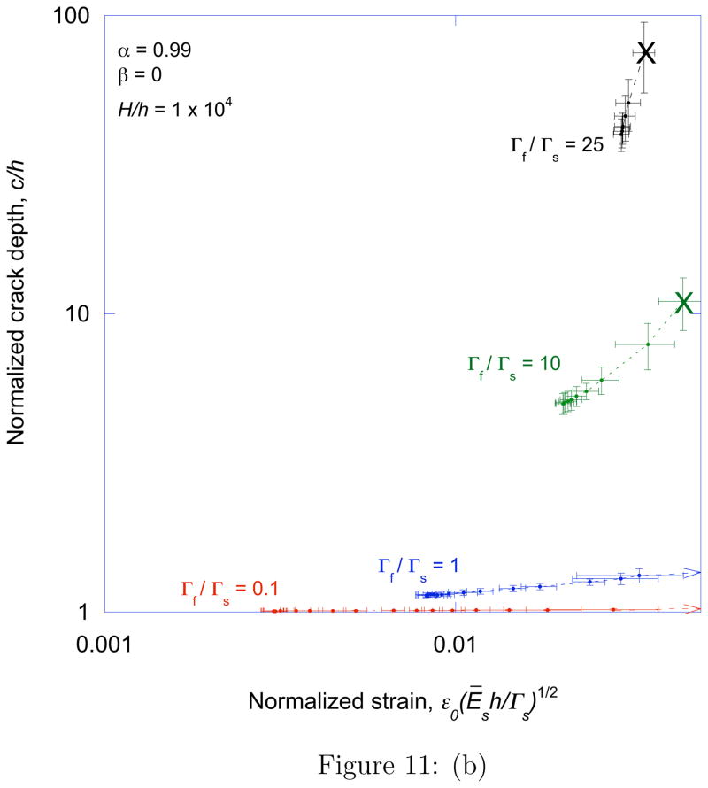
Figure 10a shows how the characteristic crack spacing varies as a function of the normalized strain for different values of α and a fixed value of Γf/Γs = 1. The corresponding depths of the arrays are shown in Fig. 10b. Similar plots are shown in Figs. 11a and 11b for a fixed value of α = 0.99 and different values of Γf/Γs. There are three distinct regimes of crack propagation. At relatively low strains, no cracks form in the system. At the critical strain required for a single crack to channel across the film and substrate, an isolated crack can channel across the film and substrate at an equilibrium depth that can be quite large for tough, stiff films. Above this critical strain a periodic crack array can develop, with a characteristic spacing that decreases with increasing strain. For very stiff films, the range of strains over which these arrays can develop is large enough to permit a regime in which the spacing decreases in an inverse linear fashion with applied strain. This behavior is consistent with the experimental observations of Ref. [12] for a system with a modulus mismatch of α ≈ 0.9999. In this regime the crack depth increases, and eventually the cracks become unstable and the substrate fails. This is of particular significance if the film is relatively tough compared to the substrate. Indeed when the toughness ratio is close to the critical value given in Fig. 8, the range of strain between the onset of channel cracking and substrate failure becomes very narrow.
Figure 10.
A plot of the (a) characteristic crack spacing and (b) crack depth as a function of normalized strain, for Γf/Γs = 1 and different values of modulus mismatch. The non-dimensional group H/h has been fixed at 104 for all the calculations in this paper, this is a reasonable approximation for a semi-infinite substrate. However, when α is as high as 0.9999, a ten-fold increase in the substrate thickness increased the crack spacing by about 10%.
Figure 11.
A plot of the (a) characteristic crack spacing and (b) crack depth as a function of normalized strain, for α = 0.99 and different values of the toughness ratio. The “X” on the plots indicates catastrophic failure of the substrate.
5 Conclusions
When a stiff film is supported on a compliant substrate, a pattern of stable periodic cracks that can be induced by the application of a remote tensile strain will channel through the substrate as well as the film. The stiffness of the film is responsible for the stability of these arrays under a remote applied tension. If the modulus mismatch is particularly extreme, for example, when a metal film is deposited on an elastomer, and the toughness of the film is relatively large, stable cracks can channel at depths that can be an order of magnitude or more deeper than the film thickness. However, some degree of substrate cracking will occur for all values of modulus mismatch with α > 0. Fracture of the substrate means that the onset of channeling occurs at strains lower than is predicted by models that limit cracking to the film, although the effect is more important for stiff, tough films. If the toughness of the film is too high relative to the toughness of the substrate, channel cracking cannot occur. Instead, the substrate fails in a catastrophic fashion without the formation of a crack array. The critical toughness value for this failure mode to occur increases with the film stiffness. However, for relatively low values of α, below about 0.71, a film that is more brittle than the substrate can trigger this failure mechanism. This may be related to the phenomenon in which stiff films appear to embrittle polymeric substrates, Above the critical strain to form a channel crack, the crack spacing decreases as the strain increases. At very high values of α, there is an approximately inverse-linear relationship between spacing and strain, as observed earlier for homogeneous systems. The depths of the cracks in these arrays increase with strain, and eventually the substrate fails in an unstable fashion.
Acknowledgments
The authors gratefully acknowledge support from the National Science Foundation (CMMI-0700232) and the National Institute of Health (R01-HG004653-01).
Footnotes
The collapse of the strain into a single non-dimensional group with the toughness is justified because the strain energy in a linear-elastic system scales with εo2
Publisher's Disclaimer: This is a PDF file of an unedited manuscript that has been accepted for publication. As a service to our customers we are providing this early version of the manuscript. The manuscript will undergo copyediting, typesetting, and review of the resulting proof before it is published in its final citable form. Please note that during the production process errors may be discovered which could affect the content, and all legal disclaimers that apply to the journal pertain.
References
- 1.Thouless MD. Crack spacing in brittle films on elastic substrates. Journal of the American Ceramic Society. 1990;73:2144–2146. [Google Scholar]
- 2.Thouless MD, Olsson E, Gupta A. Cracking of brittle films on elastic substrates. Acta Metallurgica et Materialia. 1992;40:1287–1292. [Google Scholar]
- 3.Hutchinson JW, Suo Z. Mixed mode cracking in layered materials. Advances in Applied Mechanics. 1992;29:63–191. [Google Scholar]
- 4.Beuth JL., Jr Cracking of thin films bonded in residual tension. International Journal of Solids and Structures. 1992;29:1657–1675. [Google Scholar]
- 5.Shenoy VB, Schwartzman AF, Freund LB. Crack patterns in brittle thin films. International Journal of Fracture. 2000;103:1–17. [Google Scholar]
- 6.Zak AK, Williams ML. Crack point singularities at a bi-material interface. Journal of Applied Mechanics. 1963;30:142–143. [Google Scholar]
- 7.Chen Z, Cotterell B, Wang W. The fracture of brittle thin films on complaint substrates in flexible displays. Engineering Fracture Mechanics. 2002;69:597–603. [Google Scholar]
- 8.Jansson NE, Leterrier Y, Månson JAE. Modeling of multiple cracking and decohesion of a thin film on a polymer substrate. Engineering Fracture Mechanics. 2006;73:2614–2626. [Google Scholar]
- 9.Begley MR, Bart-Smith H, Scott ON, Jones MH, Reed ML. The electro-mechanical response of elastomer membranes coated with ultra-thin metal electrodes. Journal of the Mechanics and Physics of Solids. 2005;53:2557–2578. [Google Scholar]
- 10.Gruber PA, Artz E, Spolenak R. Brittle-to-ductile transition in ultrathin Ta/Cu film systems. Journal of Materials Research. 2009;24:1906–1918. [Google Scholar]
- 11.Schalko J, Cordill MJ, Taylor A, Dehm G. Fracture and delamination of chromium thin films on polymer substrates. Metallurgical and Materials Transactions A. 2010;41A:870–874. [Google Scholar]
- 12.Douville N, Li Z, Takayama S, Thouless MD. Crack channelling in a metal-coated elastomer. 2010. Manuscript in preparation. [Google Scholar]
- 13.Pelrine R, Kornbluh R, Joseph J, Pei Q, Chiba S. High-feld deformation of elastomeric dielectrics for actuators. Materials Science and Engineering, C. 2000;11:89–100. [Google Scholar]
- 14.Begley MR, Bart-Smith H. The electro-mechanical response of highly compliant substrates and thin stiff films with periodic cracks. International Journal of Solids and Structures. 2005;42:5259–5273. [Google Scholar]
- 15.Burroughs JH, Bradley DDC, Brown AR, Marks RN, Mackay K, Friend RH, Burns PL, Holmes AB. Light-emitting diodes based on conjugated polymers. Nature. 1990;347:539–541. [Google Scholar]
- 16.Forrest SR. The path to ubiquitous and low-cost organic electronic applications on plastic. Nature. 2004;428:911–918. doi: 10.1038/nature02498. [DOI] [PubMed] [Google Scholar]
- 17.Günes S, Neugebauer H, Sariciftci NS. Comjugated polymer-based organic solar cells. Chemical Reviews. 2007;107:1324–1338. doi: 10.1021/cr050149z. [DOI] [PubMed] [Google Scholar]
- 18.Li T, Huang Z, Suo Z, Lacour SP, Wagner S. Strechability of thin metal films on elastomer substrates. Applied Physics Letters. 2004;85:3435–3437. [Google Scholar]
- 19.Lacour SP, Wagner S, Huang Z, Suo Z. Stretchable gold conductors on elastomeric substrates. Applied Physics Letters. 2003;82:2404–2406. [Google Scholar]
- 20.Lacour SP, Jones J, Suo Z, Wagner S. Design and performance of thin metal film interconnects for skin-like electronic circuits. IEEE Electron Device Letters. 2004;25:179–181. [Google Scholar]
- 21.Lewis J. Material challenge for flexible organic devices. Materials Today. 2008;9:38–45. [Google Scholar]
- 22.Chiu SL, Leu J, Ho PS. Fracture of metal-polymer line structures. I. semiflexible polyimide. Journal of Applied Physics. 1994;76:5136–5142. [Google Scholar]
- 23.Chatham H. Oxygen diffusional barrier properties of transparent oxide coatings on polymeric substrates. Surface and Coatings Technology. 1996;78:1–9. [Google Scholar]
- 24.Tsubone D, Hasebe T, Kamijo A, Hotta A. Fracture mechanics of diamond-like carbon (DLC) films coated on flexible polymer substrates. Surface and Coatings Technology. 2007;201:6423–6430. [Google Scholar]
- 25.Zhu X, Mills KL, Peters PR, Bahng JH, Liu EH, Shim J, Naruse K, Csete ME, Thouless MD, Takayama S. Fabrication of reconfigurable protein matrices by cracking. Nature Materials. 2005;4:403–406. doi: 10.1038/nmat1365. [DOI] [PubMed] [Google Scholar]
- 26.Huh D, Mills KL, Thouless MD, Takayama S. Tunable elastomeric nanochannels for nanofluidic manipulation. Nature Materials. 2007;6:424–428. doi: 10.1038/nmat1907. [DOI] [PubMed] [Google Scholar]
- 27.Mills KL, Huh D, Takayama S, Thouless MD. Instantaneous fabrication of arrays of normally closed, adjustable, and reversible nanochannels by tunnel cracking. Lab on a Chip. 2010;10:1627–1630. doi: 10.1039/c000863j. [DOI] [PubMed] [Google Scholar]
- 28.So PK, Broutman LJ. The effect of surface embrittlement on the mechanical behavior of rubber-modified polymers. Polymer Engineering and Science. 1982;22:888–894. [Google Scholar]
- 29.So PK, Broutman LJ. The fracture behavior of surface embrittled polymers. Polymer Engineering and Science. 1986;26:1173–1179. [Google Scholar]
- 30.Verpy C, Gacougnolle JL, Dragon A, Vanlerberghe A, Chesneau A, Cozette F. The surface embrittlement of a ductile blend due to a brittle paint layer. Progress in Organic Coatings. 1994;24:115–129. [Google Scholar]
- 31.Dundurs J. Edge-bonded dissimilar orthogonal elastic wedges. Journal of Applied Mechanics. 1969;36:650–652. [Google Scholar]
- 32.Vlassak JL. Channel cracking in thin films on substrates of finite thickness. International Journal of Fracture. 2003;119/120:299–323. [Google Scholar]
- 33.Huang R, Prévost JH, Huang ZY, Suo Z. Channel cracking of thin films with the extended finite-element method. Engineering Fracture Mechanics. 2003;70:2513–2526. [Google Scholar]
- 34.Ye T, Suo Z, Evans AG. Thin film cracking and the roles of substrate and interface. International Journal of Solids and Structures. 1992;29:2639–2648. [Google Scholar]
- 35.Zhang T-Y, Zhao M-H. Equilibrium depth and spacing of cracks in a tensile residual stressed thin film deposited on a brittle substrate. Engineering Fracture Mechanics. 2002;69:589–596. [Google Scholar]
- 36.Tada H, Paris PC, Irwin GR. The Stress Analysis of Cracks Handbook. 3. The American Society of Mechanical Engineers; New York, NY: 2000. [Google Scholar]
- 37.Hu MS, Thouless MD, Evans AG. The decohesion of thin films from brittle substrates. Acta Metallurgica. 1988;36:1301–1307. [Google Scholar]


