Abstract
Fluorescence imaging is used to study the dynamics of a wide variety of single molecules in solution or attached to a surface. Two key challenges in this pursuit are (1) to image immobilized single molecules in the presence of a high level of fluorescent background and (2) to image freely diffusing single molecules for long times. Strategies that perform well by one measure often perform poorly by the other. Here, we present a simple modification to a wide-field fluorescence microscope that addresses both challenges and dramatically improves single-molecule imaging. The technique of convex lens-induced confinement (CLIC) restricts molecules to a wedge-shaped gap of nanoscale depth, formed between a plano-convex lens and a planar coverslip. The shallow depth of the imaging volume leads to 20-fold greater rejection of background fluorescence than is achieved with total internal reflection fluorescence (TIRF) imaging. Elimination of out-of-plane diffusion leads to an approximately 10 000-fold longer diffusion-limited observation time per molecule than is achieved with confocal fluorescence correlation spectroscopy. The CLIC system also provides a new means to determine molecular size. The CLIC system does not require any nanofabrication, nor any custom optics, electronics, or computer control.
Single-molecule spectroscopy (SMS) provides information on the distribution of microstates and transitions of a wide variety of biomolecules. Fundamental insights into molecular biophysics have been obtained through this suite of techniques.1 However, technical limitations prevent application of SMS to many types of processes. Particularly challenging are processes that involve (1) weak intermolecular interactions or (2) slow dynamics. Weak or cooperative interactions typically require at least one species to be at micromolar or higher concentration, but far-field techniques cannot resolve fluorescent single molecules at concentrations higher than approximately 100 nM. Slow processes require long observation times, but surface immobilization often disrupts molecular structure or dynamics; freely diffusing molecules are typically observed for <1 ms.
The goals of imaging in the presence of background fluorescence and imaging in solution for long times are often seen as being in tension with each other. An approximate criterion for distinguishing a single fluorophore above background is that there should be no more than one fluorophore, on average, within a detection volume. Techniques with a smaller detection volume can detect single molecules in the presence of a higher background concentration. Among common imaging techniques, the maximum concentrations for detecting single molecules are ranked: zero-mode waveguides2 > total internal reflection fluorescence (TIRF)3 > confocal > epifluorescence. (See Table 1.) However, a smaller detection volume leads to a shorter diffusion-limited transit time. The observation times for freely diffusing molecules in these same imaging techniques are ranked: epifluorescence > confocal > TIRF > zero-mode waveguides.
Table 1.
Comparison of Single-Molecule Imaging Techniquesa
| imaging modality | dimensions of imaging volume L×W×H (μm3) | maximum concentration of single molecules | observation time (D = 100 μm2/s) | number of single molecules observed simultaneously |
|---|---|---|---|---|
| TIRF | 100 × 100 × 0.1 | 110 nM | 500 μs (vertical) | hundreds |
| confocal | 0.3 × 0.3 ×1 | 10 nM | 200 μs (in-plane) | one |
| zero-mode waveguides | 0.04 × 0.04 × 0.02 | 50 μM | 2μs (vertical) | one per waveguide |
| ABEL trap | 3 × 3 × 0.8 | 200 pM | 2 s (photobleaching) | one |
| CLIC | 100 × 100 × 0.005 | 2 μM | 25 s (in-plane) | hundreds |
TIRF and CLIC are wide-field techniques that allow imaging of many molecules simultaneously. Zero-mode waveguides can be imaged individually or in an array format. The concentration limit on single-molecule detection is estimated at one molecule in the smaller of the imaging volume or the diffraction-limited point spread function. Numbers are approximate. The parameter limiting the observation time is given in parentheses after the time. Vertical: diffusion perpendicular to the imaging plane. In-plane: diffusion within the imaging plane. The ABEL trap requires high count rates per fluorophore, typically 50–70 kHz, to provide the tracking signal needed for real-time feedback on single fluorophores. The ABEL trap cannot trap single fluorophores at lower count rates because the tracking becomes so uncertain that the molecule can escape from the trap. In the CLIC device, one can make a trade-off between excitation intensity (and hence photobleaching rate) and tracking precision. It is often advantageous to use a lower count rate per fluorophore in CLIC than is needed in the ABEL trap.
A strategy to circumvent this trade-off is to immobilize single molecules in confined volumes without direct surface attachment. This idea has been applied to study single molecules in liposomes,4,5 water-in-oil emulsions,6 nanofabricated devices,7 and the anti-Brownian electrokinetic trap (ABEL trap),8,9 but these systems are complex to build and operate.
We developed a simple device that dramatically improves imaging of single biomolecules. The device improves background rejection when imaging surface-immobilized molecules, and it increases observation time when imaging freely diffusing molecules. The convex lens-induced confinement (CLIC) system restricts molecules to a fluid film with nanometer dimensions perpendicular to the imaging plane. The confinement reduces the vertical dimension of the imaging volume and, thereby, improves background rejection. The confinement also keeps freely diffusing single molecules in the focal plane of the microscope and, thereby, increases imaging time. Additionally, one can use the CLIC system to determine the size of macromolecules because macromolecules are excluded from regions where the molecular diameter is larger than the depth of confinement.
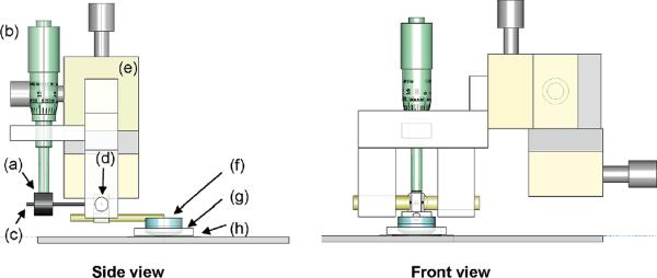
In its simplest incarnation, the CLIC device consists of a plano-convex lens, curved side down, resting on top of a coverslip (Figure 1). The region surrounding the point of contact is imaged in an inverted fluorescence microscope. The lens-coverslip gap height varies smoothly from zero at the point of contact, to hundreds of micrometers at positions far from the point of contact, according to
| (1) |
where r is the distance from the point of contact and R is the radius of curvature of the lens (Figure 2a). This simple formula agrees quantitatively with in situ calibration (see Supporting Information Method 6). For example, in a 100 μm × 100 μm field of view centered on the point of contact, with a 100 mm focal length lens (R = 46 mm), the gap varies from 0 to 27 nm. Optical measurements at a series of points spaced by micrometers lead to information on molecular properties at a series of confinements spaced by nanometers.
Figure 1.
Schematic of the CLIC device. The side view and front view show (a) counterweight, (b) micrometer, (c) rod, (d) jewel bearing, (e) XYZ translation stage, (f) optical flat and lens, (g) PDMS gasket, and (h) coverslip.
Figure 2.
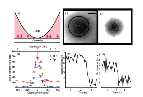
CLIC measurements of immobilized fluorescent objects in the presence of freely diffusing fluorophores. (a) Schematic of sample geometry. (b) Signal-to-background ratio as a function of displacement from the point of contact for surface-immobilized fluorescent polystyrene beads of diameter 36 nm, immersed in 50 nM Alexa 647, λexc = 633 nm. (See Supporting Information Method 1.) CLIC image of surface-tethered DNA oligonucleotides in the presence of (c) 0.2 μM and (d) 2 μM Alexa 647. Scale bar 10 μm. Black contour indicates hCLIC = 2 nm. Different contrasts are applied to the two images to permit visualization of the single molecules near the center and the background in the surround. At 2 μM Alexa 647, single oligos may be detected within a disk of radius r = 16 μm, corresponding to hCLIC = 3 nm, in agreement with the expected detection limit. (e) and (f) photobleaching timetraces of single molecules from (c) and (d), respectively.
We constructed an apparatus in which a micrometer and jewel bearing are used to raise and lower a lens from a coverslip surface in a controlled manner. We present single-molecule measurements that demonstrate the capabilities of the CLIC device. These include: (a) measurements on single immobilized molecules in the presence of a high concentration of freely diffusing fluorescent molecules; (b) counting of transmembrane proteins in freely diffusing lipid vesicles; and (c) direct mechanical measurements of size and compressibility of double stranded DNA.
EXPERIMENTAL SECTION
Construction of the CLIC Device
The CLIC device is designed to bring the lens into gentle contact with the coverslip, while minimizing fluid shear and flexure of the coverslip (Figure 1). A stainless steel rod is glued to extend radially from the edge of a convex lens (ThorLabs LA 4600, LA 4765, or LA 4936, R = 46, 23, and 13.8 mm, respectively). The rod pivots about a horizontal axis on a pair of jewel bearings (Small Parts VJPX-7D-01; VJA-7-01). The distal end of the rod contains a counterweight to minimize the force of the lens on the coverslip. A micrometer is positioned to push down on the counterweight, raising or lowering the lens. The entire assembly is mounted on an XYZ translation stage (Thorlabs DT12). The liquid sample is placed on a fused silica coverslip (Esco R425025 S1-UV) and contained by an annular PDMS gasket.
Surface Coatings to Prevent Nonspecific Adsorption
The surfaces of the lens and coverslip are passivated in one of several ways to prevent nonspecific molecule–surface interactions. In studying nucleic acids, we preincubate the lens and coverslip surfaces with a 1% solution of polyvinylpyrrolidone (PVP; MW 1.3 MDa; Sigma-Aldrich 437190) for 20 min. In studying diffusing lipid vesicles, we preincubate the surfaces with unlabeled vesicles to form a lipid bilayer. In studying proteins, we coat the surfaces with polyethylene glycol (PEG; Vectabond Reagent SP-1800 and MPEG-SVA-5000, Laysan Bio Inc.), following the manufacturer's procedure. In addition, we use a buffer in which unlabeled bovine serum albumin (BSA) has been dissolved at 0.4% by mass. In each case, we flow buffer through the CLIC system following the surface passivation step. It is crucial to keep the lens and coverslip wet throughout the measurement.
Operation of the CLIC Device
The x and y axes of the translation stage are used to position the lens in the field of view of the microscope. The counterbalance is adjusted so the freely pivoting lens is slightly forward weighted, to ensure good lens–coverslip contact. Beginning with a clean, dry coverslip, the z translation axis is lowered until the lens makes contact with the coverslip. Next, the micrometer is adjusted to raise the lens. The sample is pipetted slowly onto the coverslip so that it flows between the lens and coverslip. Finally, the micrometer is adjusted to lower the lens slowly onto the coverslip.
Multiple measurements of the same sample may be performed by raising the lens slightly with the micrometer, adjusting the x and y translation axes, and relowering the lens. If part of the lens surface becomes contaminated by adsorbed molecules, fresh regions of the lens surface may be brought into contact with the coverslip by slightly rotating the lens-holding rod.
Fluorescence images are acquired using an inverted epifluorescence microscope (Olympus IX71), a 60× oil-immersion objective (N.A. 1.45, Olympus 1-U2B616), and an EMCCD camera (512 × 512 CCD with 16 μm pixels, Andor iXon DU-897E-CS0-#BV). The lens–coverslip point of contact is determined by illuminating the sample with white light and imaging Newton's rings, formed by the interference of light reflected from the lens and coverslip surfaces. In each experiment, a series of images at different positions under the lens is acquired using a motorized translation stage.
RESULTS
Measurements of Single Immobilized Molecules in the Presence of a High Background Concentration of Freely Diffusing Fluorophores
TIRF provides the smallest detection volume of the conventional far-field imaging techniques. The depth of this volume is hTIRF ≈ λ/2π, where λ is the excitation wavelength, and the lateral dimensions are set by the diffraction limit of the objective.3 In a typical setup with illumination at λ = 633 nm and an objective with numerical aperture NA = 1.45, hTIRF ≈ 100 nm, and single-molecule detection is possible up to a background concentration nM.10
In the CLIC system, the depth of the imaging volume is given by eq 1. Near the point of contact, hCLIC < hTIRF. Therefore, single immobilized molecules can be detected against a higher background concentration of fluorophores by CLIC than by the other far-field techniques (Table 1).
We demonstrate this improved rejection of background by comparing images taken with CLIC to images taken with TIRF (Figure 2). As a model system, we use DNA oligonucleotides labeled with a single fluorophore and immobilized on a coverslip, imaged in the presence of a variable concentration of free dye. (See Supporting Information Method 2.) Figure 2 shows that detection of single immobilized molecules is possible up to a background concentration of free dye μM, 20-fold higher than . Single molecules are only visible where the lens confines the solution to a sufficiently thin depth that background molecules do not contribute substantially to the observed signal.
Long-Time Observation of Single Freely Diffusing Fluorescent Particles
Surface immobilization allows long-time observation of single molecules,4,5,11–13 but may disrupt molecular function and misses the information on particle size that is encoded in diffusive trajectories. By restricting diffusion to a quasi-planar gap whose height is less than the focal depth, CLIC enables freely diffusing molecules to be observed for times limited either by photobleaching or by lateral diffusion out of the field of view. In CLIC, a molecule must diffuse ~100 μm to exit the field of view, while in TIRF and confocal fluorescence correlation spectroscopy (FCS) the molecule need only diffuse <1 μm to escape the detection volume. This difference in diffusion distances leads to diffusion-limited observation times ~104-fold longer in CLIC than achieved by TIRF or FCS (Table 1). Due to the in-plane confinement, CLIC is restricted to liquid and quasi-planar samples, while FCS and other confocal techniques can probe extended three-dimensional objects.
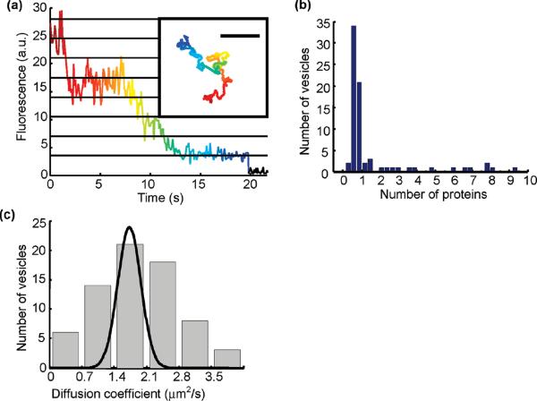
We used CLIC to observe freely diffusing lipid vesicles containing a small number of fluorescently labeled transmembrane proteins. Blue-absorbing proteorhodopsin (BPR) singly labeled with Atto 647N was inserted at low copy number into vesicles of diameter d = 180 ± 40 nm, determined by dynamic light scattering. (See Supporting Information Method 3.) The diffusive trajectories of n = 70 vesicles were followed for times up to 25 s, limited by photobleaching (Figure 3a and Supporting Information Movie 1), using custom particle-tracking software (See Supporting Information Method 4.) By counting the number of photobleaching steps, we determined the number of proteins in each vesicle (Figure 3b). The large peak at single occupancy establishes that BPR inserts into vesicles as a monomer.
Figure 3.
Long-time observation of freely diffusing lipid vesicles containing fluorescently labeled BPR. (a) Time-resolved intensity of a tracked vesicle. Each point represents the time average of three consecutive exposures with texp = 0.03 s. The intensity of a single fluorophore was determined from the population average of the amplitude of the last photobleaching event. Horizontal lines indicate integer multiples of the photobleaching step size. Inset: trajectory of the same vesicle, characterized by D = 1.6 ± 0.2 μm2/s (colored according to time). Scale bar 10 μm. (b) Histogram of the number of BPR monomers per vesicle. The BPR count was determined by dividing the initial fluorescence intensity of each vesicle by the intensity of one fluorophore. Most vesicles contain 0 or 1 BPR copies, establishing that the proteins are inserted into the vesicles as monomers. Imperfect measurement of the initial intensity leads to noninteger estimates for the number of proteins at high occupancy. (c) Histogram of diffusion coefficients of 70 vesicles. The gap height was between 450 nm and 1.4 μm. The broad distribution is dominated by heterogeneity in vesicle size. The superimposed Gaussian (unnormalized) shows the per-vesicle uncertainty in D due to finite-length trajectories.
The distribution of single-vesicle diffusion coefficients (Figure 3c) is peaked at D = 1.8 μm2/s, consistent with the value D = 2 μm2/s reported by dynamic light scattering. The distribution shows significant broadening beyond the Gaussian spread expected from finite sampling of diffusive trajectories. To estimate the expected variation in D due to hydrodynamic coupling to the walls, we used the theory and experiment of Facheaux and Libchaber for diffusion of a spherical particle between planar walls.14 At the 450 nm-thick edge of the field of view, their results imply that D is approximately 60% of the bulk value, while on the 1.5 μm side D is 80% of bulk. Due to sampling bias toward the thicker side, we expect hydrodynamic wall coupling to contribute a variation of less than 25% over the field of view.
Direct Mechanical Measurement of Molecular Size and Compressibility
One often wishes to determine the size of a molecule or, more generally, the distribution of sizes in an ensemble of molecules. CLIC provides an alternative to conventional methods such as gel electrophoresis, dynamic light scattering, and fluorescence correlation spectroscopy and avoids some of the limitations of these techniques.
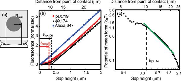
Molecules are physically excluded from regions in which the gap height is less than the molecular diameter. This exclusion is employed to determine the molecular size. For a sample of monodisperse hard spheres of diameter d, a fluorescent image centered on the point of contact shows a disk inside of which there is no fluorescence (Figure 4a). At the boundary of this disk, the gap height h = d. One measures the radius, r, of the excluded disk and, from the known dependence of h on r, determines d. This principle has previously been applied to determine the sizes of micrometer-scale particles.15
Figure 4.
Measuring the size of DNA molecules and the potential of mean force for confinement. (a) Schematic showing a disk centered on the point of contact inside of which molecules are excluded and there is little fluorescence. The molecular diameter is determined from the radius of this excluded region, Rexcl, and the geometry of the lens. (b) Normalized fluorescence profiles of solutions of two lengths of linear DNA, pUC19 (2.7 kbp) and ϕX174 (5.4 kbp) (C0 = 1.4 nM for each), and free Alexa 647 dye (C0 = 50 nM). Linear fits to these profiles are performed at gap heights 0.6 μm < h < 2.7 μm. The fluorescence profiles have been background-subtracted and normalized to have equal slopes in this region. (c) Potential of mean force for confinement of linear ϕX174 DNA, determined from the depth-dependent concentration profile.
We apply this principle to determine the diameter of nano-meter-scale plasmid DNA and protein molecules. (See Supporting Information Method 5.) The spatial profile of fluorescence, I, is related to the projected areal concentration of molecules, Σ, by I = B0Σ where B0 is a constant dependent on excitation power, labeling density, photophysical properties of the fluorophore, and optical collection efficiency. The procedure for extracting I(h) from images is given in Supporting Information Method 6. Figure 4b shows fluorescence vs gap height, I(h), for linearized plasmids labeled with the intercalating dye YOYO-1. At large gaps, I is a linear function of h (provided that h is smaller than the depth of focus). A fit to this linear region is extrapolated down to the h-intercept. The value of h at the intercept yields an effective molecular diameter, δ = 0.38 ± 0.04 μm for ϕX174 and δ = 0.30 ± 0.06 μm for pUC19. These values are in good agreement with the predicted diameters of gyration dgyr = 0.40 μm for ϕX174 and 0.26 μm for pUC19, calculated using ref 16.
In contrast to the sharp cutoff at small h expected for hard spheres, the intensity profile of the DNA samples has a gradual cutoff, with many molecules diffusing into regions with h < δ. DNA can adopt many conformations, some of which are thin enough to enter the “excluded region”; however, such conformations are entropically disfavored.
The free energy to transfer molecules into the gap from the bulk determines the areal density profile of the molecules. The density profile is Σ = C0h exp(−U(h)/kBT), where C0 is the bulk concentration, kB is the Boltzmann constant, T is the absolute temperature, and U(h) is the potential of mean force, closely related to the free energy. (See Supporting Information Discussion 1.) We apply this concept to measure U(h) of linearized plasmid DNA (Figure 4c). Rearranging the expression for the Boltzmann factor yields
| (2) |
The second term on the right-hand side is an additive constant and is obtained by setting U(h) → 0 at large h. Thus, it is not necessary to know the constants B0 or C0.
U(h) is predicted to follow a scaling relation U(h)/kBT ~ (Rg/h)q. For ideal noninteracting chains, q = 2,17 while polymer-surface attraction is expected to lower the value of q.18 We measure q = 1.3 ± 0.3 in the weak confinement regime (h≥δ) for ϕX174 (Figure 4c).
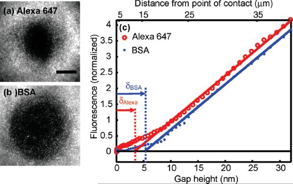
Interactions with the surface can bias the measurement of the molecular diameter by introducing additional spatially varying components to U(h). These interactions may be minimized by coating the surfaces with adsorption-resisting layers, such as PEG, BSA, or lipid bilayers. Operation at high ionic strength minimizes electrostatic interactions,19 although some intermolecular interactions are disrupted at high salt concentration. Surface interactions introduce the largest bias to estimates of molecular size when the range of the interaction is comparable to the size of the molecules. For example, images of a mixture of free Alexa 647 (d ~ 1 nm) and BSA labeled with Alexa 488 (d ~ 3 nm) show a larger excluded disk for the BSA than for the Alexa 647, as expected (Figure 5a,b). However, the molecular diameters determined via CLIC (δBSA = 5.2 ± 4 nm; δAlexa = 3.4 ± 3 nm) are larger than the true molecular diameters (Figure 5c). Thus, for molecules in the low nanometer range, CLIC provides a qualitative measure of relative size and, at present, not a quantitative measure of absolute size.
Figure 5.
Measuring the size of small molecules by their physical exclusion. Fluorescence images of (a) Alexa 647 (d ~ 1 nm; C0 = 50 nM) and (b) BSA labeled with Alexa 488; (d ~ 3 nm; C0 = 300 nM) under the same conditions. The BSA is excluded from a larger region than is the free dye. Scale bar 20 μm. (c) Normalized fluorescence profiles of BSA from (c) and a separate measurement of Alexa 647. Linear fits to I(h) performed at h > 10 nm yield δBSA = 5.2 ± 4 nm and δAlexa= 3.4 ± 3 nm.
The accuracy of a size measurement is limited by how well the curvature of the lens is known. This curvature can be measured in situ using optical interferometry. (See Supporting Information Method 6.) The precision of the measurement is limited by the surface roughness of the lens and the coverslip. Fused silica optics are commercially available with rms surface roughness <1 nm.
DISCUSSION
The CLIC system facilitates new biophysical measurements by providing improved background rejection and extended observation time. For instance, CLIC may enable single-molecule studies of interactions between surface-bound receptors and freely diffusing ligands with Kd values up to several μM. Long-time observations of lipid vesicles allow counting of fluorescently labeled components by the number of photobleaching steps. Deviations from Poisson statistics indicate interactions among these components. Such counting could be applied to clathrin around endocytic vesicles,20 to determine the stoichiometry of transmembrane complexes,21,22 and to study the composition of synaptic vesicles.
The graded confinement of CLIC provides insights into the coupling between molecular geometry and chemical function. Simultaneous imaging of freely diffusing protein and DNA molecules could resolve protein–DNA binding and the resulting changes in the diameter of the DNA polymer coil.23 Force–extension curves of DNA have been studied extensively;24 CLIC probes the force–compression curve which is much less under-stood. The latter quantity is relevant to packaging of DNA in cells and viruses. CLIC may also enable measurements of interactions between surface-bound and free molecules as a function of molecular confinement, for instance, mimicking ligand-receptor binding in synapses and intercellular junctions.
Several related approaches have been developed to study molecules in confinement. The surface force apparatus (SFA) has been widely applied to study the mechanical properties of molecules in nanoscale gaps.25 While CLIC does not directly measure forces in the gap, it complements the SFA by providing sensitive optical access, enabling measurements of molecular conformations, dynamics, and diffusion. Nanofabricated slits and wedges are also used to study molecules confined to planar gaps.26–28 These chips are appropriate for portable device applications, but the CLIC approach is simpler to implement in a laboratory setting and avoids the laborious steps of microfabrication. Finally, a device with a geometry similar to CLIC has been used to study quantum electrodynamic effects on the fluorescence of dye molecules in reflective nanocavities.29
Supplementary Material
ACKNOWLEDGMENT
We thank Paul Handorff for technical assistance, Halil Bayraktar and Joel Kralj for preparation of fluorescently labeled lipid vesicles, Amy Xu for a sample of fluorescently labeled BSA, Min Ju Shon for help constructing the apparatus, and Jennifer Hou for help with particle tracking. This work was supported by a Mary Fieser Postdoctoral Fellowship (S.R.L.), NSF Grant CHE-0910824, and the Materials Research Science and Engineering Center (MRSEC) of Harvard University under NSF Grant DMR-0820484.
Footnotes
SUPPORTING INFORMATION AVAILABLE Additional information as noted in text. This material is available free of charge via the Internet at http://pubs.acs.org.
References
- (1).Selvin PR, Ha T. Single Molecule Techniques: A Laboratory Manual. First ed. Cold Spring Harbor Laboratory Press; New York: 2008. [Google Scholar]
- (2).Levene MJ, Korlach J, Turner SW, Foquet M, Craighead HG, Webb WW. Science. 2003;299:682–686. doi: 10.1126/science.1079700. [DOI] [PubMed] [Google Scholar]
- (3).Axelrod D. Traffic. 2001;2:764–774. doi: 10.1034/j.1600-0854.2001.21104.x. [DOI] [PubMed] [Google Scholar]
- (4).Boukobza E, Sonnenfeld A, Haran G. J. Phys. Chem. B. 2001;105:12165–12170. [Google Scholar]
- (5).Okumus B, Arslan S, Fengler SM, Myong S, Ha T. J. Am. Chem. Soc. 2009;131:14844–14844. doi: 10.1021/ja9042356. [DOI] [PMC free article] [PubMed] [Google Scholar]
- (6).Chiu DT, Lorenz RM, Jeffries GDM. Anal. Chem. 2009;81:5111–5118. doi: 10.1021/ac900306q. [DOI] [PMC free article] [PubMed] [Google Scholar]
- (7).Levy SL, Craighead HG. Chem. Soc. Rev. 2010;39:1133–1152. doi: 10.1039/b820266b. [DOI] [PubMed] [Google Scholar]
- (8).Cohen AE, Moerner WE. Proc. Natl. Acad. Sci. U.S.A. 2006;103:4362–4365. doi: 10.1073/pnas.0509976103. [DOI] [PMC free article] [PubMed] [Google Scholar]
- (9).Cohen AE, Moerner WE. Opt. Express. 2008;16:6941–6956. doi: 10.1364/oe.16.006941. [DOI] [PMC free article] [PubMed] [Google Scholar]
- (10).Hassler K, Leutenegger M, Rigler P, Rao R, Rigler R, Gösch M, Lasser T. Opt. Express. 2005;13:7415–7423. doi: 10.1364/opex.13.007415. [DOI] [PubMed] [Google Scholar]
- (11).Kuzmenkina EV, Heyes CD, Nienhaus GU. Proc. Natl. Acad. Sci. U.S.A. 2005;102:15471–15476. doi: 10.1073/pnas.0507728102. [DOI] [PMC free article] [PubMed] [Google Scholar]
- (12).Abbondanzieri EA, Bokinsky G, Rausch JW, Zhang JX, Le Grice SFJ, Zhuang X. Nature. 2008;453:184–189. doi: 10.1038/nature06941. [DOI] [PMC free article] [PubMed] [Google Scholar]
- (13).Vale RD, Milligan RA. Science. 2000;288:88–95. doi: 10.1126/science.288.5463.88. [DOI] [PubMed] [Google Scholar]
- (14).Faucheux LP, Libchaber AJ. Phys. Rev. E. 1994;49:5158–5163. doi: 10.1103/physreve.49.5158. [DOI] [PubMed] [Google Scholar]
- (15).Hatta M, Monjushiro H, Watarai H. Chem. Commun. 2004;2004:2772–2773. doi: 10.1039/b411995a. [DOI] [PubMed] [Google Scholar]
- (16).Smith DE, Perkins TT, Chu S. Macromolecules. 1996;29:1372–1373. [Google Scholar]
- (17).de Gennes PG. Scaling Concepts in Polymer Physics. First ed. Cornell Univ. Press; Ithaca, NY: 1979. [Google Scholar]
- (18).Cifra P, Bleha T. Macromolecules. 2001;34:605–613. [Google Scholar]
- (19).Israelachvili JN. Intermolecular and Surface Forces. Third ed. Academic Press; London: 1992. [Google Scholar]
- (20).Moskowitz HS, Yokoyama CT, Ryan TA. Mol. Biol. Cell. 2005;16:1769–1776. doi: 10.1091/mbc.E04-08-0739. [DOI] [PMC free article] [PubMed] [Google Scholar]
- (21).Song L, Hobaugh MR, Shustak C, Cheley S, Bayley H, Gouaux JE. Science. 1996;274:1859–1865. doi: 10.1126/science.274.5294.1859. [DOI] [PubMed] [Google Scholar]
- (22).MacKinnon R. Nature. 1991;350:232–235. doi: 10.1038/350232a0. [DOI] [PubMed] [Google Scholar]
- (23).Zhang J, McCauley MJ, Maher LJ, Williams MC, Israeloff NE. Nucleic Acids Res. 2009;37:1107–1114. doi: 10.1093/nar/gkn1011. [DOI] [PMC free article] [PubMed] [Google Scholar]
- (24).Bustamante C, Bryant Z, Smith SB. Nature. 2003;421:423–427. doi: 10.1038/nature01405. [DOI] [PubMed] [Google Scholar]
- (25).Klein J, Kumacheva E. J. Chem. Phys. 1998;108:6996–7009. [Google Scholar]
- (26).Reisner W, Morton KJ, Riehn R, Wang YM, Yu Z, Rosen M, Sturm JC, Chou SY, Frey E, Austin RH. Phys. Rev. Lett. 2005;94:196101. doi: 10.1103/PhysRevLett.94.196101. [DOI] [PubMed] [Google Scholar]
- (27).Hsieh CC, Balducci A, Doyle PS. Nano Lett. 2008;8:1683–1688. doi: 10.1021/nl080605+. [DOI] [PubMed] [Google Scholar]
- (28).Stavis SM, Strychalski EA, Gaitan M. Nanotechnology. 2009;20:165302. doi: 10.1088/0957-4484/20/16/165302. [DOI] [PubMed] [Google Scholar]
- (29).Chizhik A, Schleifenbaum F, Gutbrod R, Chizhik A, Khoptyar D, Meixner AJ, Enderlein J. Phys. Rev. Lett. 2009;102:073002. doi: 10.1103/PhysRevLett.102.073002. [DOI] [PubMed] [Google Scholar]
Associated Data
This section collects any data citations, data availability statements, or supplementary materials included in this article.


