Abstract
Purpose: Using magnetic resonance imaging (MRI) for real-time guidance during radiotherapy is an active area of research and development. One aspect of the problem is the influence of the MRI scanner, modeled here as an external magnetic field, on the medical linear accelerator (linac) components. The present work characterizes the behavior of two medical linac electron guns with external magnetic fields for in-line and perpendicular orientations of the linac with respect to the MRI scanner.
Methods: Two electron guns, Litton L-2087 and Varian VTC6364, are considered as representative models for this study. Emphasis was placed on the in-line design approach in which case the MRI scanner and the linac axes of symmetry coincide and assumes no magnetic shielding of the linac. For the in-line case, the magnetic field from a 0.5 T open MRI (GE Signa SP) magnet with a 60 cm gap between its poles was computed and used in full three dimensional (3D) space charge simulations, whereas for the perpendicular case the magnetic field was constant.
Results: For the in-line configuration, it is shown that the electron beam is not deflected from the axis of symmetry of the gun and the primary beam current does not vanish even at very high values of the magnetic field, e.g., 0.16 T. As the field strength increases, the primary beam current has an initial plateau of constant value after which its value decreases to a minimum corresponding to a field strength of approximately 0.06 T. After the minimum is reached, the current starts to increase slowly. For the case when the beam current computation is performed at the beam waist position the initial plateau ends at 0.016 T for Litton L-2087 and at 0.012 T for Varian VTC6364. The minimum value of the primary beam current is 27.5% of the initial value for Litton L-2087 and 22.9% of the initial value for Varian VTC6364. The minimum current is reached at 0.06 and 0.062 T for Litton L-2087 and Varian VTC6364, respectively. At 0.16 T the beam current increases to 40.2 and 31.4% from the original value of the current for Litton L-2087 and Varian VTC6364, respectively. In contrast, for the case when the electron gun is perpendicular to the magnetic field, the electron beam is deflected from the axis of symmetry even at small values of the magnetic field. As the strength of the magnetic field increases, so does the beam deflection, leading to a sharp decrease of the primary beam current which vanishes at about 0.007 T for Litton L-2087 and at 0.006 T for Varian VTC6364, respectively. At zero external field, the beam rms emittance computed at beam waist is 1.54 and 1.29π-mm-mrad for Litton L-2087 and Varian VTC6364, respectively. For the in-line configuration, there are two particular values of the external field where the beam rms emittance reaches a minimum. Litton L-2087 rms emittance reaches a minimum of 0.72π and 2.01π-mm-mrad at 0.026 and 0.132 T, respectively. Varian VTC6364 rms emittance reaches a minimum of 0.34π and 0.35π-mm-mrad at 0.028 and 0.14 T, respectively. Beam radius dependence on the external field is shown for the in-line configuration for both electron guns.
Conclusions: 3D space charge simulation of two electron guns, Litton L-2087 and Varian VTC6364, were performed for in-line and perpendicular external magnetic fields. A consistent behavior of Pierce guns in external magnetic fields was proven. For the in-line configuration, the primary beam current does not vanish but a large reduction of beam current (up to 77.1%) is observed at higher field strengths; the beam directionality remains unchanged. It was shown that for a perpendicular configuration the current vanishes due to beam bending under the action of the Lorentz force. For in-line configuration it was determined that the rms beam emittance reaches two minima for relatively high values of the external magnetic field.
Keywords: MRI-linac, electron gun, space charge simulation
INTRODUCTION
The ideal image guidance strategy in radiation therapy is to have real-time volumetric and position information of the tumor and surrounding healthy tissue during the treatment itself. This information will enable continuous alignment of the therapeutic radiation beam with the tumor to facilitate local control while simultaneously avoiding the overdosing of critical structures. One compelling approach is to use magnetic resonance imaging (MRI), which is a noninvasive technique that not only allows real-time volumetric imaging but also provides exquisite soft tissue contrast to differentiate cancerous from healthy tissue.
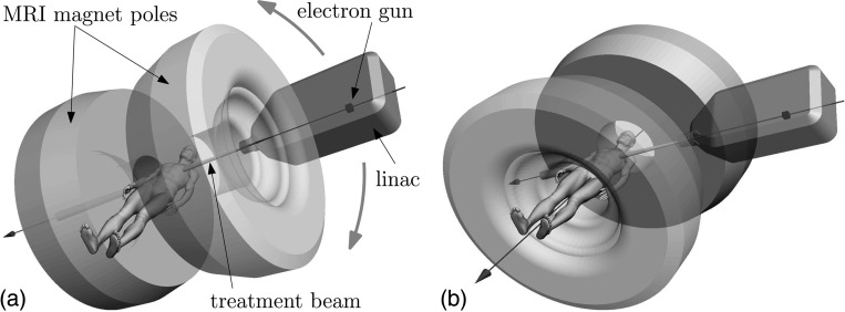
Both the linac and the MRI scanner use electromagnetic fields to function and placing these systems in close proximity may cause interactions which could influence the functionality of the two systems.1, 2 The focus of this study is to characterize the behavior of the electron gun of the linac in the absence of any magnetic shield for two orientations relative to the magnetic field of the MRI scanner, in-line and perpendicular as shown in Fig. 1.
Figure 1.
(a) Schematic representation of the proposed in-line MRI-linac apparatus. The treatment beam is in-line with the main magnetic field of the MRI magnet. The patient is positioned between the poles of the MRI magnet in a perpendicular position with respect to the main magnetic field and the treatment beam. The whole MRI-linac apparatus should rotate around the patient superior–inferior axis such that the main magnetic field of the MRI scanner and the treatment beam remain in-line, although the patient could alternatively be rotated in a sitting or lying position. (b) Schematic representation of a possible perpendicular MRI-linac configuration. The treatment beam is perpendicular to the main magnetic field of the MRI scanner. In this case the linac can rotate around the main axis of the MRI machine.
Investigations similar to the present work were performed by other groups. These studies present an electron gun model based on electron beam electric current measurements3 and simulations in external magnetic fields performed for both in-line4 and perpendicular5 configurations. A sensitivity analysis was presented on how the electron gun beam characteristics changed with certain geometrical features of the focusing electrode.3 In addition to the electron gun studies in external fields, investigations of a waveguide model6 and dosimetry in a water tank were performed in an external magnetic field for both in-line4 and perpendicular5 configurations. Also, realistic lung dosimetric studies were recently reported7 for both in-line and perpendicular configurations, which shed more light on the potential benefits of an in-line configuration.
This work involves two different models based on Litton L-2087 and Varian VTC6364 electron guns for which an almost complete set of geometrical and physical parameters are known.8 This study is motivated by the proposal of an in-line MRI-linac configuration composed of an open bore superconducting magnet and a linac with no magnetic shielding. The absence of a magnetic shield for the linac required a preliminary study regarding the behavior of these electron guns in the presence of external magnetic fields. Based on the results regarding electron beam current dependence on the external field and on previous publications,4, 5 it was found that Pierce type electron guns exhibits a consistent behavior, which is an original finding of this work. A set of novel results are reported which include the beam radius, the beam emittance, and the Courant–Snyder alpha parameter dependence on the external field for the in-line configuration. Also, an analysis of three different thermionic emission models at zero magnetic field is presented. The present work also shows a novel and direct way to implement realistic magnetic fields in electron gun simulations based on 3D field maps obtained with input from experimental measurements.
The geometries of the MRI magnet and the linac constrain their possible relative orientations. One solution places the linac and the MRI machines such that the electron beam path and the main field of the MRI system are in-line.4, 7, 9, 10, 11 This solution requires the relative position of the patient with respect to the MRI scanner to be changed, as shown in panel (a) of Fig. 1. The in-line MRI-linac configuration has axial symmetry, i.e., the physics of the system is independent of the azimuthal coordinate θ. The Bush theorem12 is a direct consequence of this fact and states that any electron has to obey
| (1) |
along the path of a beam in axisymmetric magnetic field. In Eq. 1, γ is the relativistic , m0 and e0 are the mass and charge of the electron, respectively, r is the radial coordinate, and ΦB is the magnetic flux. Equation 1 states the conservation of canonical angular momentum associated with the azimuthal coordinate θ, and it shows that the electrons will circle around the field lines and as the field strength increases along electrons paths the radius of their helical motion decreases. Because the field lines converge toward a constant configuration in the magnet isocenter the beam diameter decreases as well. This indicates that if one manages to inject electrons into the waveguide, the magnetic field influence on the electron beam is not detrimental. The mere presence of axial symmetry guarantees the magnetic field confinement of the beam along the symmetry axis,12 i.e., there is no beam bending and the beam radius decreases as it travels toward the magnet isocenter. This effect can be used to keep the electron beam focused along the accelerator waveguide without the need of magnetic shielding of the linac.13 However, the dynamic properties of charged particle beams can be quantified only by computer simulations due to the complex nature of the physical system.4 Magnetic confinement of the electron beam in axial fields motivated the proposal for a coupled in-line MRI-linac configuration with no magnetic shielding for the linac.
Another solution is to have the main magnetic field perpendicular to the treatment beam and thus to the electron beam.14, 15 This configuration, referred to from now on as the perpendicular configuration, has no symmetry. A possible geometry which is considered in the present study is shown in Fig. 1b where the relative position between the patient and each subsystem remains unchanged in the hybrid system. Another possible geometry for the perpendicular configuration not considered in this paper is to have the patient perpendicular on the main magnetic field in which case the magnet and the linac relative positions are fixed and they rotate around the patient.14 For the perpendicular configuration, one has to make sure the electron gun and the accelerating waveguide are magnetically shielded from the MRI magnet16 otherwise the Lorentz force will bend the electron beam and no acceleration will occur. Although the perpendicular design requires decoupling of the physics of the MRI scanner and the linac, the challenges are not insurmountable, and proof of principle systems have been built.1, 2
The fact that the penumbra of a photon beam is reduced under the influence of external in-line magnetic fields17 may provide an advantage of in-line over the perpendicular approach. An apparatus for applying radiation therapy in in-line magnetic fields was described in Ref. 18. Also, for the in-line design, the phenomenon known as the electron return effect19, 20 is reduced or eliminated thus allowing for a possible reduction in dose to the surrounding tissues.7 However, the split magnet design and the relative rotation between the patient and the whole apparatus, as is shown in panel (a) of Fig. 1, are not trivial engineering tasks. The open MRI GE Signa SP, or mrT, is an example of a commercial MRI scanner that is compatible with the in-line approach. The schematic representations in Fig. 1 are close renderings of the real MRI scanner. It is worth mentioning that the special geometry of this MRI magnet allowed the successful implementation of a hybrid MRI-fluoroscopy apparatus.21 Though not designed or optimized for this purpose, the mrT scanner nevertheless provides a reference lower bound of performance possible for a dedicated in-line MRI-linac. In this study, the magnetic field produced by this particular magnet is considered.
The electron gun is not the only subsystem of a medical linac whose behavior needs to be characterized in external magnetic fields. Other critical elements which have to be studied are the accelerating structure4, 16, 22 and the treatment head together with patient geometry.7, 20 The modeling strategy is to use the phase space information of the electron beam generated by the electron gun as the input for the simulation of the beam transport along the accelerating tube. Similarly, the end result of beam transport along the accelerating structure, i.e., the beam phase space information right before the tungsten target, will constitute the input for modeling the beam transport through the medical linac treatment head and patient geometry. The idea of using the beam phase space information output from one set of simulations as input to another set of simulations is a well-established method used in accelerator physics23 and was used before in medical physics application.3, 22, 24 This computation framework provides a basis for an end to end simulation of a medical electron linac which also includes the treatment head and patient geometry. The weakness of this approach is that the accuracy of each component will depend on the accuracy of the output from the previous step(s). This identifies the electron gun solution as the most sensitive piece of puzzle in this simulation framework because any other computation outcome depends on it. The present paper looks only at electron gun simulations within this computation framework.
METHODS AND MATERIALS
The electron gun
The electron gun geometry directly influences the simulation outcome, the goal of which is to generate the electron beam phase space at gun exit. In the present work, two electron guns are considered, the Litton L-2087 and the Varian VTC6364, for which physical geometries and measured outputs are known.8 Perveance values for electron guns which are used to inject electrons in medical linacs are typically between 0.1×10⁻⁶ and 0.5×10⁻⁶ with values reaching 1.4×10⁻⁶ as reported in Ref. 25. To produce a dose rate of 500 cGy∕min over a 50 cm diameter flattened field at 100 cm source axis distance, it is estimated25 that the average electron beam current and power at the x-ray target are approximately 125 μA and 0.75 kW at 6 MV. Also in Ref. 25 is shown that the linac capture efficiency can be up to 33% and for a linac that uses a bending magnet the efficiency can drop bellow 20%, which means the electron gun has to be able to inject an average current of up to 625 μA or even bigger if higher dose rates are desired. The typical duty cycle of these electron guns is 0.001.26 Depending on the system design the electron guns should be able to generate currents between 375 and 625 mA for a dose rate of 500 cGy∕min. As reported in Ref. 8, the above mentioned electron guns have characteristics within the range of values which make them suitable for use as electron beam generators for medical linacs.
This means the guns should be able to generate currents up to 625 mA or bigger depending on the system design. As reported in Ref. 8, the above mentioned electron guns have characteristics which make them suitable for use as electron beam generators for medical linacs.
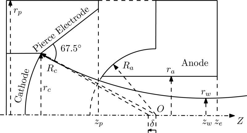
Figure 2 shows a generic Pierce electron gun model with the corresponding notation for each geometric feature. The anode and the cathode surfaces were originally embedded in two concentric spheres with the center at “O.” An offset “δ” along the gun axis of the corresponding center of the cathode is necessary in order to correct for spherical abberations.8 Note that the same reference does not provide specifics regarding the features of the interior of the anode geometry, i.e., the electron gun exit channel geometry is not specified. Hence, a simplified cylindrical geometry was implemented in both cases. The angle of 67.5° of the Pierce electrode is with respect to the normal to the uncorrected cathode edge.
Figure 2.
The electron gun geometry in cylindrical coordinates. Oz is the axis of symmetry. The curved line represents the beam envelope.
In Fig. 2, indices “a,” “c,” “p,” and “w” refer to the anode, cathode, Pierce electrode, and beam waist, respectively. Also, ze is the axial coordinate where the anode ends. The values of the physical parameters of both electron guns are provided in Table TABLE I.. ΔV=Va-Vc represents the electric potential difference between the cathode and anode, I is the primary beam current, P is the perveance, and J is the current density. All other quantities in Table TABLE I. are the geometric parameters from Fig. 2.
TABLE I.
Design and physical parameters of the Litton L-2087 and Varian VTC6364 electron guns from Ref. 8. The additional data section contains the range of values used for the geometrical parametric study.
| Variable | Litton L-2087 | Varian VTC6364 | |||||
|---|---|---|---|---|---|---|---|
| (Reference 8) Data | ΔV(KV) | 10.0 | 9.5 | ||||
| I(A) | 0.550 | 0.373 | |||||
| P(μP) | 0.550 | 0.404 | |||||
| J(A∕cm2) | 1.737 | 1.593 | |||||
| rw(mm) | 0.940 | 0.838 | |||||
| rc(mm) | 3.175 | 2.731 | |||||
| ra(mm) | 2.286 | 1.727 | |||||
| zw(mm) | 17.323 | 16.511 | |||||
| Rc(mm) | 10.617 | 12.421 | |||||
| Ra(mm) | 5.200 | 4.877 | |||||
| δ(mm) | −1.190 | 0.494 | |||||
| Range | Range | ||||||
| Additional data | rp(mm) | 9 | (8,10) | 9 | (8,10) | ||
| zp(mm) | 4.807 | (3.807, 5.807) | 4.427 | (3.427, 5,427) | |||
| ze(mm) | 21.807 | (20.807, 22.807) | 21.927 | (20.927, 22.927) | |||
In this study, the origin of the reference frame is in the central position of the cathode surface as used in Ref. 8. The value of the anode radius, Ra, is not provided in Ref. 8, but it can be derived from the formalism presented there. However, the accuracy of the formalism in Ref. 8 with respect to the real value of the anode radius is not known. In this study, the Ra values were chosen such that the electron guns perveance as computed at 3 kV, i.e., in the space charge limited regime, is as close as possible to the values reported in Ref. 8. The “additional data” is a minimal set of the unknown parameters required to completely define the electron gun models and perform the study. The values of these parameters were chosen such that the agreement between the model and experimental data is sufficient for the purposes of this study and at the same time the domain of integration of the problem remains small for computing efficiency. To determine the set of values for these parameters 125 model solutions for both guns were considered, corresponding to a cubic subdomain in the 3D parametric space generated by (rp, ze, and zp) with 2 mm side length and 0.5 mm distance between each representative point along the parametric space coordinate direction. This cube was centered in the values provided in Table TABLE I. for rp, ze, and zp. Note that large changes in rp, ze, and zp values produce only small changes in the value of the perveance, but small changes in the anode radius Ra have a dramatic impact on the perveance. Once all the geometrical parameters of the model were derived, emitted current was calculated as a function of applied voltages between 1 and 12 kV to determine the working point of the electron guns relative to the space charge limited region and the temperature dominated region.
The physics of the above Pierce guns was simulated in the presence of external magnetic fields by modeling the full three dimensional (3D) model using SCALA (Vector Fields Ltd. OPERA-3d) for 3D electromagnetic design analysis and simulation. The SCALA model includes the effect of the space charge interactions, which affect beams of charged particles and arbitrary three dimensional external magnetic fields can be applied. SCALA also includes the self-magnetic fields generated by the beam; however, the simulations showed a change in beam waist position and beam waist diameter below 1% and therefore this effect can be neglected. In addition, the simulation includes neither secondary electrons27 nor backscattered electrons, which may be caused by electron beam interaction with the anode surface. The SCALA program does not provide an integrated Monte Carlo simulator for these phenomena. It is expected that secondary electron production is very low, although from previous experience in x-ray tube design,28 up to ≈50% of the fraction of electrons hitting a surface may backscatter. The contribution of these backscattered electrons to the primary electron beam will depend on material properties, geometry, and the external magnetic field. The conclusions presented here apply to the primary beam only, but this phenomenon of backscatter should be considered as an important driver of electron gun design that aims to avoid all collisions between the electron beam and the anode.
The model of thermionic emission is important because it determines the initial dynamics of the electron beam and will influence all the properties of the emitted beam. The details regarding cathode construction and heating mechanism were not provided in Ref. 8. Therefore, we have solved at zero magnetic field both Litton and Varian models for three different thermionic models, i.e., Child’s law, Fry∕Langmuir law and constant current density law to investigate the differences. Child’s law29 assume zero initial velocity for the emitted electrons and it is defined by
| (2) |
where J is the electron current density, ɛ0 is vacuum permittivity, d=0.3 mm is the sampling distance considered in simulations, e0 and m0 are the elementary charge and the electron mass, respectively, and V is the potential difference between gun electrodes. Fry∕Langmuir law30, 31 uses a more realistic assumption by considering a Maxwell distribution for the initial electron velocities in a thermionic emitter. The same sampling distance d=0.3 mm was used for the Fry∕Langmuir law. For the constant current density law the values for J from Table TABLE I. were used. The initial electron energy for the constant current density law was considered the mean value of electron energy emitted by the Fry∕Langmuir cathode. The simulations were performed under the assumption that the electron emitter is a tungsten dispenser cathode,25 which consists of a porous tungsten matrix impregnated with barium oxide (BaO), calcium oxide (CaO), and alumina (Al203) compounds with a proper molar ratio. The work function for a tungsten dispenser cathode is reported32 to have an approximate value of 2.0 eV. Based on this it was determined that a cathode with temperature of 1252 and 1248 K for Litton and Varian, respectively, will emit the beam current values from Table TABLE I.. The above temperatures are within the reported32 operating temperature range of 1173—1473 K for tungsten dispenser cathodes. As will be discussed later big differences were not observed between the simulation outcomes from these three emission models. Child’s law was therefore used as the thermionic mechanism for electron generation for all the simulations. The electric current generated by electron flow in the beam was determined at a plane perpendicular to the gun axis, which was positioned at the corresponding beam waist position zw from Table TABLE I.. The beam current is obtained by recording the individual current contribution carried by any macroparticle, which crosses the perpendicular plane during the simulation. A macroparticle is defined as an assemblage of N physical particles of the same type, e.g., electrons, which is modeled as a single unit.
The mrT fringe field
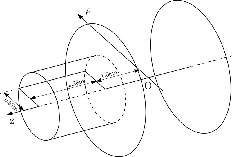
The gap between the mrT magnet poles is approximately 60 cm, which is big enough to accommodate an adult patient positioned perpendicular to its axis of symmetry, thus making the mrT magnet a good candidate for a proof of principle in-line MRI-linac system. The electron gun simulations for the in-line configuration between 0.02 and 0.16 T were performed using the fringe field of this magnet. For field values between 0 and 0.02 T for the in-line configuration and for the perpendicular case a constant magnetic field was implemented. The mrT system is not actively shielded and its magnetic field strength in the isocenter is rated at 0.5 T. The components of the magnetic field were measured in a cylinder along the axis of the magnet as shown in Fig. 3 to provide boundary conditions on the finite element model developed and solved with COMSOL Multiphysics.
Figure 3.
Sketch of the magnet and the region in space where the magnetic field was measured and interpolated. The big circles represent the magnet poles and the cylinder is the domain where the field was determined. The rectangle is the boundary along which the experimental measurements were performed.
The magnetic field has cylindrical symmetry, and so it is enough to know the magnetic field components at any point in a semiplane bounded by the axis of symmetry to completely specify the field everywhere in space. This reduces the 3D problem to an axially symmetric 2D problem, requiring measurement of the field in the 2D domain bounded by the rectangle in Fig. 3. The rectangle has a width of 0.57 m and a length of 2.28 m, and begins 1.08 m from the imaging isocenter of the magnet. The region is big enough to accommodate a straight through, i.e., no bending magnet, 6 MV linac like the Varian 600C for which a model has recently been designed.6 Maxwell’s equations then provide a unique solution of the field inside the domain.33 The magnetic field measurements were performed with a F. W. Bell model 5080 gaussmeter equipped with a transverse Hall sensor (model number STD58-0404). The analytic functions which interpolate the measurements of Hρ and Hz are
| (3a) |
| (3b) |
| (3c) |
with R-square values of 0.9937, 0.9961, and 0.9998 corresponding to Eqs. 3a, 3b, 3c, respectively. Because R-square values are close to 1, Eqs. 3a are successful in explaining the variation in the experimental data. The boundary conditions necessary to solve Maxwell’s equations are completely specified by the tangential components of the magnetic field with respect to the geometrical boundary which in this case correspond to Eq. 3a.
RESULTS AND DISCUSSION
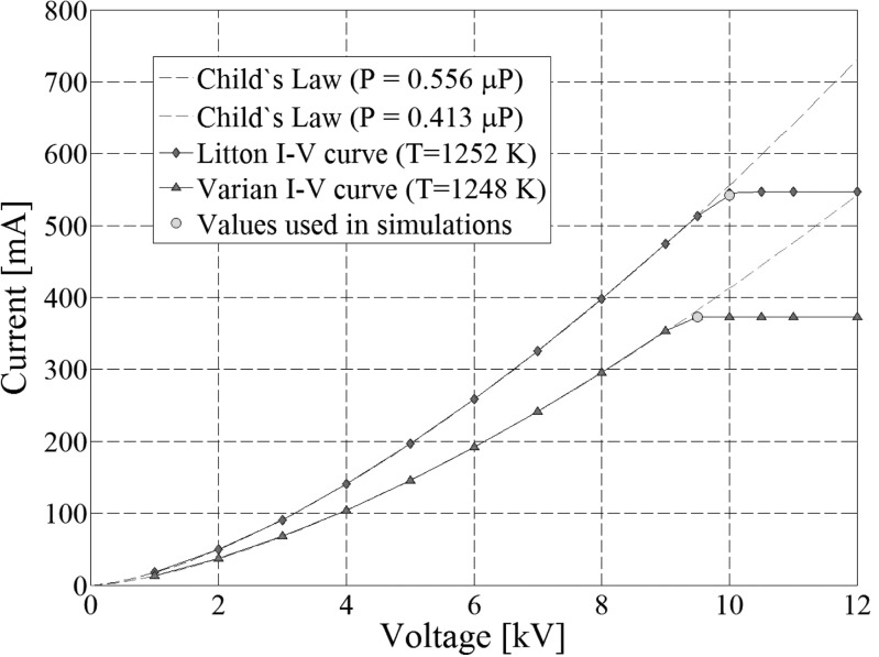
The first step in building the models was to choose an appropriate value for Ra such that the perveance of the electron guns is close to what is reported in Ref. 8. The differences between the anode radius values obtained using the formalism in Ref. 8 and the values reported in Table TABLE I. are -10.3 and 0.1% for Litton L-2087 and Varian VTC6364 electron guns, respectively. The simulations were performed at a potential difference of 3 kV for both guns to ensure that Child’s Law is valid. It was also determined that the change in perveance value of the gun as simulated at 3 kV is below 1% when the parameters rp, zp, and ze are changed. The potential difference from Table TABLE I. was next considered, and it was determined that the set of parameters in Table TABLE I. are optimal in the sense that the beam waist position does not change if the values of rp, zp, ze are increased but it decreases if their values are reduced. As can be seen in Fig. 4 the operating points of the guns are situated in the transition zone between the space-charged limited regime, where Child’s Law applies, and the temperature dominated region. Hence, the beam waist position was the only quantity used to choose an optimal set of additional parameters because the beam current did not change with rp, zp, and ze. The range of variation of these three parameters is roughly 10% of the model length and their impact on the change in beam waist position is below 1%, which made us conclude that rp, zp, and ze are not essential characteristics of the electron guns under study.
Figure 4.
Current-voltage characteristic curves for Litton and Varian electron guns. The dotted lines represent the Child’s law Eq. 2 corresponding to a perveance of 0.556 and 0.413 μP for Litton and Varian, respectively. The circles represent the working points of the guns as specified in Ref. 8, which are 2.34 and 2.36% off the 3∕2 power law curves for Litton and Varian, respectively. The emitted current at the working point is 0.543 and 0.373A for Litton and Varian, respectively.
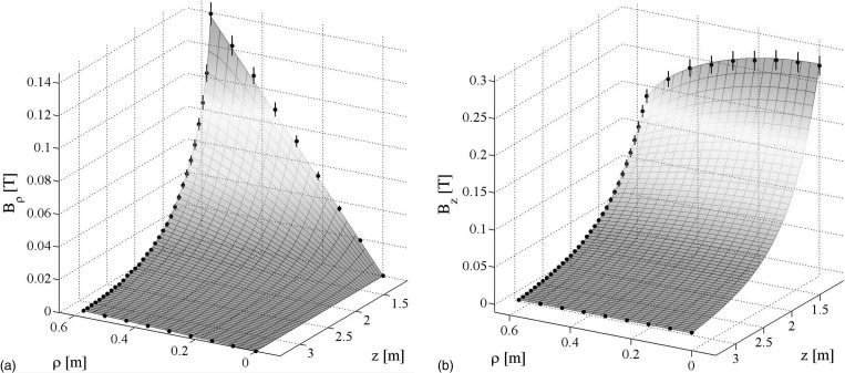
The solution from COMSOL Multiphysics, which is shown in Fig. 5, was used to generate a file which contains the magnetic field components at any node of the mesh associated with the SCALA finite element model. The 5% error bars in Fig. 5 are due to positional uncertainty in the experimental data. Depending on the size of the treatment head and the length of the linac waveguide, the electron gun could sit anywhere between 1.5 and 3 m away from the isocenter, which corresponds to a field strength of 0.127 and 0.019 T, respectively. Thus, COMSOL Multiphysics and matlab were used to specify the relative position of the electron gun with respect to the MRI scanner isocenter in a range, which corresponded to field strengths between 0.02 and 0.16 T and to extract the corresponding magnetic field configuration. The full 3D magnetic field information is reconstructed from the 2D solution by using the axial symmetry of the problem. For regions far away from the isocenter of the magnet, i.e., for fields smaller than 0.02 T, the simulations were performed by specifying a constant magnetic field. This is a good approximation of the mrT field because the radial component far from the isocenter of the magnet and close to the axis of symmetry is very small compared to the axial component as shown in Fig. 5.
Figure 5.
(a) The radial and (b) axial components of the fringe field of the mrT system obtained with COMSOL Multiphysics. The magnetic field measurements drawn as black dots along with the corresponding 5% error bars were used to specify the boundary conditions of the problem.
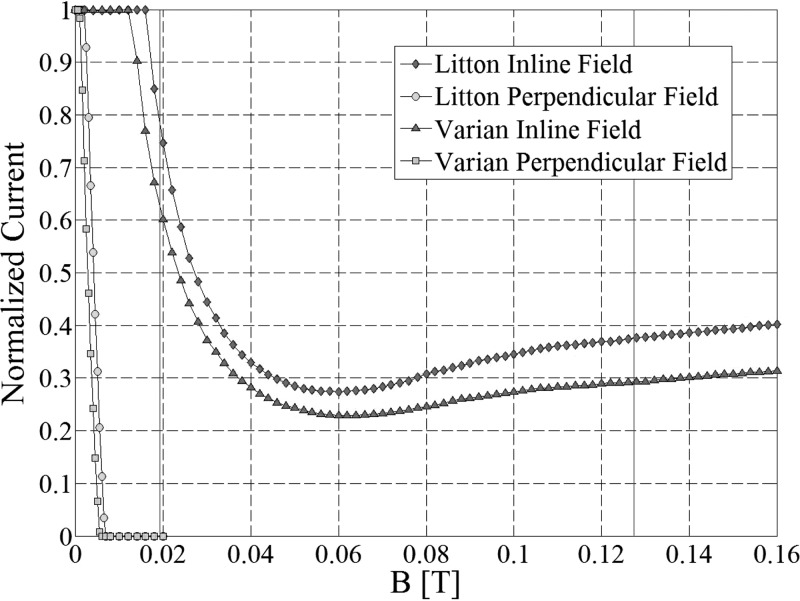
The dependence of the scaled electron beam current on the external magnetic field is given in Fig. 6 for both Litton L-2087 and Varian VTC6364 electron guns. The scaling constants used throughout the manuscript were the values of the electron beam current emitted at zero magnetic field, i.e., 0.543A and 0.373A for Litton L-2087 and Varian VTC6364 electron guns, respectively, which agree with the measured values of Ref. 8 to within 1.27%. In addition to the magnitude and orientation of the external magnetic field, the electron gun geometry is a major contributing factor to the final value of the primary beam current. This is clearly represented in Fig. 6 where different values of the primary beam current are obtained for the same value of the external magnetic field. Although the geometric dimensions of the two electron guns are different, their overall behavior is similar. In fact the results obtained here are consistent with results obtained independently by other groups4, 5 for different geometry Pierce guns and with a space charge limited cathode. This shows that any Pierce electron gun will have a qualitative behavior in magnetic fields similar to the ones presented in Fig. 6 regardless of the working regime, i.e., space charge limited or not. The findings regarding the current dependence on external fields can be extended to actively shielded MRI magnets. In this case the magnitude of the fringe field is smaller compared to the fringe field strength of the mrT magnet. However, the qualitative results will remain the same in the sense that the beam current value will have an initial constant plateau after which it will start to decrease as shown in Fig. 6.
Figure 6.
Dependence of the scaled electron beam current on the external magnetic field. The vertical solid lines delimit field values corresponding to distances between 1.5 and 3 m for the in-line configuration.
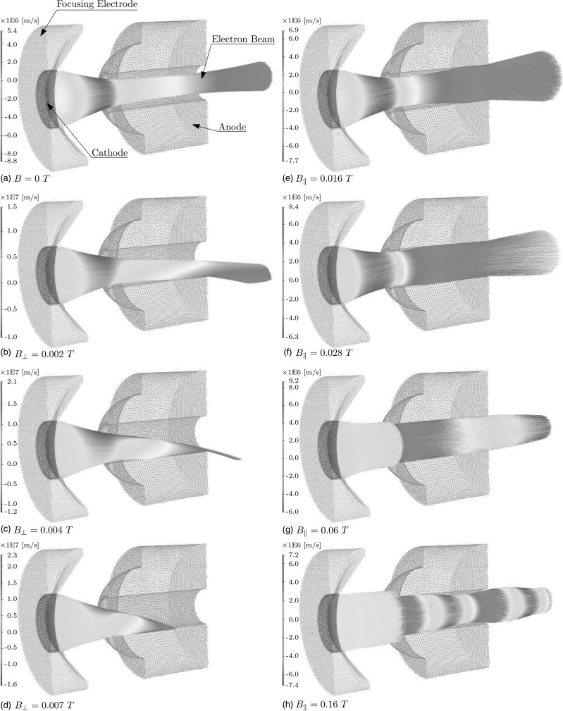
For the case when the magnetic field is perpendicular to the gun axis of symmetry, as the strength of the magnetic field increases the value of the current stays on an initial plateau, after which it starts to decrease until it vanishes at around 0.007 T for Litton L-2087 and 0.006 T for Varian VTC6364, respectively. Regarding the plateau, the current remains unchanged up to 0.002 T for Litton L-2087 and up to 0.0005 T for Varian VTC6364. However, even at small field strengths the electron beam is deflected from its original path and cannot be used in acceleration as it will hit the walls of the first few cavities of the waveguide.5 This situation is depicted in panel (b) in Fig. 7 where part of the Litton L-2087 beam hits the surface of the anode track because of the action of the perpendicular magnetic field. The bending of the beam increases with field strength, as shown in panel (c) of Fig. 7, until all of the current hits the anode surface as shown in panel (d).
Figure 7.
Litton L-2087 electron gun with computed electron trajectories: (a) without magnetic field, (b–d) for perpendicular magnetic fields corresponding to 100, 50, and 0%, respectively of the initial current (e–h) for in-line magnetic fields corresponding to 100%, 50%, minimum value, and 40.2%, respectively of the initial current. The corresponding value of the magnetic field is specified next to the picture labels. Color coding refers to the radial velocity of the electrons in the beam.
One way to correct beam deflection in perpendicular magnetic fields is to reduce the strength of the field in the electron gun region, thus decoupling the physics of the linac from that of the MRI scanner. There are several options available, including active shielding of the MRI magnet,34 building a passive or active magnetic shield around the linac,1, 16 or a combination of passive and active shielding methods. Note that the presence of shielding distorts the original field configuration, and one has to design the shield or even the magnet such that the magnetic field homogeneity in the field of view of the magnet is not degraded.35, 36
Passive shielding cannot be used as an efficient solution for arbitrarily high magnetic fields since even metals with high coercivity saturate. For example, MuMetal, which is a nickel–iron alloy and is a very common material used in passive shielding, saturates37 at 0.2 T despite its very high value of the relative permeability when no magnetic field is present. To obtain good shielding, one has to ensure that the field that needs to be shielded is much smaller than the saturation value of the shielding material. In addition, since the high-permeability alloys are magnetic, mechanical support sufficient to prevent displacement is also required.1, 2, 14, 15
For the in-line case, because the magnetic field is aligned with the gun axis, there is no global deflection away from the beam axis. However, the value of the primary beam current depends on the field strength for values of the field larger than 0.016 T for Litton L-2087 and 0.012 T for Varian VTC6364 due to collision of electrons in the beam with the anode walls. After the initial plateau, the current starts to decrease as the field strength increases, and it reaches a minimum of 27.5% at 0.06 T and 22.9% at 0.062 T for Litton L-2087 and Varian VTC6364, respectively. A slow increase of the primary beam current is observed after the minimum is reached. Thus at 0.16 T the beam current increases to 40.2 and 31.4% from the original value of the current for Litton L-2087 and Varian VTC6364, respectively.
Current is removed from the beam due to electron interactions with the surface of the entrance aperture of the anode and due to electron interaction with the inner surface of the anode cavity. To quantify these effects, Ie was set equal to the scaled current hitting the anode entrance, and Ii is the scaled current lost due to beam interaction with the anode cavity. If the scaled current value obtained from simulation is Im, then
| (4) |
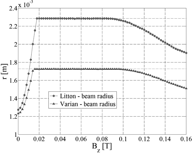
The dependence of the above currents on the external field is shown in Fig. 8 for the Litton L-2087 electron gun. The initial decrease of Im after the plateau is mainly due to the interactions of the beam with the inner surface of the anode cavity. The gradual increase of the number of interactions with the inner cavity is shown in panels (a), (e) and (f) in Fig. 7. At 0.042 T the field is strong enough to bend the electron trajectories and produce interactions with the entrance surface of the anode as seen in panels (g) and (h). At high values of the field strength the interactions with the inner walls of the anode decrease significantly. This is mainly due to the fact that the Larmor radius is inversely proportional to the external magnetic field, and at values higher than 0.1 T the Larmor radius is 1 order of magnitude smaller than the diameter of the anode cavity. As a result, a lot of particles which otherwise were lost in the interactions with the walls of the anode drift tube start to contribute to primary beam current. As the field increases, the Larmor radius decreases and therefore more particles will contribute to the final current value, which explains the slight increase in the current. This phenomenon is also reflected in the way the beam radius changes with the external field as shown in Fig. 9. In general, at field strengths above 0.1 T and inside the anode drift tube, the space charge interaction between beam particles is not exactly balanced by the action of the Lorentz force. This causes beam scalloping,38 i.e., the beam radius has a periodic variation, as shown in panel (h) of Fig. 7. When the beam radius is at its maximum the Lorentz force action dominates resulting in a focusing effect on the beam. Conversely, when the beam radius reaches its minimum the space charge interaction is dominant, so the beam starts to expand.
Figure 8.
Scaled anode currents for Litton L-2087.
Figure 9.
Beam radius dependence on the external field (in-line case) computed at beam waist position. All the particles in the beam were considered in the computation of the beam radius.
The rms beam emittance εrms is an important figure of merit based on the effective volume occupied by the beam distribution in phase space. A small value of the rms emittance would correspond to similar dynamic properties of the particles in the beam, which describes a quasilaminar flow. The rms emittance can be defined based on phase space information as39
| (5) |
is the angle in the XZ-plane a particle makes with the beam axis of symmetry, i.e., Z-axis, in the paraxial approximation. Also, one of the Courant–Snyder parameters, i.e., α, whose sign controls the beam convergence can be computed as39
| (6) |
α is positive for convergent flow, zero when there is no radial motion, and negative for divergent flow. Based on this, one can determine the position along the beam where, statistically speaking, the particles have zero radial velocity which is of interest when deciding the capture position of the beam by a radio frequency (RF) accelerating structure. The degree of convergence is given by the slope of the beam envelope which is defined as -α∕β. At zero external field the beam rms emittance is 1.54 and 1.32π-mm-mrad for Litton L-2087 and Varian VTC6364, respectively. Also, α vanishes at 15.587 and 15.187 mm for Litton L-2087 and Varian VTC6364, respectively. At zero magnetic field, α vanishes at beam waist position which accounts for a -10 and -8% difference from experimental data for the beam waist position for Litton L-2087 and Varian VTC6364, respectively. By geometrical arguments the beam waist radius can be computed as39
| (7) |
where β is one of the Courant–Snyder parameters defined as
| (8) |
At zero magnetic field, the beam radius is found to be 0.68 and 0.65 mm for Litton L-2087 and Varian VTC6364, respectively. This corresponds to a −27 and -22% difference from experimental data for the beam waist radius for Litton L-2087 and Varian VTC6364, respectively. Note that there is no common agreement in the research community on how the beam radius is defined for arbitrary beam distributions and Vaughan8 does not provide details about beam measurements. Also, the rms emittance takes into account only 39% of the central part of the beam. If all of the particles are included then the beam radius is 1.275 and 1.233 mm for Litton L-2087 and Varian VTC6364, respectively. This corresponds to a +36 and +47% difference from experimental data in the beam waist radius for Litton L-2087 and Varian VTC6364, respectively, an indication of the variability of the beam radius value depending on the definition used for computation. However, the fluctuations are around the experimentally measured value. The above derivations show that the SCALA models are reasonable representations of the real electron guns and that the simulation outcome is consistent with the experimental data reported by Vaughan.8
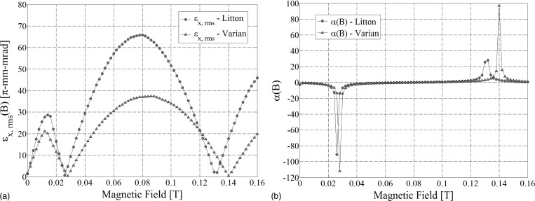
For in-line configuration, the dependence of εx,rms and α on the external magnetic field is shown in Fig. 10. The values of εx,rms and α were determined at the beam waist position zw. It is interesting to note that the rms emittance reaches a minimum when α is maximum in magnitude. Litton L-2087 rms emittance reaches a minimum of 0.72 and 2.01π-mm-mrad at 0.026 and 0.132 T, respectively. Varian VTC6364 rms emittance reaches a minimum of 0.34 and 0.35π-mm-mrad at 0.028 and 0.14 T, respectively.
Figure 10.
(a) Beam emittance and (b) Courrant–Snyder α parameter dependence on the value of the external magnetic field (in-line configuration) computed at beam waist position zw from Table TABLE I.. The minima of the emittance for nonzero values of the magnetic field also correspond for the most beam divergent and most beam convergent cases in the considered range. The most beam divergent cases have a beam slope of 49.93 and 48.03 for Litton and Varian, respectively, whereas the most beam convergent cases have a beam slope of −60.83 and −60.52 for Litton and Varian, respectively.
No large differences were seen between solutions coming from the three different idealized 1D thermionic models, i.e., Child’s law, Langmuir-Fry law or constant current density law. A change from Child’s law of less than 1% was observed for the beam waist position and less than 5% for the beam rms emittance. These findings are related to the fact that the geometries of the guns that were used in the simulations place the operating points of the guns close to the 3∕2 power law curves, in the transition zone between the space-charged limited regime and the temperature dominated region as can be seen in Fig. 4. Child’s Law still applies in that region to a certain degree of approximation, i.e., less than 2.5% off the 3∕2 power law, with some temperature dependence of the emitted current. In fact this is why the three emission models considered here, i.e., Child’s Law, Langmuir–Fry and constant current density model, provide similar results, further validating the use of Child’s Law. It is likely that the original Pierce electrode geometry, and also the anode geometry are more complicated than what was considered here and described in Ref. 8; more complex geometries would likely amplify the differences between solutions derived using different thermionic models. Therefore Child’s thermionic emission model was used for all the simulations.
The fundamental difference of the in-line case compared to the perpendicular case is the way the electron beam path deviates from the gun axis. For the in-line case it is not necessary to decouple the physics of the two subsystems, i.e., magnetically shield the gun, because there is no beam deflection. However, for nonvanishing axial fields the original beam characteristics are lost which clearly shows that a magnetically coupled solution is theoretically possible only with electron gun modifications. Assuming that the mrT magnet is used together with a reasonably short electron linac, then the electron beam will experience fields which are higher than 0.1 T. At this value of the magnetic field the electron beam is confined along its path as in panel H) of Fig. 7 and no magnetic lenses are needed for beam confinement along the waveguide.4 However, the electron gun will have to be redesigned so that electrons will not hit the anode while ensuring that the nominal beam parameters as described by the Courant-Snyder parameters are kept close to their original values in the absence of the external magnetic field.
CONCLUSIONS
In this work, the behavior of two electron guns in perpendicular and in-line magnetic fields was analyzed. It was found that even for different geometrical parameters the Pierce type electron guns will exhibit a qualitatively similar behavior for a given external magnetic field configuration. For the perpendicular case it is necessary to decouple the physics of the linac and MRI scanner in order to ensure a functioning electron gun. For the in-line case there is no global deflection away from the beam axis and the beam current does not vanish even at very high values of the magnetic fields. For the in-line configuration beam loss of up to 77.1% were observed as opposed to complete current loss for the perpendicular configuration. For in-line configuration it was determined that the rms beam emittance reaches two minima for relatively high values of the external magnetic field in the considered range of field strengths.
ACKNOWLEDGMENTS
The authors would like to thank Dr. Magdalena Constantin and Libby Roberts of Stanford University and Dr. Lois Holloway of Sydney University for reviewing the manuscript. Thanks to Dr. Kim Butts-Pauly, Dr. Steve Conolly, Dr. Norbert Pelc, Dr. Amit Sawant, Dr. Greig Scott, and Dr. Lei Xing of Stanford University for input into the original in-line MRI-linac concept. Many thanks to Prasheel Lillaney who helped with the measurements of the mrT magnetic field. This work was supported in part by NIH Grant No. T32-CA09695.
References
- Fallone B. G., Murray B., Rathee S., Stanescu T., Steciw S., Vidakovic S., Blosser E., and Tymofichuk D., “First MR images obtained during megavoltage photon irradiation from a prototype integrated linac-MR system,” Med. Phys. 36:2084–2088 (2009). 10.1118/1.3125662 [DOI] [PubMed] [Google Scholar]
- Raaymakers B. W., Lagendijk J. J. W., Overweg J., Kok J. G. M., Raaijmakers A. J. E., Kerkhof E. M., van der Put R. W., Meijsing I., Crijns S. P. M., Benedosso F., van Vulpen M., de Graaff C. H. W., Allen J., and Brown K. J., “Integrating a 1.5 T MRI scanner with a 6 MV accelerator: proof of concept,” Phys. Med. Biol. 54, N229–N237 (2009). 10.1088/0031-9155/54/12/N01 [DOI] [PubMed] [Google Scholar]
- Aubin J. St., Steciw S., Kirkby C., and Fallone B. G., “An integrated 6 MV linear accelerator model from electron gun to dose in a water tank,” Med. Phys. 37, 2279–2288 (2010). 10.1118/1.3397455 [DOI] [PubMed] [Google Scholar]
- Aubin J. St., Santos D. M., Steciw S., and Fallone B. G., “Effect of longitudinal magnetic fields on a simulated in-line 6 MV linac,” Med. Phys. 37, 4916–4923 (2010). 10.1118/1.3481513 [DOI] [PubMed] [Google Scholar]
- Aubin J. St., Steciw S., and Fallone B. G., “Effect of transverse magnetic fields on a simulated in-line 6 MV linac,” Phys. Med. Biol. 55, 4861–4769 (2010). 10.1088/0031-9155/55/16/015 [DOI] [PubMed] [Google Scholar]
- Aubin J. St., Steciw S., and Fallone B. G., “The design of a simulated in-line side-coupled 6 MV linear accelerator waveguide,” Med. Phys. 37, 466–476 (2010). 10.1118/1.3276778 [DOI] [PubMed] [Google Scholar]
- Kirkby C., Murray B., Rathee S., and Fallone B. G., “Lung dosimetry in a linac-MRI radiotherapy unit with a longitudinal magnetic field,” Med. Phys. 37, 4722–4732 (2010). 10.1118/1.3475942 [DOI] [PubMed] [Google Scholar]
- Vaughan J. R. M., “Synthesis of the pierce gun,” IEEE Trans. Electron Devices ED- 28, 37–41 (1981). 10.1109/T-ED.1981.20279 [DOI] [Google Scholar]
- Green M., “WE-D-BRC-02: Magnetic field effects on radiation dose distribution,” Med. Phys. 36, 2774 (2009). 10.1118/1.3182525 [DOI] [Google Scholar]
- Fallone B., “WE-D-BRC-03: Real-time MR-guided radiotherapy: Integration of a low-field MR system,” Med. Phys. 36, 2774 (2009). 10.1118/1.3182526 [DOI] [Google Scholar]
- Constantin D., Fahrig R., and Keall P., “TU-B-204B-02: A study of the effect of inline and perpendicular magnetic fields on beam characteristics of medical linear accelerator electron guns,” Med. Phys. 37, 3376 (2010). 10.1118/1.3469191 [DOI] [PMC free article] [PubMed] [Google Scholar]
- Lawson J. D., The Physics of Charged-Particle Beams (Clarendon, Oxford University Press, Oxford, England, 1988). [Google Scholar]
- Glass M. S., “Straight-field permanent magnets of minimum weight for TWT focusing-design and graphic aids in design,” Proc. IRE B 45, 1100–1105 (1957). 10.1109/JRPROC.1957.278267 [DOI] [Google Scholar]
- Fallone G., Carlone M., Murray B., Rathee S., and Steciw S., “Investigations in the design of a novel linac-MRI system,” Int. J. Radiat. Oncol. 69, S19 (2007). [Google Scholar]
- Lagendijk J. J. W., Raaymakers B. W., Raaijmakers A. J. E., Overweg J., Brown K. J., Kerkhof E. M., van der Put R. W., Hardemark B., van Vutpen M., and van der Heide U. A., “MRI/linac integration,” Radiother. Oncol. 86, 25–29 (2008). 10.1016/j.radonc.2007.10.034 [DOI] [PubMed] [Google Scholar]
- Aubin J. St., Steciw S., and Fallone B. G., “Magnetic decoupling of the linac in a low field biplanar linac-MR system,” Med. Phys. 37, 4755–4761 (2010). 10.1118/1.3480482 [DOI] [PubMed] [Google Scholar]
- Bielajew A. F., “The effect of strong longitudinal magnetic-fields on dose deposition from Electron and photon beams,” Med. Phys. 20, 1171–1179 (1993). 10.1118/1.597149 [DOI] [PubMed] [Google Scholar]
- Litzenberg D. W., Fraass B. A., McShan D. L., O’Donnell T. W., Roberts D. A., Becchetti F. D., Bielajew A. F., and Moran J. M., “An apparatus for applying strong longitudinal magnetic fields to clinical photon and electron beams,” Phys. Med. Biol. 46, N105–N115 (2001). 10.1088/0031-9155/46/5/401 [DOI] [PubMed] [Google Scholar]
- Raaijmakers A. J. E., Raaymakers B. W., and Lagendijk J. J. W., “Integrating a MRI Scanner with a 6 MV radiotherapy accelerator: Dose increase at tissue air interfaces in a lateral magnetic field due to returning electrons,” Phys. Med. Biol. 50, 1363–1376 (2005). 10.1088/0031-9155/50/7/002 [DOI] [PubMed] [Google Scholar]
- Kirkby C., Stanescu T., Rathee S., Carlone M., Murray B., and Fallone B. G., “Patient dosimetry for hybrid MRI-radiotherapy systems,” Med. Phys. 35, 1019–1027 (2008). 10.1118/1.2839104 [DOI] [PubMed] [Google Scholar]
- Fahrig R., Butts K., Rowlands J. A., Saunders R., Stanton J., Stevens G. M., Daniel B. L., Wen Z., Ergun D. L., and Pelc N. J., “A truly hybrid interventional MR/X-ray system: Feasibility demonstration,” J. Magn. Reson. Imaging 13, 294–300 (2001). [DOI] [PubMed] [Google Scholar]
- Friedrichs P. B. and Konrad G. T., “Focusing of a megavoltage electron beam in a medical accelerator,” Nucl. Instrum. Meth. Phys. Res. B 56, 1263–1265 (1991). 10.1016/0168-583X(91)95147-6 [DOI] [Google Scholar]
- Rinolfi L., “Computational tools for accelerator design,” in Cern Accelerator School Cyclotrons, Linacs and Their Applications (CERN 96-02) edited by Turner S. (Geneva, Switzerland, 1996), p. 363.
- Gonichon J. and Tronc D., “Acceleration and bunching in a 6 MV X band linac,” In EPAC96. Fifth European Particle Accelerator Conference, edited by Myers S., Pacheco A., Pascual R., Ch. Petit-Jean-Genaz , and Poole J. (Bristol, UK, 1997), Vol. 2, p. 1362.
- Karzmark C. J., Nunan C. S., and Tanabe E., Medical Electron Accelerators (McGraw-Hill, Inc., New York, 1993). [Google Scholar]
- Karzmark C. J. and Pering N. C., “Electron linear accelerators for radiation therapy: History, principles and contemporary developments,” Phys. Med. Biol. 18, 321–354, 1973. 10.1088/0031-9155/18/3/001 [DOI] [PubMed] [Google Scholar]
- McAllister L. E., “Secondary electron emission from copper and copper oxide surfaces,” Phys. Rev. 21, 122–130 (1922). 10.1103/PhysRev.21.122 [DOI] [Google Scholar]
- Wen Z., Pelc N. J., Nelson W. R., and Fahrig R., “Study of increased radiation when an x-ray tube is placed in a strong magnetic field,” Med. Phys. 34, 408–418 (2007). 10.1118/1.2404618 [DOI] [PubMed] [Google Scholar]
- Child C. D., “Discharge from hot CaO,” Phys. Rev. (Series I) 32, 492–511 (1911). [Google Scholar]
- Fry T. C., “The thermionic current between parallel plane electrodes; Velocities of emission distributed according to Maxwell’s law,” Phys. Rev. 17, 441–452 (1921). 10.1103/PhysRev.17.441 [DOI] [Google Scholar]
- Langmuir I., “The effect of space charge and initial velocities on the potential distribution and thermionic current between parallel plane electrodes,” Phys. Rev. 21, 419–435 (1923). 10.1103/PhysRev.21.419 [DOI] [Google Scholar]
- Thomas R.E., Gibson J. W., Haas G. A., and R. H.Abrams, Jr. “Thermionic sources for high-brightness electron beams,” IEEE Trans. Electron Devices, 37, 850–861, 1990. 10.1109/16.47802 [DOI] [Google Scholar]
- Jackson J. D., Classical Electrodynamics (John Wiley & Sons, Inc., New York, 1975). [Google Scholar]
- Raaymakers B. W., Raaijmakers A. J. E., Kotte A. N. T. J., Jette D., and Lagendijk J. J. W., “Integrating a MRI scanner with a 6 MV radiotherapy accelerator: Dose deposition in a transverse magnetic field,” Phys. Med. Biol. 49, 4109–4118 (2004). 10.1088/0031-9155/49/17/019 [DOI] [PubMed] [Google Scholar]
- Fallone B., Carlone M., Murray B., Rathee S., Stanescu T., Steciw S., Wachowicz K., and Kirkby C., “TU-C-M100F-01: Development of a linac-MRI system for real-time ART,” Med. Phys. 34, 2547 (2007). 10.1118/1.2761342 [DOI] [Google Scholar]
- Steciw S., Stanescu T., Carlone M., and Fallone B. G., “TH-C-M100J-01: Magnetic shielding of a coupled MRI-linac system,” Med. Phys. 34, 2623 (2007). 10.1118/1.2761649 [DOI] [Google Scholar]
- Sumner T. J., Pendlebury J. M., and Smith K. F., “Convectional magnetic shielding,” J. Phys. D: Appl. Phys. 20, 1095–1101 (1987). 10.1088/0022-3727/20/9/001 [DOI] [Google Scholar]
- Gilmour A. S., Principles of Traveling Wave Tubes (Artec House, Inc., Norwood, Massachusetts, 1994). [Google Scholar]
- Wiedemann H., Particle Accelerator Physics (Springer-Verlag, Berlin, 2007). [Google Scholar]


