

Abstract
We coated nanoparticles including iron oxide nanoparticles and quantum dots with phospholipid-PEG using the newly developed dual solvent exchange method and demonstrated that, compared with the conventional film hydration method, the coating efficiency and quality of coated nanoparticles can be significantly improved. A better control of surface coating density and the amount of reactive groups on nanoparticle surface is achieved, allowing conjugation of different moieties with desirable surface concentrations, thus facilitating biomedical applications of nanoparticles.
Keywords: nanoparticle, coating, phospholipid-PEG, solvent exchange
Nanoparticles such as gold nanoparticles, superparamagnetic iron oxide nanoparticles and quantum dots (QDs) have manifested a great potential for a broad range of biomedical applications including in vitro diagnostics,1 cell tracking,2 molecular imaging,3-5 and drug/gene delivery.6-8 These nanoparticles have a common core/coating structure, i.e., nanocrystals of metals, metal oxides or semiconductors encapsulated in a coating layer formed by natural macromolecules or synthetic polymers. Although the physical functionality of a nanoparticle is mainly attributable to its crystalline core, the coating plays an indispensible role in the biomedical applications. The coating layer must render nanoparticles water-dispersible, prevent aggregation, reduce non-specific adsorption in biological systems, and provide a platform for conjugation of targeting ligands or other functionalities. The size, charge, hydrophilicity and flexibility of the coating molecules are critical mediators for the in vitro and in vivo performance of nanoparticles.5, 9, 10 Furthermore, the density and class of reactive groups on the nanoparticle surface are not only important for conjugation chemistry but also regulate the interactions between nanoparticles and their targets.1, 11, 12
To date, many nanocrystals are initially prepared as a colloid stabilized by hydrophobic surfactants in nonpolar solvents. For example, iron oxide nanoparticles and quantum dots can be synthesized by thermal decomposition of precursor compounds in organic solvents.13-15 These methods facilitate size tuning and improve the size distribution of nanocrystals. However, as-synthesized nanoparticles will aggregate in aqueous buffers unless protected by hydrophilic molecules. Previous studies have shown that hydrophilic polymers with sulfhydryl or carboxyl groups can bind covalently to certain nanoparticles through surface ligand exchange.15-17 However, with only a few exceptions, grafting desirable molecules onto a hydrophobic and often chemically inert crystal surface presents a major challenge. Further, with most available techniques, it is difficult to precisely control the density of coating polymers and subsequently functional groups on the nanoparticle surface.
Amphiphilic surfactants can be adsorbed to the surface of hydrophobic nanoparticles with the hydrophilic portion of the surfactants exposed to the aqueous solution. The adsorption is driven by hydrophobic interactions between the amphiphilic surfactants and the nanoparticle surface. Amphiphilic polymers with a low critical micelle concentration (CMC), e.g., Poloxamer®, Poloxamine® and lipid-PEG copolymer, can form a stable coating layer around hydrophobic cores.9, 18, 19 Amphiphilic polymer coated carbon nanotubes, polystyrene beads, quantum dots, and superparamagnetic iron oxide nanoparticles have been used in in vitro and in vivo applications.9, 19-23 This coating can be generalized for many hydrophobic nanocrystals because it does not rely on the reactivity of the crystal surface.19 This method can also be used to produce multifunctional nanoparticles by adding functionalized polymers to the initial coating mixture, making it an attractive approach for coating nanocrystals with hydrophobic surfaces.24
Hydrophobic nanocrystals are usually encapsulated with amphiphilic polymers through a film hydration process, as outlined in Scheme 1.21, 22, 24, 25 In this method, amphiphilic polymers and nanocrystals are first distributed in a thin film, which is often performed by dispersing all components in chloroform and evaporating the solvent with a rotary evaporator, resulting in a film with uniformly distributed components (Scheme 1, ➀). The components can assemble into water-dispersible nanoparticles when the film is hydrated in an aqueous buffer (Scheme 1, ➁). This process usually requires energy input from intensive heating and sonication. The coating formation depends on the polymer concentration, ionic strength, pH value and temperature.26, 27 Despite its broad usage, the film hydration procedure is hindered by two competing processes: formation of empty micelles by the coating polymers alone and aggregation of nanocrystals. The aggregation of nanocrystals is nearly irreversible due to their high surface energy. To avoid aggregation, it is crucial to separate the individual nanocrystals with the coating polymers in the thin film. A common approach is to increase the ratio between the coating polymers and nanocrystals in the initial mixture. However, it is difficult to achieve a good separation of nanocrystals using the film hydration method, and the coated nanoparticles are often accompanied by a large amount of empty micelles and aggregated nanocrystals. In addition, certain functional groups, e.g., maleimide, can hydrolyze readily in aqueous buffers once heated, thus incompatible with the film hydration method.
Scheme 1. A schematic diagram of assembling water-dispersible nanoparticles with film hydration vs. solvent exchange method.

A. Amphiphilic copolymers and nanocrystals with hydrophobic surfactants are initially dispersed in chloroform. B. In the film hydration method ( ➀ & ➁ ), amphiphilic polymers and nanocrystals precipitate into a film after chloroform is evaporated. C. The film is hydrated in aqueous buffers to form water-dispersible nanoparticles. D. In the solvent exchange method ( ➂ & ➃ ), chloroform is gradually substituted by DMSO to induce the assembly of amphiphilic molecules on the nanoparticle surface. E. The surface coating is finalized after DMSO is replaced by water. The background colors orange, blue and green denote chloroform, water and DMSO, respectively.
It has been shown that introducing non-solvents to a nanoparticle colloid may change the nanoparticle surface properties and induce their assembly into an ordered structure.28 The presence of proper surfactants can maintain mono-dispersity of nanoparticles during solvent exchange.29 Here we describe a dual solvent exchange method for forming water-dispersible nanoparticles with a small amount of amphiphilic polymers. In this method, the abrupt phase transition (from a solid film to a solution) in film hydration is replaced with a mild solvent exchange procedure performed entirely in solution. The coating efficiency and quality are improved considerably through coating formation induced in a solvent system with ascending polarity. This method also provides a means to control the density of coating molecules and reactive groups on the nanoparticle surface. Specifically, DMSO, which is miscible with chloroform and water, is used to bridge the gap between the two solvents. The coating process includes two solvent exchange procedures (Scheme 1, ➂ & ➃). Initially, DMSO is slowly added to the chloroform solution containing both nanocrystals and amphiphilic polymers. Then chloroform is selectively evaporated under vacuum due to its lower boiling point. In the second step, DMSO is replaced by water through washes with water using centrifugal tubes. During the two procedures, the solvent system moves from chloroform to water with solvent polarity increasing gradually. We found that the assembly of water-dispersible nanoparticles was induced by DMSO and solidified in water (See results below).
Using the solvent exchange method, we successfully coated four different nanocrystals with DSPE-mPEG (1,2-Distearoyl-phosphatidylethanolamine-methyl-polyethyleneglycol) copolymers. As shown in Table 1, these four types of nanocrystals include two types of iron oxide nanocrystals (spherical-shaped nanocrystals with 6.5 nm and 17 nm in size, respectively) and two types of quantum dots (QDs) (QD Type 1, roughly triangle shaped with 8 nm in size, and QD Type 2, roughly rod-shaped with 6.1 nm in diameter and 13.1 nm in length) (Table 1 and Supporting Information, Figure S4). The organic surfactant on iron oxide nanocrystals is oleic acid/oleylamine, while that on QDs is trioctylphosphine oxide. PEG is a hydrophilic polymer widely used for synthesizing biocompatible liposomes and nanoparticles.21, 22, 30 DSPE-mPEG has a very low CMC (~ 5 μM) due to the combination of a hydrophilic PEG chain and extremely hydrophobic long chain fatty acids.9, 25 As shown in Figures 1a – 1d, the coating layer formed by DSPE-mPEG is visible in TEM images with negative staining, where a monolayer of coated nanoparticles were observed without large aggregates. The coating thickness is similar to those reported for nanoparticles coatings and empty micelles formed with the film hydration method.21, 22, 26 The coating layer is more pronounced around small nanocrystals (Figures 1a and 1c) and seems thinner and heterogeneous with large and irregular-shaped nanocrystals (Figures 1b and 1d). This is likely due to the projection of three-dimensional nanocrystals onto the surface of the negative stain. It is unclear whether the surface density of the coating polymer decreased with large curvature (e.g., at corners). The coated iron oxide nanoparticles showed remarkable stability (Supporting Information, S1). There was no significantly change in the absorbance and emission spectra of QDs after coating with DSPE-mPEG (Supporting Information, S2).
Table 1.
Physical and chemical properties of nanocrystals for coating studies
| Material | Shape | Size | Surfactant |
|---|---|---|---|
| Iron oxide | Spherical | 6.5 nm | Oleic acid/ oleylamine |
| Iron oxide | Spherical | 17 nm | Oleic acid/ oleylamine |
| CdSe/ZnS | Triangular | ~ 8 nm | Trioctylphosphine oxide |
| CdSe/ZnS | Rod-like | ~6.1 × 13.1 nm | Trioctylphosphine oxide |
Figure 1. TEM images of DSPE-mPEG coated nanoparticles.
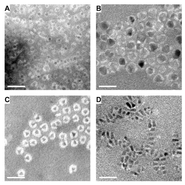
A. 6.5 nm iron oxide nanoparticles. B. 17 nm iron oxide nanoparticles. C. Triangle-shaped CdSe/ZnS quantum dots of 2~3 nm in size. D. Rod-like CdSe/ZnS quantum dots with length of ~10-15 nm. Scale bar = 40 nm.
The formation of micellar nanoparticles with 6.5 nm iron oxide nanocrystals and DSPE-mPEG is illustrated in Figure 2. The solution of nanocrystals remained optically clear after addition of DSPE-mPEG chloroform solution and DMSO (Figure 2A, 2), after removal of toluene and chloroform (Figure 2A, 3), and after substitution of DMSO with water (Figure 2A, 4). In contrast, when DMSO was added to the solution containing iron oxide nanocrystals in the absence of DSPE-mPEG, the nanocrystals formed aggregates (Figure 2A, 5). Dynamic light scattering (DLS) measurements indicated that the nanocrystals were well dispersed in toluene with an average hydrodynamic diameter of 8.12 nm (Figure 2B). Coated nanocrystals in DMSO exhibited a major peak at 34.6 nm. After transferred to water and purified by ultracentrifugation, the DSPE-mPEG coated iron oxide nanoparticles (IONPs) had an average hydrodynamic diameter of 27.8 nm. These results suggest that the iron oxide nanocrystals were stabilized by DSPE-mPEG in DMSO and formed uniformly distributed nanoparticles. The coated iron oxide nanoparticles are slightly larger in DMSO than in water. This is presumably due to increased solubility of DSPE-mPEG in DMSO, which may lead to a more extended conformation of coating molecules.
Figure 2. Iron oxide nanocrystals and coated nanoparticles at each solvent exchange stage.

A. 1. Iron oxide nanocrystals are dispersed in toluene. 2. DSPE-mPEG chloroform solution and DMSO are added to the solution. 3. Chloroform and toluene are removed. Iron oxide nanocrystals and DSPE-mPEG are in pure DMSO. 4. Iron oxide nanoparticles are transferred to water. 5. DMSO is added to the iron oxide nanocrystal solution in the absence of DSPE-mPEG. All solutions are diluted to contain 200 μg Fe/ml of iron oxide nanocrystals. B. Hydrodynamic sizes of iron oxide nanocrystals and coated nanoparticles measured by dynamic light scattering. Different curves are: Red, uncoated nanocrystals in toluene; Blue, coated nanocrystals in DMSO; Green, coated nanocrystals in water. The average size of uncoated nanocrystals in toluene (red curve), coated nanocrystals in DMSO (blue curve) and in water (green curve) are 8.12 nm, 34.6 nm and 27.8 nm respectively.
To elucidate the kinetics of coating formation, we examined the amount of water-dispersible nanoparticles, aggregates and empty micelles in solutions containing 6.5 nm iron oxide nanocrystals using several quantitative assays (Supporting Information, S4). The nanocrystals were coated with DSPE-mPEG at loading ratios (weight/weight ratio of DSPE-mPEG vs. iron) varying from 1:1 to 32:1. With both the solvent exchange method and the film hydration method, the same coating materials and iron oxide cores were transferred from 1 ml of toluene and chloroform mixture to 20 ml of deionized water. While the film hydration method can be improved by using a buffer with different compositions or volumes, this side-by-side comparison may help understand the difference between the dynamics of the two coating processes.
The aggregation of nanocrystals was evaluated by stabilized fraction, defined as the percentage of nanocrystals that could pass through a 0.2 μm syringe filter after the coating procedures. With the film hydration method, at 1:1 loading ratio, most nanocrystals formed large aggregates upon hydration and the stabilized fraction is merely 16% (Figure 3A). The stabilized fraction improved gradually and became 93% when the loading ratio increased from 1:1 to 32:1. In contrast, with the solvent exchange method, the stabilized fraction was nearly 100% in the entire range of loading ratio (Fig. 3A).
Figure 3. Dispersion efficiency and DSPE-mPEG density of DSPE-mPEG coated iron oxide nanoparticles.

6.5 nm iron oxide cores are coated with DSPE-mPEG with the loading ratio of DSPE-mPEG vs. iron ranging from 1:1 to 32:1. A. The dispersion efficiency of solvent exchange and film hydration methods. B. The average number of DSPE-mPEG per IONP.
We found that boiling DSPE-mPEG with perchloric acid could release its phosphate group, which could be quantified with Malachite Green assay.31 The surface density of DSPE-mPEG on the purified iron oxide nanocrystals could thus be estimated by measuring the molar ratio between DSPE-mPEG and iron oxide nanocrystals. With the solvent exchange method, the DSPE-mPEG density increased with the loading ratio and reached a plateau at 8:1 (Figure 3B). On average, there are 108 and 390 DSPE-mPEG molecules per IONP respectively at 1:1 and 32:1 loading ratios. With the same PEG length (2000 Da), it has been reported that at 25°C there are 76 DSPE-mPEG molecules in an empty micelle which has a hydrodynamic diameter of ~12 nm.21 On the other hand, the density of phospholipid on the cell plasma membrane (lipid bilayer) is approximately 5×10⁶ lipid molecules per μm2, which is equivalent to 567 phospholipid molecules in a lipid monolayer covering the surface of an IONP with 6.5 nm core and an oleic acid/oleylamine layer of ~1 nm in thickness.22 Therefore, the number of DSPE-mPEG per IONP shown in Fig. 3B falls within the lower bound (empty micelle) and upper bound (lipid bilayer of cell membrane). Interestingly, the PEG density in the coating generated by film hydration method is consistently lower and insensitive to the loading ratio compared with that of the solvent exchange method.
To further examine the coated nanoparticles, aggregates and empty micelles, we first estimated the molar concentration of iron oxide nanoparticles (Supporting Information, S4). The amount of aggregates and empty micelles were estimated based on the results presented in Figures 3A and 3B. Specifically, the amount of aggregates equals to the total iron content used in coating minus the stabilized fraction. Assuming that the DSPE-PEG molecules coated on large aggregates can be neglected (since the surface to volume ratio of large aggregates is small compared with the mono-dispersed nanoparticles), the amount of DSPE-PEG molecules on coated and mono-dispersed iron oxide nanoparticles was calculated as the number of iron oxide nanoparticles multiplied by average number of DSPE-PEG per nanoparticle. The amount of DSPE-PEG available for empty micelle formation was then determined as the total DSPE-PEG molecules used in coating minus the amount of DSPE-PEG coated on iron oxide nanoparticles.
We estimated that, at 1:1 loading ratio, with the film hydration method, the DSPE-mPEG available for empty micelle formation was 84.6% of the initial loading, whereas with solvent exchange method it was only 8.2%. The PEG density measurements were confirmed with the T2 measurements of IONPs. Only the T2 relaxivity of IONPs formed with solvent exchange method correlates well with the loading ratio (Supporting information, S3). Note that the results shown in Figure 3B were obtained after large aggregates and empty micelles were removed by centrifugation and filtering, in order to characterize the well-dispersed nanoparticles coated with respectively the film hydration and dual solvent exchange methods. In solvent exchange method the loss of nanoparticle samples due to filtration is negligible. However, when film hydration method was used, the loss of nanoparticle sample during filtration is significant, as shown in Figure 3A. Taken this into consideration, with film hydration method the average surface density of DSPE-PEG per nanoparticle may even be lower than that shown in Figure 3B.
The solvent exchange method can be used to coat iron oxide nanocrystals with many other phospholipid-PEG molecules, including combinations of phospholipids with 14 to 18 carbons and PEG molecules ranging from 1000 Da to 5000 Da (data not shown). However, when the PEG molecular weights are less than 750 Da, addition of DMSO induces nanocrystal aggregation and bubble formation in the solution. Phospholipid-PEG molecules with a small PEG size tend to form lamellar structure, since diminished PEG size allows formation of lipid bilayer.26 This suggests that the formation of coating on nanoparticles during solvent exchange may be in part attributable to the micellization of DSPE-PEG. It should be noted that the surfaces of all four nanocrystals selected for coating in this study were covered by a dense layer of alkyl chains of oleic acid, oleylamine and TOPO. We found that the absorption of phospholipid onto such a surface is more favorable than other hydrophobic surfaces (data not shown). The same coating approach may be extended to amphiphilic polymers with different composition and compatible solvent systems. The adsorption process depends on the interplay between nanoparticle surface and amphiphilic polymers in selected solvent system. The general conditions for solvent selection are: (1) the solvents should be compatible with the nanocrystals and the functional groups; (2) the intermediate solvent is miscible with the nonpolar solvent and water; and (3) the intermediate solvent should have a high boiling temperature so that it can be retained during selective evaporation. Therefore, the solvents used in the solvent exchange method are not limited to chloroform and DMSO; they may include DMF and certain members of alcohol family.
DSPE-mPEG coated nanoparticles are typically functionalized by using a mixture of DSPE-mPEG (no functional group) and DSPE-PEG (with functional end groups) for coating, in order to conjugate specific moieties for biomedical applications. However, little is known about how end groups with different sizes and charges affect coating formation. We coated 6.5 nm iron oxide nanocrystals with a mixture of DSPE-PEG-NH2 and DSPE-mPEG using the solvent exchange method. The percentage of DSPE-PEG-NH2 varied in the mixture, while the loading ratio between the total DSPE-PEGs and iron was fixed at 2:1. We found that the number of DSPE-PEG-NH2 per IONP was linearly proportional to its molar loading ratio as measured with fluorescamine method (Figure 4A). The IONPs with DSPE-PEG-NH2 alone have 150 amine groups per particle, similar to that of the DSPE-mPEG density determined previously. To examine the distribution of amine groups among IONPs after dual solvent exchange, amine functionalized IONPs without purification were examined with gel electrophoresis.32 The electrophoretic mobility of IONPs is determined by their size and zeta potential. For an amine functionalized IONP, the zeta potential depends mainly on positively charged amine groups on the particle surface and to a less extent on negatively charged phosphate groups buried in the PEG layer. After gel electrophoresis, IONPs were separated into a clear ladder pattern (Figure 4B). The non-functionalized IONPs moved toward cathode and the ones with amine groups shifted toward anode. We found that the distances between the bands are consistent with the differences in the loading ratio of DSPE-PEG-NH2 (Fig. 4B), and the amine groups are uniformly distributed among the IONPs within each group as indicated by the narrow bands, as shown in Fig. 4B.
Figure 4. Functionalization of DSPE-PEG coated iron oxide nanoparticles in solvent exchange method.

6.5 nm iron oxide nanocrystals were coated with a mixture of DSPE-mPEG and DSPE-PEG-NH2. A. The number of DSPE-PEG-NH2 on each IONP vs. the molar ratio of DSPE-PEG-NH2 in the coating mixture. B. The bright field image of IONPs separated by gel electrophoresis. The lanes from top to bottom are the IONPs coated with 100%, 80%, 60%, 40%, 20%, 10% and 0% DSPE-PEG-NH2. The “+” and “−” indicate cathode and anode in gel electrophoresis respectively.
The ability to control the number of functional groups per IONP is critical in preparing nanoparticles for specific biomedical applications. To examine this ability, we coated nanoparticles with negatively charged DSPE-PEG-COOH, which are additive to phosphates and thus can be better discerned in gel electrophoresis. We found that, with the solvent exchange method, IONPs with 1% increment in the DSPE-PEG-COOH loading ratio could be distinguished after gel electrophoresis even without nanoparticle purification (Figure 5A, lanes 1 through 4 in the left panel). In contrast, the film hydration method could not yield uniformly functionalized IONPs (Figure 5A, lane 5). Likewise, the number of COOH groups could be well controlled for coated quantum dots with the solvent exchange method (Figure 5A, right panel). The difference in the migration distance of QDs in gel electrophoresis was not as significant as that of IONPs. This discrepancy might be due to the changes in the relative contribution of phosphates and COOH groups to zeta potential when the particle shape changes.
Figure 5. Fine tuning functional groups on DSPE-PEG coated nanoparticles.
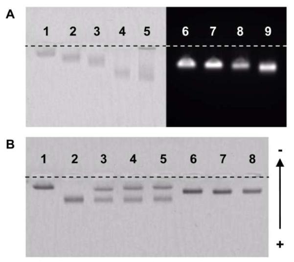
A. The gel image of IONPs and quantum dots coated with different ratios of DSPE-PEG-COOH. In A, the left panel is the bright field image of the IONPs. Lanes 1 through 4 are IONPs coated with 0%, 1%, 2% and 5% DSPE-PEG-COOH. Lane 5 shows IONPs coated with 5% DSPE-PEG-COOH using the film hydration method. The right panel is the fluorescence image of the quantum dots. Lanes 6 through 9 are quantum dots with 0%, 1%, 2% and 5% DSPE-PEG-COOH. B. The bright field image of IONPs. Lanes 1 and 2 are IONPs with 1% and 10% DSPE-PEG-COOH. Lanes 3, 4, 5 are IONP samples used in lanes 1 and 2 mixed in water for 1, 2 and 24 hours, respectively. Lanes 6, 7, 8 are IONP samples used in lanes 1 and 2 mixed in DMSO for 1, 2 and 24 hours. All IONPs were used without purification after coating.
Previous studies have indicated that the amphiphilic polymers in micelles are in dynamic equilibrium with the monomeric polymers in solution.33 The exchange rate between the micellar and monomeric polymers is inversely related to its CMC or solubility in the solvent. To gain insight into the dynamic state of DSPE-PEG coated nanoparticles, we prepared two IONPs with 1% or 10% of DSPE-PEG-COOH in the coating using the solvent exchange method. After gel electrophoresis, the IONPs with 1% and 10% COOH group moved different distances (Figure 5B, Lanes 1 and 2). We also mixed the two samples at 1:1 ratio at the DMSO stage (Figure 2A, 3) or at the water stage (Figure 2A, 4) before performing gel electrophoresis. Samples mixed in water for 1, 2 and 24 hours all separated into two bands at the positions identical to the IONPs with 1% and 10% COOH group, respectively (Figure 5B, Lanes 3, 4 and 5). However, the two samples mixed in DMSO all merged into one band located at the middle position (Figure 5B, Lanes 6, 7 and 8). This clearly indicates that there was rapid exchange of DSPE-PEG in DMSO, whereas the exchange of DSPE-PEG in water was negligible, suggesting that IONPs in water are very stable.
Our results in Figure 3 confirm that film hydration method is prone to the aggregation of nanocrystals and the formation of empty micelles. Given that aggregated nanocrystals are very difficult to be separated, the film hydration coating process is a one-step irreversible reaction that relies on the distribution of nanocrystals in the film. While this can be improved by increasing the ratio between the coating molecules and the nanocrystals, it is difficult to achieve uniform distribution of nanocrystals in a thin film at nanometer scales. In addition, only the coating molecules near a nanocrystal are available for nanoparticle formation, while the coating molecules away from the nanocrystals will form empty micelles. As a result, with the film hydration method, a higher loading ratio leads to a larger stabilization fraction but has little effect on the surface density of coating molecules, as shown in Figures 3A and 3B.
The solvent exchange method benefits from the solution phase transition in DMSO. Uncoated nanocrystals distribute more uniformly and have a larger inter-particle distance in the colloidal solution than in a thin film. The solubility of DSPE-PEG is higher in DMSO than in water, which leads to a significantly suppressed micellization of DSPE-PEG alone while enables the formation of DSPE-PEG coated nanoparticles due to its higher polarity. It is conceivable that the interactions among uncoated nanocrystals and DSPE-PEG are diffusion-limited. Therefore, adsorption of DSPE-PEG onto the nanocrystal surface is a faster and dominant process compared with aggregation of nanocrystals in the solution. DMSO also enables rapid exchange between the DSPE-PEG on the particle surface and the monomeric DSPE-PEG; thus, the distribution of DSPE-PEG quickly approaches equilibrium after incubation. The equilibrium is evident in two aspects. First, the surface density of DSPE-PEG on coated nanoparticles increases with the loading ratio of DSPE-PEG, i.e., the concentration of DSPE-PEG in DMSO (Figure 3B). Secondly, DSPE-PEG with functional groups can always reach a highly uniform distribution among all coated nanoparticles (Figure 5B). After transferred into water, the preferred states of the nanoparticles are locked.
To examine the effectiveness of functionalized IONPs in biological studies, we coated 17 nm iron oxide nanocrystals with a mixture of DSPE-mPEG and DSPE-PEG maleimide (2:1 total loading ratio, 2% DSPE-PEG-maleimide) using the solvent exchange method. The 17 nm IONPs were further conjugated with anti-mouse IgG antibodies through thiol-maleimide reaction. The antibody-conjugated 17 nm IONPs were diluted with phosphate buffered saline containing 1% bovine serum albumin (BSA) and added to an ELISA plate coated with two proteins, mouse IgG and BSA (Figure 6A, inset). After one hour incubation at 37°C, it was found that the number of IONPs bound to the plate surface was linearly proportional to the concentration of mouse IgG loaded to the ELISA plate over a wide range of IgG concentration (Figure 6A); the non-specific binding between the IONPs and BSA was negligible (data not shown). When the amount of mouse IgG was kept constant and the concentration of loaded IONPs varied, we found that the amount of bound IONPs reached half of the saturation level at ~ 2 nM IONP loading concentration (Figure 6B). Since the binding affinity of antibodies is typically in the nano-molar range, this result indicates that, with 2% DSPE-PEG-maleimide in the coating, there were sufficient maleimide groups available on the surface of IONPs for antibody conjugation.
Figure 6. In vitro targeting with DSPE-PEG coated iron oxide nanoparticles.

Mouse IgG coated on a 96-well ELISA plate was detected with the 17 nm IONPs functionalized with 2% DSPE-PEG-maleimide and conjugated with horse anti-mouse IgG antibody. A. Surface bound IONPs as a function of mouse IgG density. The concentration of IONPs loaded to each well was kept constant. Inset in A is the schematic diagram of plate study. The green spheres represent mouse IgG. The brown ovals are BSA. B. Surface bound IONPs as a function of IONP loading concentration. The wells were coated with equal concentration of mouse IgG.
To demonstrate the potential biomedical applications of targeted nanoparticles, we functionalized IONPs to target folate receptor, which is a well established biomarker for cancer. Nanoparticles targeting folate receptor have broad applications in diagnosis and treatment of solid tumors.34, 35 To assess the capability of DSPE-PEG coated nanoparticles in cancer detection, 17 nm IONPs were conjugated with a goat anti-human folate receptor-1 antibody and labeled with a fluorescence molecule, DiI. Two cancer cell lines, HeLa (with high folate receptor expression) and MDA-MB-435s (with low folate receptor expression), were incubated with cell culture media containing the antibody conjugated IONPs. After incubation, the IONPs bound to HeLa cells but the binding to MDA-MB-435s cells was negligible (Figures 7A and 7B). This is consistent with the expression levels of folate receptor of the two cell lines (Figure 7C). The binding of the IONPs conjugated with a non-targeting control IgG was negligible with both cell lines (Figure 7D). Taken together, we found that antibody conjugated IONPs are highly specific and sensitive in detecting proteins bound to plate surface or expressed on the plasma membrane of cancer cell lines.
Figure 7. Cellular targeting of human folate receptor with DSPE-PEG coated iron oxide nanoparticles.
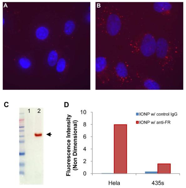
Human folate receptors on two cancer cell lines, MDA-MB-435s and HeLa, were detected with 17 nm IONPs. The IONPs were conjugated with goat anti-human folate receptor-1 antibody and labeled with a fluorescence molecule, DiI (ex/em = 549/580 nm). A and B are fluorescence images of MDA-MB-435s and HeLa cells, respectively. Cell nuclei were counterstained with Hoechst 33342. C. Western blots of human folate receptor (arrow). Lanes 1 and 2 are MDA-MB-435s and HeLa cells respectively. D. Flowcytometry analysis of the two cell lines treated with IONPs conjugated with the anti-folate receptor antibody or a non-targeting control IgG. All IONPs were labeled with DiI.
In summary, we have developed a novel dual solvent exchange method for coating nanoparticles by solvent transition from chloroform to a more polar DMSO and then to water, facilitating the self-assembly of polymer coating on nanoparticles. Compared with the conventional film hydration method, this new method is more efficient, requires less purification, and can be readily adopted for large-scale coating of a broad range of nanocrystals. In particular, the amount of initial amphiphilic polymer required for effective nanoparticle coating is one to two orders of magnitude lower than those reported in the literature, which minimizes the formation of empty micelles. We chose DSPE-PEG molecules for coating in this study since DSPE-PEGs with a variety of functional groups are commercially available. More importantly, the dual solvent exchange method facilitates a uniform and controllable surface modification of nanoparticles with variable surface density of DSPE-PEG and functional groups, which may reduce non specific interaction with proteins, achieve desirable in vivo biodistribution of nanoparticles, and significantly enhance the ability of nanoparticles to target specific disease markers. Therefore, the dual solvent exchange method we developed for self-assembly of amphiphilic polymer coating on nanoparticles may have significant implications for the biomedical application of nanoparticles in molecular imaging and targeted drug/gene delivery.
Supplementary Material
Acknowledgements
This work was supported by the National Heart Lung and Blood Institute of the NIH as a Program of Excellence in Nanotechnology Award (HHSN268201000043C to GB), and by an NIH Nanomedicine Development Center Award (PN2 EY018244 to GB).
Footnotes
Supporting Information Available: Supporting materials includes stability analysis, absorbance and emission spectra of quantum dots, T2 measurements of DSPE-mPEG coated 6.5 nm iron oxide nanocrystals and a complete description of the materials and methods used in experimentation. This material is available free of charge via the Internet at http://pubs.acs.org. This material is available free of charge via the Internet at http://pubs.acs.org.
References
- 1.Josephson L, Perez JM, Weissleder R. Angewandte Chemie-International Edition. 2001;40(17):3204–3206. doi: 10.1002/1521-3773(20010903)40:17<3204::AID-ANIE3204>3.0.CO;2-H. [DOI] [PubMed] [Google Scholar]
- 2.Lewin M, Carlesso N, Tung CH, Tang XW, Cory D, Scadden DT, Weissleder R. Nat Biotechnol. 2000;18(4):410–414. doi: 10.1038/74464. [DOI] [PubMed] [Google Scholar]
- 3.Nahrendorf M, Jaffer FA, Kelly KA, Sosnovik DE, Aikawa E, Libby P, Weissleder R. Circulation. 2006;114(14):1504–1511. doi: 10.1161/CIRCULATIONAHA.106.646380. [DOI] [PubMed] [Google Scholar]
- 4.Gao X, Cui Y, Levenson RM, Chung LW, Nie S. Nat Biotechnol. 2004;22(8):969–976. doi: 10.1038/nbt994. [DOI] [PubMed] [Google Scholar]
- 5.Tong S, Hou SJ, Zheng ZL, Zhou J, Bao G. Nano Letters. 2010;10(11):4607–4613. doi: 10.1021/nl102623x. [DOI] [PMC free article] [PubMed] [Google Scholar]
- 6.Alexiou C, Arnold W, Klein RJ, Parak FG, Hulin P, Bergemann C, Erhardt W, Wagenpfeil S, Lubbe AS. Cancer Res. 2000;60(23):6641–6648. [PubMed] [Google Scholar]
- 7.Namiki Y, Namiki T, Yoshida H, Ishii Y, Tsubota A, Koido S, Nariai K, Mitsunaga M, Yanagisawa S, Kashiwagi H, Mabashi Y, Yumoto Y, Hoshina S, Fujise K, Tada N. Nat Nanotechnol. 2009;4(9):598–606. doi: 10.1038/nnano.2009.202. [DOI] [PubMed] [Google Scholar]
- 8.Yezhelyev MV, Qi L, O’Regan RM, Nie S, Gao X. J Am Chem Soc. 2008;130(28):9006–9012. doi: 10.1021/ja800086u. [DOI] [PMC free article] [PubMed] [Google Scholar]
- 9.Torchilin VP, Trubetskoy VS. Advanced Drug Delivery Reviews. 1995;16(2-3):141–155. [Google Scholar]
- 10.Tromsdorf UI, Bigall NC, Kaul MG, Bruns OT, Nikolic MS, Mollwitz B, Sperling RA, Reimer R, Hohenberg H, Parak WJ, Forster S, Beisiegel U, Adam G, Weller H. Nano Letters. 2007;7(8):2422–2427. doi: 10.1021/nl071099b. [DOI] [PubMed] [Google Scholar]
- 11.Hazarika P, Ceyhan B, Niemeyer CM. Angewandte Chemie-International Edition. 2004;43(47):6469–6471. doi: 10.1002/anie.200461887. [DOI] [PubMed] [Google Scholar]
- 12.Montet X, Funovics M, Montet-Abou K, Weissleder R, Josephson L. J Med Chem. 2006;49(20):6087–6093. doi: 10.1021/jm060515m. [DOI] [PubMed] [Google Scholar]
- 13.Xie J, Peng S, Brower N, Pourmand N, Wang SX, Sun SH. Pure and Applied Chemistry. 2006;78(5):1003–1014. [Google Scholar]
- 14.Li JJ, Wang YA, Guo WZ, Keay JC, Mishima TD, Johnson MB, Peng XG. Journal of the American Chemical Society. 2003;125(41):12567–12575. doi: 10.1021/ja0363563. [DOI] [PubMed] [Google Scholar]
- 15.Jun YW, Huh YM, Choi JS, Lee JH, Song HT, Kim S, Yoon S, Kim KS, Shin JS, Suh JS, Cheon J. Journal of the American Chemical Society. 2005;127(16):5732–5733. doi: 10.1021/ja0422155. [DOI] [PubMed] [Google Scholar]
- 16.Xie J, Xu C, Kohler N, Hou Y, Sun S. Advanced Materials. 2007;19(20):3163–3166. [Google Scholar]
- 17.Perrault SD, Walkey C, Jennings T, Fischer HC, Chan WCW. Nano Letters. 2009;9(5):1909–1915. doi: 10.1021/nl900031y. [DOI] [PubMed] [Google Scholar]
- 18.Pellegrino T, Manna L, Kudera S, Liedl T, Koktysh D, Rogach AL, Keller S, Radler J, Natile G, Parak WJ. Nano Letters. 2004;4(4):703–707. [Google Scholar]
- 19.Yu WW, Chang E, Sayes CM, Drezek R, Colvin VL. Nanotechnology. 2006;17(17):4483–4487. [Google Scholar]
- 20.Stolnik S, Illum L, Davis SS. Advanced Drug Delivery Reviews. 1995;16(2-3):195–214. [Google Scholar]
- 21.Dubertret B, Skourides P, Norris DJ, Noireaux V, Brivanlou AH, Libchaber A. Science. 2002;298(5599):1759–1762. doi: 10.1126/science.1077194. [DOI] [PubMed] [Google Scholar]
- 22.Nitin N, LaConte LE, Zurkiya O, Hu X, Bao G. J Biol Inorg Chem. 2004;9(6):706–712. doi: 10.1007/s00775-004-0560-1. [DOI] [PubMed] [Google Scholar]
- 23.Liu Z, Davis C, Cai W, He L, Chen X, Dai H. Proc Natl Acad Sci U S A. 2008;105(5):1410–1415. doi: 10.1073/pnas.0707654105. [DOI] [PMC free article] [PubMed] [Google Scholar]
- 24.Glaus C, Rossin R, Welch MJ, Bao G. Bioconjug Chem. 2010;21(4):715–722. doi: 10.1021/bc900511j. [DOI] [PMC free article] [PubMed] [Google Scholar]
- 25.Torchilin VP. Advanced Drug Delivery Reviews. 2002;54(2):235–252. doi: 10.1016/s0169-409x(02)00019-4. [DOI] [PubMed] [Google Scholar]
- 26.Johnsson M, Hansson P, Edwards K. Journal of Physical Chemistry B. 2001;105(35):8420–8430. [Google Scholar]
- 27.Turro NJ, Yekta A. Journal of the American Chemical Society. 1978;100(18):5951–5952. [Google Scholar]
- 28.Bao YP, Beerman M, Krishnan KM. Journal of Magnetism and Magnetic Materials. 2003;266(3):L245–L249. [Google Scholar]
- 29.Liz-Marzan LM, LadoTourino I. Langmuir. 1996;12(15):3585–3589. [Google Scholar]
- 30.Torchilin VP. Curr Drug Deliv. 2005;2(4):319–327. doi: 10.2174/156720105774370221. [DOI] [PubMed] [Google Scholar]
- 31.Zhou X, Arthur G. J Lipid Res. 1992;33(8):1233–1236. [PubMed] [Google Scholar]
- 32.Sperling RA, Pellegrino T, Li JK, Chang WH, Parak WJ. Advanced Functional Materials. 2006;16:943–948. [Google Scholar]
- 33.Wang YM, Kausch CM, Chun MS, Quirk RP, Mattice WL. Macromolecules. 1995;28(4):904–911. [Google Scholar]
- 34.Ke CY, Mathias CJ, Green MA. Adv Drug Deliv Rev. 2004;56(8):1143–1160. doi: 10.1016/j.addr.2004.01.004. [DOI] [PubMed] [Google Scholar]
- 35.Hattori Y, Maitani Y. Curr Drug Deliv. 2005;2(3):243–252. doi: 10.2174/1567201054368002. [DOI] [PubMed] [Google Scholar]
Associated Data
This section collects any data citations, data availability statements, or supplementary materials included in this article.