Abstract
Mammalian nitric oxide synthase (NOS) is a flavo-hemoprotein that catalyzes the oxidation of L-arginine to nitric oxide. Information about the relative alignment of the heme and FMN domains of NOS is important for understanding the electron transfer between the heme and FMN centers, but no crystal structure data for NOS holoenzyme are available. In our previous work [Astashkin, A. V.; Elmore, B. O.; Fan, W.; Guillemette, J. G.; Feng, C. J. Am. Chem. Soc. 2010, 132, 12059–12067], the distance between the imidazole-coordinated low-spin Fe(III) heme and FMN semiquinone in a human inducible NOS (iNOS) oxygenase/FMN construct has been determined by pulsed electron paramagnetic resonance (EPR). The orientation of the Fe – FMN radius-vector, RFe-FMN, with respect to the heme g-frame was also determined. In the present study, pulsed electron-nuclear double resonance (ENDOR) investigation of the deuterons at carbons C2 and C5 in the deuterated coordinated imidazole was used to determine the relative orientation of the heme g- and molecular frames, from which RFe-FMN can be referenced to the heme molecular frame. Numerical simulations of the ENDOR spectra showed that the g-factor axis corresponding to the low-field EPR turning point is perpendicular to the heme plane, while the axis corresponding to the high-field turning point is in the heme plane and makes an angle of about 80° with the coordinated imidazole plane. The FMN-heme domain docking model obtained in the previous work was found to be in qualitative agreement with the combined experimental results of the two pulsed EPR works.
Keywords: Nitric oxide synthase, electron-nuclear double resonance, pulsed electron paramagnetic resonance, molecular frame, heme, electron transfer
Introduction
Mammalian NOS, a homodimeric flavo-hemoprotein, is the enzyme responsible for NO biosynthesis.1 Each subunit contains a C-terminal electron-supplying reductase domain with binding sites for NADPH, FAD and FMN, and an N-terminal catalytic heme-containing oxygenase domain. The oxygenase and reductase domains are connected by a calmodulin (CaM)-binding region, which is irreversibly bound to CaM in iNOS, while reversible CaM binding is observed for nNOS and eNOS (this requires an increase in intracellular [Ca2+]).1,2 CaM binding to eNOS/nNOS acts as a “molecular switch” to enable electron flow from flavin cofactors in the reductase domain to the heme,3–5 and thus activate NO production. The substrate, L-arginine, and a cofactor, (6R)-5,6,7,8-tetrahydrobiopterin (H4B), both bind near the heme center in the oxygenase domain.6 The oxidation mechanism of the substrate by NOS is novel, and many details of the catalytic mechanism remain to be elucidated.7–12
The CaM-controlled interdomain (intraprotein) electron transfer (IET) between the heme and FMN centers is essential for the NO synthesis in the catalytic heme domain5 and represents a key step in NOS function.1,2,13,14 It is generally accepted that the CaM binding has little or no effect on the thermodynamics of redox processes in NOS,15–18 indicating that the regulation of the IET by the CaM binding is accomplished dynamically by controlling conformational changes required for effective IET.19,20 The crystal structural data of a CaM-bound iNOS FMN domain support a possible mechanism for precise control of the FMN–heme IET by tuning the distance and spatial orientation of the redox centers in the NOS protein.21 However, the structural basis for the assembly of the NOS domains and CaM during catalysis remains unknown. Therefore it is important to study the FMN–heme IET mechanism by rapid kinetics13,14,22–28 and spectroscopic29–31 approaches.
Generally, the distance between redox centers is a critical parameter controlling electron transfer processes in proteins.32 Specifically for NOS, the knowledge of the docking geometry of the oxygenase and reductase domains, including the distance between the heme and FMN centers, is desirable for better understanding the FMN–heme IET mechanism. While the required distance information can often be extracted from crystal structures, this approach is not currently applicable to NOS because only crystal structures of separate oxygenase and reductase domains of NOS are available.6,21,33–37 In the absence of crystallographic data for NOS holoenzyme, it is important to utilize other experimental techniques to determine the Fe···FMN distance in the docked state.
One of such alternative techniques based on pulsed electron paramagnetic resonance (EPR) spectroscopy, relaxation-induced dipolar modulation enhancement (RIDME),38 was recently used by us to determine the distance between the imidazole-coordinated low-spin Fe(III) heme and FMN semiquinone (FMNH•) in a human iNOS oxygenase/FMN (oxyFMN) construct.31 Note that the bi-domain oxyFMN construct is a minimal IET complex designed to favor the interactions between the FMN and heme domains.39 The Fe···FMN distance obtained, RFe-FMN ~ 18.8 Å,31 is in excellent agreement with the IET rate constant determined by laser flash photolysis.40 The orientation of the RFe-FMN radius-vector with respect to the heme g-frame was also determined,31 but its orientation with respect to the heme molecular frame was not clear because the orientation of the g-frame with respect to the molecular frame was unknown. Depending on the specific d-orbital composition of the single-occupied molecular orbital (SOMO), low-spin ferrihemes may have different orientations of their g-frames with respect to the molecular frame.41–43 The knowledge of this orientation is important for relating the structural information obtained with respect to the g-frame to the molecular coordinate frame.
The orientation of RFe-FMN with respect to the heme molecular frame is important for estimating the distance between the heme and FMN π-systems (“edge-to-edge” distance) and providing additional geometrical constraints for the computational docking models. Therefore, in this work we have used pulsed electron-nuclear double resonance (ENDOR) to determine the relative orientation of the g- and molecular frames in the imidazole-coordinated low-spin Fe(III) heme of a human iNOS oxyFMN construct. Our approach was to determine the orientations of the anisotropic hyperfine interaction (hfi) tensors of the deuterons at deuterated imidazole carbons C2 and C5 with respect to the g-frame, and use this information to deduce the orientation of the g-frame relative to the molecular frame. Conceptually similar approach using electron spin echo envelope modulation (ESEEM) spectroscopy was utilized for the heme proteins and model compounds elsewhere.44–46
Experimental section
EPR sample preparation
Human iNOS oxyFMN construct, in which only the oxygenase and FMN domains along with the CaM-binding region are expressed, was overexpressed and purified as previously described.40 Protein samples were concentrated to around 230 μM; buffer: 100 mM Bis-Tris-Propane, 200 mM NaCl, 42% ethylene glycol, 5 mM imidazole, pH 7.6. Two types of samples were prepared in the H2O buffer, with imidazole-d4 (denoted here Im-D, 98% D, obtained from Cambridge Isotope Laboratories Inc.) and with imidazole having the natural abundance of hydrogen isotopes (denoted here Im-H, 0.01% D).
Pulsed EPR experiments and numerical simulations
The experiments have been performed on a homebuilt broadband Ka-band (26–40 GHz) pulsed EPR spectrometer47 using 2H Mims ENDOR technique.48 The radiofrequency (RF) power (provided by the Amplifier Research AR-250L RF amplifier) used in ENDOR measurements was about 250 W. The measurement temperature was 10 K. The detailed experimental conditions are given in the Figure captions.
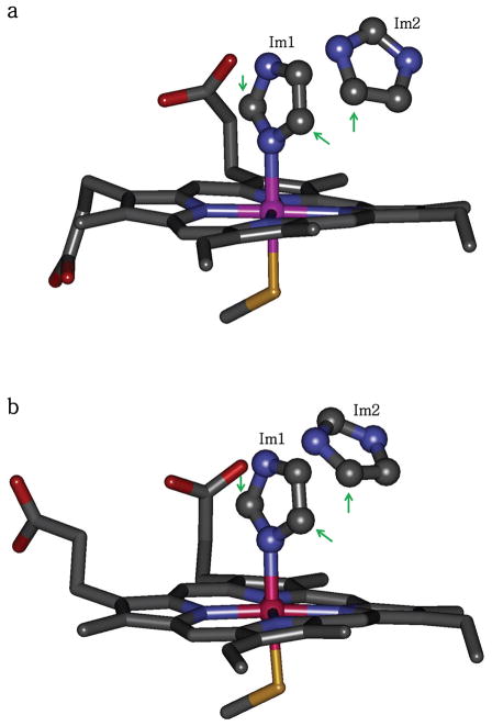
The numerical simulations of the ENDOR spectra were performed using the program SimBud available for download at http://www.cbc.arizona.edu/facilities/epr_facility_software. The simulations were based on a structural model formulated from X-ray crystal structures of iNOS heme domain with coordinated imidazole (Figure 1).49
Figure 1.
Heme active sites in murine iNOS heme domain structures (a) 1NOS and (b) 1NOC, which are the only available structures of imidazole-bound iNOS. There are two nearby imidazole molecules in the active site: Im1 (coordinated to the heme iron) and Im2 (H-bonded to Glu371). Note that the positions of Im2 are different in the two structures. The arrows point at the carbon atoms whose bound hydrogens (D2 and D5 of Im1 and D5 of Im2) make the largest contributions to the observed ENDOR spectra in this study.
Results and discussion
1. Experimental results
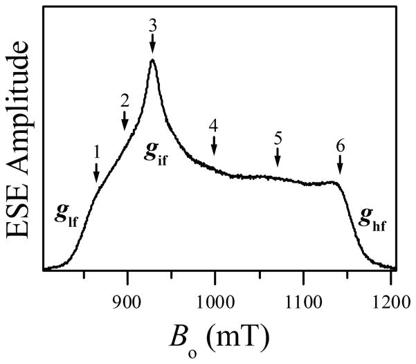
Figure 2 shows the Ka-band field sweep ESE spectrum of the imidazole-coordinated heme center of iNOS oxyFMN. The spectrum is obtained using the three-pulse (stimulated) ESE sequence. The principal g-values determined from this spectrum are (ghf, gif, glf) = (1.86, 2.30, 2.52), where the subscripts “hf”, “if”, and “lf” stand for “high field”, “intermediate field”, and “low field”, respectively. The arrows with numbers indicate the EPR positions used for pulsed ENDOR experiments. The determined g-values are consistent with those obtained by us earlier31 and those determined for low-spin imidazole-bound heme of eNOS.50
Figure 2.
Three-pulse ESE field sweep spectrum of human iNOS oxyFMN with heme coordinated by imidazole. Experimental conditions: mw frequency, 29.966 GHz; mw pulses, 311 ns; time interval between the first and second mw pulses, τ= 180 ns; time interval between the second and third mw pulses, T = 4 μs; temperature, 10 K. Principal g-values corresponding to the low-field, intermediate-field and high-field turning points are denoted glf, gif, and ghf, respectively. The numbered arrows indicate the EPR positions used for pulsed ENDOR measurements; positions 1 through 6 correspond to Bo = 864.8, 897.8, 928.8, 999.8, 1070.3, and 1141.8 mT, respectively. The numbering of the arrows corresponds to that of the traces in the subsequent figures with ENDOR spectra.
As we were primarily interested in 2H ENDOR spectra, the Mims ENDOR technique was employed. The experiments were performed at the time interval between the first and second mw pulses τ = 360 ns. This interval was somewhat shorter than the optimum τ ~ 1 μs (given that the maximum observable deuterium splittings were about 0.7 MHz, see below), but the deep ESEEM from the heme and imidazole 14N nuclei did not provide much choice (see Figure S1 of Supporting Information). At τ = 360 ns, the first blind spot48,51 corresponds to the hfi constant A = 1/τ ≈ 2.8 MHz, much larger than the maximum hfi constant expected or observed in 2H ENDOR spectra of this system (see below).
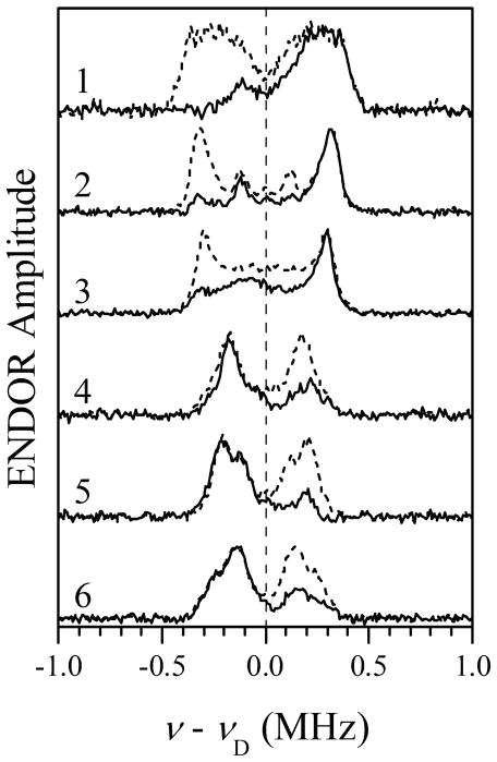
The difference 2H Mims ENDOR spectra were obtained as follows. The spectra were recorded for the samples with Im-D and Im-H, and normalized by the ESE signal amplitude without RF. After this, the spectra obtained for the protonated sample were subtracted from those obtained for the deuterated sample (the examples of both types of spectra are shown in Figure S2 of Supporting Information). The resulting 2H ENDOR spectra are presented in Figure 3 by solid traces. The dramatic lack of symmetry in these spectra with respect to the 2H Zeeman frequency, νD, is explained by the so-called implicit TRIPLE effect,52 which consists in non-uniform (with respect to the magnetic field orientations or electronic spin manifolds) suppression of the ENDOR effect caused by the extremely deep 14N ESEEM. In the present case, the effect is mostly that of significant suppression of the 2H ENDOR lines from one of the heme electron spin manifolds. Similar effect was previously observed in 1H Mims ENDOR spectra of Fe(III) tetraphenyl chlorine.46 Symmetrizing the spectra with respect to νD diminishes the implicit TRIPLE effects and approximately restores the traditional look of ENDOR spectra (dashed traces in Figure 3).
Figure 3.
2H Mims ENDOR spectra (solid traces) of iNOS oxyFMN with heme coordinated by imidazole. The spectra were obtained as differences between the normalized (by ESE amplitude without RF) spectra obtained in the samples with Im-D and Im-H (see Figure S2 in Supporting Information). Traces 1 through 6 correspond to the six EPR positions indicated in Figure 2 (Bo = 864.8, 897.8, 928.8, 999.8, 1070.3, and 1141.8 mT, respectively). Experimental conditions: mw frequency, 29.966 GHz; mw pulses, 3×11 ns; time interval between the first and second mw pulses, τ= 360 ns; time interval between the second and third mw pulses, T = 60μs; RF pulse, 55μs; temperature, 10 K. Dashed traces are obtained from the solid ones by symmetrization with respect to ν = νD.
2. Structural background for numerical simulations
Before considering the numerical simulations of the ENDOR spectra, a structural model was formulated based on the X-ray crystallographic information available in the literature. Only two crystal structures of iNOS heme domain with coordinated imidazole are available: pdb 1NOS and 1NOC, both for murine iNOS.49 Although these structures are of monomeric oxygenase domain lacking H4B and NH2-terminal residues 77 to 114, it is reasonable to expect that the imidazole positions will be the same in the truncated monomer and the active dimer, as the positions of the amino acid residues surrounding the heme center are the same in both cases. In addition, the high degree of structural conservation at the heme sites in murine and human iNOS makes it very probable that the main structural features related to the imidazole binding will also be conserved between these organisms. Therefore, we used the available X-ray structures of murine iNOS oxygenase domain with coordinated imidazole to facilitate the interpretation of the ENDOR data obtained here for human iNOS.
The analysis of pdb 1NOS and 1NOC shows that there are two imidazole molecules located at the heme site, Im1 and Im2 (Figure 1).49 Imidazole Im1 is coordinated to the heme iron, while Im2 is located above the edge of pyrrole ring A of the heme center and is hydrogen bonded to Glu371.49 One has to note that the heme pocket is more exposed in these truncated monomeric structures49 than in the iNOS dimer. While the position of Im1 is not likely to be affected by this difference, this is less certain for Im2. However, this is not significant because of the minimal effect of Im2 on the ENDOR spectra (see below).
The hydrogens at carbons C2, C4, and C5 (H2, H4, and H5, respectively) are non-exchangeable. Therefore, only these hydrogens (as deuterons) will contribute to the 2H ENDOR spectrum of iNOS prepared with Im-D in the H2O buffer. The distances from Fe(III) to these hydrogens are summarized in Table 1. Protons H2 and H5 of Im1 are located at the distance from the heme iron of RFeH = 3.25 ± 0.1 Å. They are the closest to the central Fe(III) ion and are expected to produce the largest splittings in the ENDOR spectra. Interestingly, H5 of Im2 is also located at a comparable distance (as low as 3.46 Å, see Table 1), although its position in the two crystal structures differs by about 0.7 Å. As these two structures correspond to different types of crystals (pdb 1NOS corresponds to the oxygenase domain alone, while pdb 1NOC corresponds to the iNOS oxygenase domain co-crystallized with Escherichia coli type I chloramphenicol acetyltransferase),49 this difference may indicate a possible inhomogeneity of the second imidazole position in frozen solutions (in particular, in our EPR samples).
Table 1.
Distances RFeH from Fe(III) to the protons of imidazole (Im) molecules extracted from pdb 1NOS and 1NOC. The corresponding anisotropic hfi constants T⊥H are calculated assuming ρFe = 1. The coordinated imidazole is Im1, while the second nearby imidazole is Im2 (for the sake of uniformity, the definitions of H4 and H5 of Im2 in the 1NOC column are swapped compared to those used in the pdb file).
| Hydrogen | RFeH from pdb 1NOS | T⊥H (T⊥D), MHz | RFeH from pdb 1NOC | T⊥H (T⊥D), MHz |
|---|---|---|---|---|
| H2 (Im1) | 3.31 Å | −2.18 (−0.33) | 3.35 Å | −2.10 (−0.32) |
| H4 (Im1) | 5.13 Å | −0.59 (−0.09) | 5.08 Å | −0.60 (−0.09) |
| H5 (Im1) | 3.23 Å | −2.34 (−0.36) | 3.16 Å | −2.50 (−0.38) |
| H2 (Im2) | 7.61 Å | −0.18 (−0.027) | 7.64 Å | −0.18 (−0.027) |
| H4 (Im2) | 5.25 Å | −0.55 (−0.08) | 6.19 Å | −0.33 (−0.05) |
| H5 (Im2) | 3.46 Å | −1.91 (−0.29) | 4.13 Å | −1.12 (−0.17) |
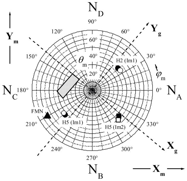
As described in the following section, deuterons D2 and D5 of Im1 and D5 of Im2 make the largest contribution to the amplitude of our 2H ENDOR spectra. The polar plot shown in Figure 4 indicates the angular positions of these three hydrogens with respect to the molecular coordinate frame (Xm, Ym, Zm), where axes Xm and Ym are in the heme plane and aligned with the Fe-N directions, and axis Zm coincides with the heme plane normal. One can see that all of these hydrogens are located at the polar angles θm~ 40°. The azimuthal angles, ϕm, for H2 and H5 of Im1 differ by about 180°, as expected from the planar structure of imidazole. For H5 of Im2, the azimuthal angle differs by ~90° from those of the hydrogens of Im1.
Figure 4.
Polar diagram showing the angular positions of H2 and H5 of Im1, H5 of Im2, and N10 of FMN with respect to the molecular coordinated system (Xm, Ym, Zm) of the heme center. The directions of Xm and Ym are indicated, and Zm is normal to the heme plane. Xg and Yg are the principal axes of the g-tensor, and their directions shown by dashed lines are determined in this work. The third axis of the g-frame, Zg, is perpendicular to the heme plane and parallel to Zm. The positions of hydrogens indicated by the filled symbols are derived from pdb 1NOS, while those indicated by the open symbols are derived from pdb 1NOC. The angular position of N10 of FMN (indicated by filled triangle) was obtained from the docking structure31 and reflected with respect to the heme plane (to facilitate comparison with the magnetic resonance data which do not distinguish between θ and 180°-θ). The shaded tetragonal area in the second and third quadrants represents the FMN position as estimated from the combined data obtained in RIDME experiments31 and this work. NA through ND atoms are the heme pyrrole nitrogens.
In addition to the molecular axes system, Figure 4 introduces the principal axes system of the g-factor (Xg, Yg, Zg), with axis Zg coinciding with the heme plane normal (and thus being parallel with the molecular axis Zm), and the (Xg, Yg) plane coinciding with the heme plane. The orientation of Xg and Yg with respect to Xm and Ym was not known in advance, and has been determined in this work.
3. Numerical simulations of the ENDOR spectra
In this section we perform numerical simulations of the 2H Mims ENDOR spectra aimed at establishing the orientation of the axis of glf with respect to the heme plane. The estimated anisotropic hfi constants T⊥H (T⊥D) of various protons (deuterons) belonging to Im1 and Im2 are summarized in Table 1. In these estimates, the spin population of Fe(III) was assumed to be ρFe = 1. The hfi for all of the protons is expected to be predominantly anisotropic, although some minor isotropic contribution can be expected for H2 and H5 of Im1.53 Therefore, the largest splittings in our ENDOR spectra (~ 0.7 MHz) should mostly arise from D2 and D5 of Im1. D5 of Im2 may also contribute to the large splittings. On average, however, the contribution of this deuteron to the ENDOR amplitude should not be more than half of the combined contribution of D2 and D5 of Im1 because under our experimental conditions the multinuclear effects54 can be neglected, and the ENDOR amplitude for the non-matrix lines is simply proportional to the number of nuclei. With the possible statistical distribution of RFeH for D5 of Im2 discussed above, its contribution to the large ENDOR splittings is likely to be even less.
The remaining three deuterons (D4 of Im1 and D2, D4 of Im2) are located at the distances exceeding 5 Å (see Table 1) and are responsible for the inner parts of the ENDOR spectra (splittings < 0.3 MHz). Under our experimental conditions (τ= 360 ns, the first maximum in Mims ENDOR response corresponds to A = 1/(2τ) ≈ 1.39 MHz48,51), the contribution of each of these remote deuterons to the ENDOR amplitude is significantly smaller than that from the “proximal” deuterons discussed above.
Based on these considerations, the following stepwise strategy was implemented. At the first step, benchmark calculations of ENDOR spectra for various possible orientations of the g-frame with respect to the molecular frame were performed using the structural data for D2 and D5 of Im1. A qualitative comparison of these spectra with the experimental ones was used to select the orientation of the glf axis with respect to the heme plane. At the second step, this general assignment was used to fit the external regions of the experimental spectra neglecting all of the deuterons except D2 and D5 of Im1. Finally, at the third step, D5 of Im2 was included into consideration in order to evaluate its effect on the spectra and to make conclusions about the validity of the calculation made in the second step. These three steps are described in detail below.
In the numerical simulations, the axial hfi and nqi tensor were used. The orientation of the hfi tensor axis with respect to the g-frame was described by the polar and azimuthal angles, θh and ϕh, respectively. Similarly, the orientation of the nqi axis was described by the angles θq and ϕq. This axis is with good accuracy parallel to the C–D bond. The D2 and D5 deuterons of Im1 were assumed to be spectroscopically equivalent, with θh = 40° and θq = 105°.
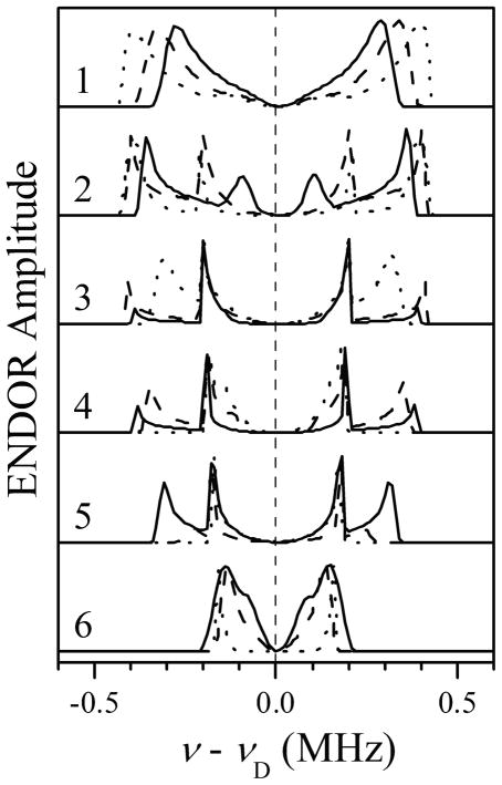
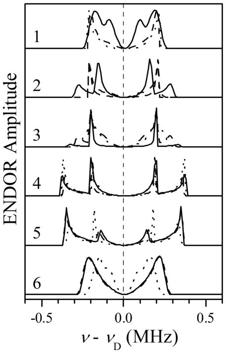
First, we utilized the structural data of Table 1 and Figure 4 to perform model 2H ENDOR calculations that were used as a benchmark for comparison with the experimental spectra. These benchmark calculations were performed for T⊥D = − 0.35 MHz (corresponds to RFeH = 3.25 Å and ρFe = 1). The quadrupole coupling constant for imidazole deuterons is e2Qq/h ≈ 0.18 MHz,55 but in the benchmark calculations (Figures 5 and 6) e2Qq/h = 0 was used. The reason for neglecting the nqi in these calculations is as follows. According to the Im1 coordination geometry, the difference between the angles θh and θq of D2(5) is about 65°. Therefore, when the vector of the external magnetic field, Bo, is parallel to RFeH (which corresponds to the largest hfi splitting), the nqi axis is approximately at the magic angle to Bo, and the nqi splitting is negligible. In the simulations aimed at actually fitting the experimental spectra (Figures 7 and 8 below), however, the nqi is taken into account (see the captions of the figures).
Figure 5.
Benchmark simulations of 2H Mims ENDOR spectra for D2 and D5 of Im1, assuming glf to correspond to the g-frame axis Zg (//Zm). The orientation of the Im1 plane with respect to the g-frame was characterized by azimuthal angles ϕh = 0 (solid traces), 45° (long-dashed traces), and 90° (short-dashed traces). Simulation parameters: aiso = 0 MHz; T⊥ = −0.35 MHz; e2Qq/h = 0 MHz; mw frequency, 29.966 GHz; τ= 360 ns; Bo = 864.8, 897.8, 928.8, 999.8, 1070.3, and 1141.8 mT for traces 1 through 6, respectively.
Figure 6.
Benchmark simulations of 2H Mims ENDOR spectra for D2 and D5 of Im1, assuming ghf to correspond to the g-frame axis Zg (//Zm). The orientation of the Im1 plane with respect to the g-frame was characterized by azimuthal angles ϕh = 0° (solid traces), 45° (long-dashed traces), and 90° (short-dashed traces). Simulation parameters: aiso = 0 MHz; T⊥ = −0.35 MHz; e2Qq/h = 0 MHz; mw frequency, 29.966 GHz; τ = 360 ns; Bo = 864.8, 897.8, 928.8, 999.8, 1070.3, and 1141.8 mT for traces 1 through 6, respectively.
Figure 7.
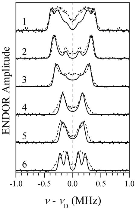
Simulations of 2H Mims ENDOR spectra for D2 and D5 of Im1 (solid traces), assuming ghf to correspond to the g-frame axis Zg (//Zm). The orientation of the Im1 plane with respect to the g-frame was characterized by the azimuthal angle ϕh = 80. Simulation parameters: aiso = −0.04 MHz; T⊥ = −0.32 MHz; e2Qq/h = 0.18 MHz; η = 0; mw frequency, 29.966 GHz; τ = 360 ns; Bo = 864.8, 897.8, 928.8, 999.8, 1070.3, and 1141.8 mT for traces 1 through 6, respectively. The simulated spectra were convoluted with a Gaussian line with the width of 0.05 MHz between the maximum slope points. Dashed traces, symmetrized experimental spectra reproduced from Figure 3.
Figure 8.
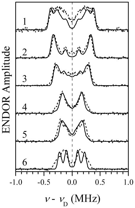
Simulations of 2H Mims ENDOR spectra for D2 and D5 of Im1 and D5 of Im2 (solid traces), assuming ghf to correspond to the g-frame axis Zg (//Zm). The simulation parameters for D2 and D5 of Im1 are the same as those in Figure 7. Simulation parameters for D5 of Im2: aiso = 0 MHz; T⊥ = −0.18 MHz; e2Qq/h = 0.18 MHz; η= 0; θh = 44°; ϕh = −5°; θq = 60°; ϕq = 20°. Other simulation parameters are the same as in Figure 7. The simulated spectra were convoluted with a Gaussian line with the width of 0.05 MHz between the maximum slope points. Dashed traces, symmetrized experimental spectra reproduced from Figure 3.
Figure 5 shows the 2H ENDOR spectra calculated assuming the axis of glf being perpendicular to the heme plane (i.e., coinciding with Zg//Zm). The principal axes Xg and Yg are defined to coincide with the axes of ghf and gif, respectively. The orientation of the Im1 plane with respect to axes Xg and Yg in these calculations was characterized by the azimuthal angle ϕh, which is also the azimuthal angle of the hfi tensor axis for H2(5) of Im1. The three sets of calculated spectra shown in Figure 5 by solid, long-dashed, and short-dashed lines correspond to ϕh = 0°, 45°, and 90°, respectively. One can see that this arrangement of the principal g-axes results in the largest splittings in the ENDOR spectra being observed for the EPR positions between glf and gif. The alternative situation of the axis of ghf being perpendicular to the heme plane is presented in Figure 6. In this case, the largest ENDOR splittings are observed for the EPR positions between gif and ghf.
In the experimental spectra (Figure 3), the largest ENDOR splitting is attained for trace 2, between glf and gif. According to the calculations presented in Figures 5 and 6, this indicates that the axis of glf is perpendicular to the heme plane, while the axis of ghf is in the plane. This assignment of glf to Zg naturally explains the fact that the scale of the ENDOR splittings observed for D2 and D5 of Im1 in this work, as well as the overall dependence of these splittings on the EPR position, are similar to those observed earlier for bis-imidazole (or histidine) coordinated heme centers.56
Our next step was to perform numerical simulations for D2 and D5 of Im1 in order to reproduce the external regions of the experimental ENDOR spectra, and thus to determine ϕh and obtain a more accurate estimate of the spectroscopic parameters. As mentioned above, in these simulations D2 and D5 of Im1 were assumed to be spectroscopically equivalent, and the 2H nqi with e2Qq/h = 0.18 MHz and the asymmetry parameter η = 0 (corresponds to the axial nqi tensor) was taken into account. The variable parameters of the simulation were T⊥D, aiso, and ϕh = ϕq. The starting hfi parameters were those used in calculations presented in Figures 5 and 6.
Solid traces in Figure 7 represent the spectra simulated for T⊥D = −0.32 MHz, aiso = −0.04 MHz, e2Qq/h = 0.18 MHz, η= 0, ϕh = ϕq = 80°. To approximate the experimental intrinsic linewidth, the simulated spectra were convoluted with the Gaussian function with the width between the maximum slope points of 0.05 MHz. The short-dashed traces in Figure 7 show the symmetrized experimental spectra. The simulated and experimental spectra are in qualitative agreement. The most dramatic discrepancy is the presence of well-resolved splittings in the simulated spectrum 6, where the experimental spectrum shows only weakly resolved peaks. This difference is caused by the constraints of our simulation model, mostly, the spectroscopic equivalence of D2 and D5 of Im1 and the complete absence of structural disorder. From T⊥D ≈ −0.32 MHz the spin population of the central Fe(III) ion can be estimated as ρFe ≈ 0.9.
Finally, the effect of D5 of Im2 on the simulated ENDOR spectra was evaluated. In these simulations, the parameters of D2 and D5 of Im1 estimated above were used. Trial simulations have shown that for the EPR positions between glf and gif the effect of the additional deuteron is minimal within the whole range of variation of distances indicated in Table 1. At EPR positions 4 and 5, however, the ENDOR splitting from this deuteron has significantly exceeded the experimental splittings for |T⊥D| > 0.18 MHz (RFeH < 3.9 Å, assuming ρFe ~ 0.9). Therefore, for the model with fixed geometry (without a statistical distribution of distances) RFeH ~ 3.9 Å represents the shortest possible distance from Fe to D5 of Im2. If a distribution RFeH is assumed, then the minimal distance can be somewhat shorter (just how much shorter will depend on the specific distribution model). As an example, Figure 8 shows the result of simulations with D5 of Im2 having T⊥D = −0.18 MHz. Note that the spectra of Figure 8 are nearly identical to those of Figure 7, in which D5 of Im2 was not taken into account. This comparison validates the results of numerical simulations for D2 and D5 of Im1 above.
While better agreement between the simulated and experimental spectra could probably be achieved if the structural (strictly equivalent D2 and D5 deuterons) and spectroscopic (axial hfi tensors) constraints were removed, and the implicit TRIPLE effects taken into account, such an improvement would be purely cosmetic, and we did not attempt to achieve it.
The analysis of the experimental g-values of the Im-coordinated heme center of NOS using the expressions derived by Taylor57 results in the axis of ghf being the natural quantization axis for the d-orbitals (so-called proper Z axis), ZQ. Although this axis is parallel to the heme plane (as established in this work), the unpaired electron predominantly resides in the out-of-plane d-orbitals, and thus the orbital state of Fe(III) can be characterized as dπ. The results of the analysis are summarized in the Supporting Information, Table S1.
It is interesting to compare the combined experimental results obtained here and in our previous work31 with the results of the computational docking studies.31 The filled triangle in the third quadrant of the polar plot of Figure 4 shows the orientation of the radius-vector RFe-FMN joining the heme iron and N10 of FMNH• (the closest atom with major spin population) with respect to the heme molecular frame, as obtained from the docking model.31 The dashed lines show the axes Xg and Yg that correspond to the angle ϕh between Xg and Im1 plane of 80° (actually, there are two possible orientations differing by Δϕm ≈ 20°; the shown orientation provides a better agreement between the experimental and calculated orientations of RFe-FMN in the g-frame). The shaded tetragonal area extending from the second to the third quadrant represents the range of RFe-FMN orientations obtained by combining the results of RIDME measurements31 (orientation of RFe-FMN with respect to the g-frame) with the results of this work (orientation of the g-frame with respect to the heme molecular frame).
As seen in Figure 4, the smallest differences between the RFe-FMN orientations obtained from RIDME and from computational docking in both θ and ϕ are ~20°. Apart from the uncertainty in the determined orientation of Xg and Yg with respect to the Im1 plane (about ±5°), several other possible factors can contribute to this discrepancy. First, Figure 4 actually combines the spectroscopic data obtained for human iNOS with the X-ray structural data obtained for murine iNOS. Although we expect the structure of the imidazole-bound heme site to be similar in both organisms, some angular differences can be anticipated. The scale of these differences can be estimated as about 10° from comparison of the orientations of the Sγ-Cβ bond of the cysteine ligand in human and murine iNOS oxygenase domains (pdb 1NSI and 1NOD, respectively). Second, the docking calculations31 used the X-ray structures of the heme and FMN domains without any modifications. The assumption of rigid structures might not entirely correspond to the reality. In fact, our recent MCD studies indicate that the FMN domain docking affects the heme site structure,29,30 and the same might also be true for the FMN site. The dependence of the Im2 position on the specific crystal packing discussed above also provides evidence of some structural variability within the heme domain caused by external (e.g., interdomain) interactions. Therefore, some relative positional and/or orientational shifts of the heme and FMN cofactors with respect to the calculated docking structure may be expected. The third factor to take into account is that the axis of glf is not bound to be exactly parallel to Zm. In fact, distortions of the heme conformation and axial ligand coordination geometry usually lead to misalignment of the direction of the (average) heme plane normal and that of the out-of plane g-factor axis by a few (up to ~15°) degrees.58,59 Finally, the limits of possible orientations of RFe-FMN with respect to the g-frame in our previous work31 were established rather approximately because a 30° grid was used for the azimuthal angle ϕ (as defined in ref. 31; with definitions of this work it mostly translates to θm). Additional simulations for the orientations between the grid angles show that a marginal agreement between the experimental and simulated RIDME spectra is possible for the angles up to (θm, ϕm) ~ (50°, 200°), which would reduce the difference between the experimental and calculated orientations of RFe-FMN to about 10°.
Taken separately, each of the above structural factors is unlikely to be responsible for the difference between the experimental results and the predictions of the docking calculations: e.g., the 20° orientational difference at RFe-FMN ~ 18.8 Å results in a translational shift of ~ 6.5 Å, which seems somewhat excessive. However a combination of these factors can readily reconcile the experimental and computational results assuming changes in parameters within error limits of their definition or determination (see above). Therefore, from these considerations we conclude that the docking model obtained earlier31 is in qualitative agreement with the previous experimental results31 and those obtained in this work.
Finally, it is of note that according to the docking model calculated in our previous work,31 the angle between the heme and FMN planes is about 10°. It was deduced above that the singly occupied orbital of Fe(III) is essentially dπ, i.e., the orbital strongly interacting with the π-system of the porphyrin ligand. The combination of this orbital configuration, the angle between the heme and FMN molecular planes, and the orientation of RFe-FMN at a large angle to the heme plane normal provide the electronic and structural conditions for efficient FMN–heme IET.60
Conclusion
The results obtained in this work represent a logical continuation of the structural determination related to the relative spatial arrangement of FMN and heme centers in the docked state of NOS protein, which was started in our previous work.31 The aforementioned results31 and this work provide structural constraints for validation of computational docking models, and the selected docking model31 was found to be in qualitative agreement with the combined experimental results of the two pulsed EPR works.
Supplementary Material
Acknowledgments
We thank Prof. Brian Crane at Cornell University for helpful discussions. This work was supported by grants from the National Institutes of Health (GM081811 and HL091280 to C.F.), AHA Grant-in-Aid (09GRNT2220310 to C.F.), and NSERC (183521 to J.G.G.). The project described was also supported by Grant Number P20RR016480 from the National Center for Research Resources (NCRR), a component of the National Institutes of Health. CF acknowledges the support of UNM HSC RAC grant.
Abbreviations
- NO
nitric oxide
- NOS
nitric oxide synthase
- iNOS
inducible NOS
- CaM
calmodulin
- oxyFMN
bi-domain NOS construct in which only oxygenase and FMN domains along with CaM-binding region are present
- FMN
flavin mononucleotide
- FMNH•
FMN semiquinone
- IET
interdomain electron transfer
- EPR
electron paramagnetic resonance
- ESE
electron spin echo
- ENDOR
electron-nuclear double resonance
- ESEEM
electron spin echo envelope modulation
- RIDME
relaxation-induced dipolar modulation enhancement
- mw
microwave
Footnotes
SUPPORTING INFORMATION. Stimulated ESEEM of the human iNOS heme center as a function of τ; example of Mims ENDOR spectra obtained with Im-D and Im-H; Fe(III) d-orbital coefficients obtained from the analysis of the heme center principal g-values.
References
- 1.Roman LJ, Martasek P, Masters BSS. Chem Rev. 2002;102:1179–1189. doi: 10.1021/cr000661e. [DOI] [PubMed] [Google Scholar]
- 2.Alderton WK, Cooper CE, Knowles RG. Biochem J. 2001;357:593–615. doi: 10.1042/0264-6021:3570593. [DOI] [PMC free article] [PubMed] [Google Scholar]
- 3.Abu-Soud HM, Yoho LL, Stuehr DJ. J Biol Chem. 1994;269:32047–32050. [PubMed] [Google Scholar]
- 4.Abu-Soud HM, Stuehr DJ. Proc Natl Acad Sci U S A. 1993;90:10769–10772. doi: 10.1073/pnas.90.22.10769. [DOI] [PMC free article] [PubMed] [Google Scholar]
- 5.Panda K, Ghosh S, Stuehr DJ. J Biol Chem. 2001;276:23349–23356. doi: 10.1074/jbc.M100687200. [DOI] [PubMed] [Google Scholar]
- 6.Crane BR, Arvai AS, Ghosh DK, Wu CQ, Getzoff ED, Stuehr DJ, Tainer JA. Science. 1998;279:2121–2126. doi: 10.1126/science.279.5359.2121. [DOI] [PubMed] [Google Scholar]
- 7.Santolini J. J Inorg Biochem. 2011;105:127–141. doi: 10.1016/j.jinorgbio.2010.10.011. [DOI] [PubMed] [Google Scholar]
- 8.Daff S. Nitric Oxide. 2010;23:1–11. doi: 10.1016/j.niox.2010.03.001. [DOI] [PubMed] [Google Scholar]
- 9.Zhu Y, Silverman RB. Biochemistry. 2008;47:2231–2243. doi: 10.1021/bi7023817. [DOI] [PubMed] [Google Scholar]
- 10.Davydov R, Sudhamsu J, Lees NS, Crane BR, Hoffman BM. J Am Chem Soc. 2009;131:14493–14507. doi: 10.1021/ja906133h. [DOI] [PubMed] [Google Scholar]
- 11.Woodward JJ, NejatyJahromy Y, Britt RD, Marletta MA. J Am Chem Soc. 2010;132:5105–5113. doi: 10.1021/ja909378n. [DOI] [PubMed] [Google Scholar]
- 12.Li D, Kabir M, Stuehr DJ, Rousseau DL, Yeh SR. J Am Chem Soc. 2007;129:6943–6951. doi: 10.1021/ja070683j. [DOI] [PubMed] [Google Scholar]
- 13.Feng CJ, Tollin G. Dalton Trans. 2009:6692–6700. doi: 10.1039/b902884f. [DOI] [PMC free article] [PubMed] [Google Scholar]
- 14.Stuehr DJ, Tejero J, Haque MM. FEBS J. 2009;276:3959–3974. doi: 10.1111/j.1742-4658.2009.07120.x. [DOI] [PMC free article] [PubMed] [Google Scholar]
- 15.Dunford AJ, Rigby SEJ, Hay S, Munro AW, Scrutton NS. Biochemistry. 2007;46:5018–5029. doi: 10.1021/bi7001339. [DOI] [PubMed] [Google Scholar]
- 16.Noble MA, Munro AW, Rivers SL, Robledo L, Daff SN, Yellowlees LJ, Shimizu T, Sagami I, Guillemette JG, Chapman SK. Biochemistry. 1999;38:16413–16418. doi: 10.1021/bi992150w. [DOI] [PubMed] [Google Scholar]
- 17.Gao YT, Smith SME, Weinberg JB, Montgomery HJ, Newman E, Guillemette JG, Ghosh DK, Roman LJ, Martasek P, Salerno JC. J Biol Chem. 2004;279:18759–18766. doi: 10.1074/jbc.M308936200. [DOI] [PubMed] [Google Scholar]
- 18.Daff S, Noble MA, Craig DH, Rivers SL, Chapman SK, Munro AW, Fujiwara S, Rozhkova E, Sagami I, Shimizu T. Biochem Soc Trans. 2001;29:147–152. doi: 10.1042/0300-5127:0290147. [DOI] [PubMed] [Google Scholar]
- 19.Sanae R, Kurokawa F, Oda M, Ishijima S, Sagami I. Biochemistry. 2011;50:1714–1722. doi: 10.1021/bi101575u. [DOI] [PubMed] [Google Scholar]
- 20.Welland A, Garnaud PE, Kitamura M, Miles CS, Daff S. Biochemistry. 2008;47:9771–9780. doi: 10.1021/bi800787m. [DOI] [PubMed] [Google Scholar]
- 21.Xia C, Misra I, Iyanagi T, Kim JJP. J Biol Chem. 2009;284:30708–30717. doi: 10.1074/jbc.M109.031682. [DOI] [PMC free article] [PubMed] [Google Scholar]
- 22.Li W, Fan W, Elmore BO, Feng C. FEBS Lett. 2011 doi: 10.1016/j.febslet.2011.07.022. in press. [DOI] [PMC free article] [PubMed] [Google Scholar]
- 23.Feng CJ, Taiakina V, Ghosh DK, Guillemette J, Tollin G. Biochimica et Biophysica Acta (BBA)-Proteins & Proteomics. 2011 doi: 10.1016/j.bbapap.2011.08.004. in press. [DOI] [PMC free article] [PubMed] [Google Scholar]
- 24.Feng C, Fan W, Dupont A, Guy Guillemette J, Ghosh DK, Tollin G. FEBS Lett. 2010;584:4335–4338. doi: 10.1016/j.febslet.2010.09.028. [DOI] [PMC free article] [PubMed] [Google Scholar]
- 25.Feng CJ, Roman LJ, Hazzard JT, Ghosh DK, Tollin G, Masters BSS. FEBS Lett. 2008;582:2768–2772. doi: 10.1016/j.febslet.2008.07.005. [DOI] [PMC free article] [PubMed] [Google Scholar]
- 26.Feng CJ, Tollin G, Hazzard JT, Nahm NJ, Guillemette JG, Salerno JC, Ghosh DK. J Am Chem Soc. 2007;129:5621–5629. doi: 10.1021/ja068685b. [DOI] [PubMed] [Google Scholar]
- 27.Feng CJ, Tollin G, Holliday MA, Thomas C, Salerno JC, Enemark JH, Ghosh DK. Biochemistry. 2006;45:6354–6362. doi: 10.1021/bi060223n. [DOI] [PubMed] [Google Scholar]
- 28.Feng CJ, Thomas C, Holliday MA, Tollin G, Salerno JC, Ghosh DK, Enemark JH. J Am Chem Soc. 2006;128:3808–3811. doi: 10.1021/ja0578606. [DOI] [PubMed] [Google Scholar]
- 29.Sempombe J, Galinato MGI, Elmore BO, Fan W, Guillemette JG, Lehnert N, Kirk ML, Feng C. Inorg Chem. 2011;50:6859–6861. doi: 10.1021/ic200952c. [DOI] [PMC free article] [PubMed] [Google Scholar]
- 30.Sempombe J, Elmore BO, Sun X, Dupont A, Ghosh DK, Guillemette JG, Kirk ML, Feng C. J Am Chem Soc. 2009;131:6940–6941. doi: 10.1021/ja902141v. [DOI] [PMC free article] [PubMed] [Google Scholar]
- 31.Astashkin AV, Elmore BO, Fan W, Guillemette JG, Feng C. J Am Chem Soc. 2010;132:12059–12067. doi: 10.1021/ja104461p. [DOI] [PMC free article] [PubMed] [Google Scholar]
- 32.Page CC, Moser CC, Chen XX, Dutton PL. Nature. 1999;402:47–52. doi: 10.1038/46972. [DOI] [PubMed] [Google Scholar]
- 33.Raman CS, Li HY, Martasek P, Kral V, Masters BSS, Poulos TL. Cell. 1998;95:939–950. doi: 10.1016/s0092-8674(00)81718-3. [DOI] [PubMed] [Google Scholar]
- 34.Li HY, Shimizu H, Flinspach M, Jamal J, Yang WP, Xian M, Cai TW, Wen EZ, Jia QA, Wang PG, Poulos TL. Biochemistry. 2002;41:13868–13875. doi: 10.1021/bi020417c. [DOI] [PubMed] [Google Scholar]
- 35.Zhang J, Martasek P, Paschke R, Shea T, Masters BSS, Kim JJP. J Biol Chem. 2001;276:37506–37513. doi: 10.1074/jbc.M105503200. [DOI] [PubMed] [Google Scholar]
- 36.Garcin ED, Bruns CM, Lloyd SJ, Hosfield DJ, Tiso M, Gachhui R, Stuehr DJ, Tainer JA, Getzoff ED. J Biol Chem. 2004;279:37918–37927. doi: 10.1074/jbc.M406204200. [DOI] [PubMed] [Google Scholar]
- 37.Aoyagi M, Arvai AS, Tainer JA, Getzoff ED. EMBO J. 2003;22:766–775. doi: 10.1093/emboj/cdg078. [DOI] [PMC free article] [PubMed] [Google Scholar]
- 38.Kulik LV, Dzuba SA, Grigoryev IA, Tsvetkov YD. Chem Phys Lett. 2001;343:315–324. [Google Scholar]
- 39.Ghosh DK, Holliday MA, Thomas C, Weinberg JB, Smith SME, Salerno JC. J Biol Chem. 2006;281:14173–14183. doi: 10.1074/jbc.M509937200. [DOI] [PubMed] [Google Scholar]
- 40.Feng CJ, Dupont A, Nahm N, Spratt D, Hazzard JT, Weinberg J, Guillemette J, Tollin G, Ghosh DK. J Biol Inorg Chem. 2009;14:133–142. doi: 10.1007/s00775-008-0431-2. [DOI] [PMC free article] [PubMed] [Google Scholar]
- 41.Safo MK, Walker FA, Raitsimring AM, Walters WP, Dolata DP, Debrunner PG, Scheidt WR. J Am Chem Soc. 1994;116:7760–7770. [Google Scholar]
- 42.Walker FA, Nasri H, Turowska-Tyrk I, Mohanrao K, Watson CT, Shokhirev NV, Debrunner PG, Scheidt WR. J Am Chem Soc. 1996;118:12109–12118. [Google Scholar]
- 43.Astashkin AV, Raitsimring AM, Kennedy AR, Shokhireva TK, Walker FA. J Phys Chem A. 2002;106:74–82. [Google Scholar]
- 44.Raitsimring AM, Walker FA. J Am Chem Soc. 1998;120:991–1002. [Google Scholar]
- 45.Astashkin AV, Raitsimring AM, Walker FA. Chem Phys Lett. 1999;306:9–17. [Google Scholar]
- 46.Astashkin AV, Raitsimring AM, Walker FA. J Am Chem Soc. 2001;123:1905–1913. doi: 10.1021/ja002777y. [DOI] [PubMed] [Google Scholar]
- 47.Astashkin AV, Enemark JH, Raitsimring A. Concepts in Magnetic Resonance Part B-Magnetic Resonance Engineering. 2006;29B:125–136. [Google Scholar]
- 48.Mims WB. Proceedings of the Royal Society of London Series A Mathematical and Physical Sciences. 1965;283:452–457. [Google Scholar]
- 49.Crane BR, Arvai AS, Gachhui R, Wu CQ, Ghosh DK, Getzoff ED, Stuehr DJ, Tainer JA. Science. 1997;278:425–431. doi: 10.1126/science.278.5337.425. [DOI] [PubMed] [Google Scholar]
- 50.Tsai AL, Berka V, Chen PF, Palmer G. J Biol Chem. 1996;271:32563–32571. doi: 10.1074/jbc.271.51.32563. [DOI] [PubMed] [Google Scholar]
- 51.Gemperle C, Schweiger A. Chem Rev. 1991;91:1481–1505. [Google Scholar]
- 52.Doan PE, Nelson MJ, Jin H, Hoffman BM. J Am Chem Soc. 1996;118:7014–7015. [Google Scholar]
- 53.Satterlee JD, La Mar GN. J Am Chem Soc. 1976;98:2804–2808. doi: 10.1021/ja00439a027. [DOI] [PubMed] [Google Scholar]
- 54.Astashkin AV, Kawamori A. J Magn Reson. 1998;135:406–417. doi: 10.1006/jmre.1998.1568. [DOI] [PubMed] [Google Scholar]
- 55.Garcia MLS, Smith JAS, Bavin PMG, Ganellin CR. J Chem Soc, Perkin Trans. 1983;2:1391–1399. [Google Scholar]
- 56.Scholes CP, Falkowski KM, Chen S, Bank J. J Am Chem Soc. 1986;108:1660–1671. [Google Scholar]
- 57.Taylor CPS. Biochimica et Biophysica Acta (BBA)-Protein Structure. 1977;491:137–148. doi: 10.1016/0005-2795(77)90049-6. [DOI] [PubMed] [Google Scholar]
- 58.Saitoh T, Tachibana Y, Higuchi Y, Hori H, Akutsu H. Bull Chem Soc Jpn. 2004;77:357–363. [Google Scholar]
- 59.Byrn MP, Katz BA, Keder NL, Levan KR, Magurany CJ, Miller KM, Pritt JW, Strouse CE. J Am Chem Soc. 1983;105:4916–4922. [Google Scholar]
- 60.Cave RJ, Klippenstein SJ, Marcus RA. J Chem Phys. 1986;84:3089–3098. [Google Scholar]
Associated Data
This section collects any data citations, data availability statements, or supplementary materials included in this article.


