

Abstract
A significant challenge to the field of biofabrication is the rapid construction of large three dimensional (3D) living tissues and organs. Multi-cellular spheroids have been used as building blocks. In this paper, we create large multi-cellular honeycomb building blocks using directed self-assembly, whereby cell-to-cell adhesion, in the context of the shape and obstacles of a micromold, drives the formation of a 3D structure. Computer aided design, rapid prototyping and replica molding were used to fabricate honeycomb-shaped micro-molds. Nonadhesive hydrogels cast from these micro-molds were equilibrated in cell culture medium and seeded with two types of mammalian cells. The cells settled into the honeycomb recess, were unable to attach to the nonadhesive hydrogel and so cell-to-cell adhesion drove the self-assembly of a large multicellular honeycomb within 24 hours. Distinct morphological changes occurred to the honeycomb and its cells indicating the presence of significant cell-mediated tension. Unlike the spheroid, whose size is constrained by a critical diffusion distance needed to maintain cell viability, the overall size of the honeycomb is not limited. The rapid production of the honeycomb building unit, with its multiple rings of high density cells and open lumen spaces, offers interesting new possibilities for biofabrication strategies.
Keywords: microtissues, 3D cell culture, honeycomb, self-assembly, hydrogel
Introduction
One approach in the field of biofabrication or bioprinting uses a modification of inkjet printing or rapid prototyping technologies to fabricate mammalian tissue constructs layer-by-layer via printing living cells along with an extracellular matrix-like material [1-7]. Computer control of the deposition process facilitates the fabrication of large complex shaped structures. A key component in this fabrication process is the cellular building unit and typical approaches use either mono-dispersed cells or aggregates of 100s to 1000s of cells known as spheroids. As a building unit, the spheroid has several potential advantages over mono-dispersed cells. The spheroid has a high density of closely packed cells akin to the cell density of natural tissues and organs. The bioprinting or placement of a single spheroid of 1,000 cells is significantly faster than the placement of 1,000 individual cells. The spheroid has well established cell-to-cell contacts that can preserve cell viability and promote cell function. Moreover, the spheroid can fuse with other spheroids and/or attach to extracellular matrix material. The overall size of the spheroid, however, is limited by the diffusion of oxygen, nutrients and metabolic waste products (∼100-200μm) in order to maintain viability [8-10]. And, the spherical shape of the spheroid limits its ability to replicate or fabricate some of the more complex geometries found in vivo.
Another significant obstacle to the goal of fabricating large tissue structures containing high densities of cells is the limitation of diffusion and the need for a vascular tree. This is an area of very active research and there are numerous approaches to this problem including bioprinting of a vascular tree [3], microfabrication of a vascular network [11, 12], endothelialized collagen gel modules [13, 14], sequential layering of sheets of cells [15], scaffolds with microchannels for perfusion [16, 17], and self-assembly to form intermediate microvessels and fusion of prevascularized tissue-engineered constructs to the host vasculature [18-20].
It has been known for some time that cells, in the absence of a scaffold, will undergo a process known as self-assembly. In this process, mono-dispersed cells will spontaneously aggregate and form a three dimensional (3D) multi-cellular microtissue called a spheroid [21]. It is thought that self-assembly mimics natural processes that occur during embryogenesis, morphogenesis and organogenesis [21, 22]. Self-assembled spheroids have been formed from a variety of different cell types and mixtures of cell types [23-28].
Two methods have been predominately used for the self-assembly of spheroids; spinner culture [29] and hanging drop [23]. In spinner culture, mono-dispersed cells are pipetted into a flask and are prevented from attaching to a surface due to constant mixing. During this time, cells collide with one another and form multi-cellular spheroids. The size of the spheroids is roughly controlled by the concentration of cells added, their relative adhesiveness and the time in spinner culture. Large numbers of spheroids can be easily harvested however; spinner culture has several limitations. Self-assembly occurs in an environment with significant shear forces and so may not be useful for cells with low adhesiveness, sensitivity to shear forces, slow rates of self-assembly or a tendency to rapidly undergo apoptosis when detached (e.g., anoikis). And, the size range of spheroid diameters is broad.
In the hanging drop method, a small volume (∼50 μL) of mono-dispersed cells is pipetted onto a surface, (e.g., lid of tissue culture dish), and this surface is inverted so that the drop hangs under its own weight. The cells settle to the bottom of the drop, contact one another and undergo self-assembly. The use of an automatic multi-channel pipettor has enabled the production of large numbers of spheroids [23]. Spheroid size is readily controlled by the concentration of the cells in each drop and the range of distribution of sizes has been shown to be narrow. Likewise, cellular composition is easily controlled, spheroids of two or more cell types can be generated, and spheroids can be harvested. The method has two significant limitations. First, handling of hundreds of small drops can be challenging. Second, like spinner culture, the hanging drop produces only spheroids and so cannot direct the self-assembly of cells into complex geometries.
We have recently shown that self-assembly is not limited to spheroid-shaped microtissues [30]. Cells can self-assemble multi-cellular microtissues with complex shapes such as rods, toroids and even simple honeycombs. To achieve these shapes, mono-dispersed cells are seeded into micromolded hydrogels of nonadhesive materials such as agarose. The micro-molds, by virtue of their geometry, set the initial conditions and configuration of cells from which self-assembly commences and also impose obstacles (e.g., nonadhesive agarose pegs) that influence self-assembly. The outcome can be a structure far different from a simple spheroid structure. We refer to this process as directed self-assembly. Since the process is often completed within 24-48 hours, and since microtissues made in this way can be harvested and fused to form even larger structures [31], directed self-assembly may be useful for applications in biofabrication and 3D tissue engineering. In this paper, we show that directed self-assembly can be used to produce large multi-cellular honeycombs, which as a building block for biofabrication, potentially offers some distinct advantages over the spheroid.
Materials and Methods
Design, fabrication and casting of micro-molds
Micro-molds with honeycomb shaped features were fabricated as previously described [30-32]. Briefly, micro-molds were designed using computer-assisted design (CAD) (Solid Works Corporation – Concord, MA). The CAD drawings were the opposite (negative) of the final hydrogel (positive) which would receive the cells. Wax prototypes (negative) from the CAD files were produced with a ThermoJet® rapid prototyping machine (3D Systems Corporation - Valencia, CA). Due to the limitations of the resolution of the printer, about 30% of the wax molds were acceptable. Replicas were produced by coating the wax prototypes with a fast curing silicone based rubber (Reprorubber) (Flexbar Machine Corporation - Islandia, NY). After curing, Reprorubber replicas (positives) were removed from the wax prototypes, inverted and sprayed with Epoxy Parafilm release agent (Flexbar). These positives were filled with Sylgard 184 PDMS that was mixed according to the manufacturer's instructions (Dow Corning Corporation – Midland, MI), degassed to remove bubbles, and cured for 1.5 hours within the Reprorubber replica. The resulting PDMS replicas (negative) were then removed and cured for another hour at 95°C. The PDMS replicas were washed thoroughly with 70% ethanol, rinsed with distilled water, and autoclave sterilized before each use.
Three different designs with a single honeycomb-shaped recess were fabricated to fit in a 6-well plate. Both designs had pegs with a diameter of 600 μm and a height of 1000 μm and an interconnected honeycomb-shaped trough with a width of 400 μm. The smallest honeycomb design had two orbitals, a larger honeycomb design had four orbitals, and the largest honeycomb design had eight orbitals. Each honeycomb had a single peg at its center and concentric rings (orbitals) of equidistantly spaced pegs surrounding it.
Agarose gels were cast from the PDMS positive replicates. Powder Ultrapure© Agarose (Invitrogen - Carlsbad, CA) was autoclaved and then dissolved via heating in sterile saline [0.9% (w/v) NaCl] to 2% (w/v). Molten agarose was pipetted into and used to fill each of the PDMS micro-molds. Air bubbles within the small features were removed by gently agitating the PDMS surface with a sterile spatula. After setting, gels were removed and transferred to 6-well plates where they were equilibrated with tissue culture medium [30-32]. Agarose gels were equilibrated and degassed, then re-equilibrated twice, each time with 4 mL of serum containing medium every 2 hours. Gels were locked down to the 6 well plate with a small amount of molten agarose before the final equilibration and were then incubated over night in serum containing medium.
Polyacrylamide gels (13%) were cast directly from the wax prototypes, which had been sterilized via a 70% ethanol rinse, washed with dH20 and air-dried in the tissue culture hood. The wax prototypes were filled with the prepolymer solution and degassed to remove air bubbles. Polymerized gels were removed from the wax prototypes, transferred to a 6-well plate and were rinsed 3 times over several hours with 4 mL of serum-free medium, and then stored in serum-free medium at 4°C until 24 hours before use when they were rinsed with serum containing medium and then incubated with serum containing medium before use.
Cell culture and Honeycomb Formation
Normal human fibroblasts (NHF) derived from neonatal foreskins, and KGN granulosa cells [33] were expanded in high glucose DMEM supplemented with 10% fetal bovine serum (FBS; Thermo Fisher Scientific – Waltham, MA) and 1% penicillin/streptomycin (Sigma – St. Louis, MO) and maintained at 37°C, 10% CO2. Cells were trypsinized (0.05% trypsin for less than 10 minutes at 37°C). counted, and re-suspended to the desired density and pipetted into the seeding chamber above the single honeycomb recess. The small two orbital honeycomb in agarose was seeded with 5.76 × 10⁵ (NHF) or 5.80 × 10⁵ (KGN) cells in 45 μL, the four orbital honeycomb in agarose was seeded with 1.85 × 10⁶(NHF) or 1.86 × 10⁶ (KGN) cells in 130 μL, and the large eight orbital honeycomb in agarose was seeded with 5.9 × 10⁶(NHF) cells in 500 μL. The small two orbital honeycomb in polyacrylamide was seeded with 7.20 × 10⁵ (NHF) or 7.25 × 10⁵ (KGN) cells in 50 μL, and the four orbital honeycomb in polyacrylamide was seeded with 2.31 × 10⁶ (NHF) or 2.32 × 10⁶ (KGN) cells in 140 μL. Gels were incubated for 20 minutes, to allow cells to settle, before 2.5 mL of medium was added. Medium was exchanged every other day [30-32].
Microscopy
Bright-field, phase contrast and fluorescent images were obtained using a Carl Zeiss Axio Observer Z1 equipped with an AxioCam MRm camera (Carl Zeiss MicroImaging, Thornwood, NY) and captured using Axiovision Software. Images at different overlapping locations on the honeycomb were taken using the 2.5× objective and images were stitched together using PhotoShop (Adobe). Cell viability was assessed with the LIVE/DEAD® Viability Cytotoxicity Kit (Invitrogen). The medium was removed, gels and tissues were rinsed once with 3mL of PBS. The seeding chambers were filled with PBS containing 2 μM calcein acetoxymethyl (calcein-AM) and 4 μM ethidium homodimer to submerge the tissue. Plates were protected from light and incubated at room temperature for 45 minutes, and then observed using wide-field fluorescence microscopy.
For scanning electron micrographs (SEM), honeycombs were fixed in Karnofsky's solution (Sorensen's sodium phosphate buffer pH 7.2 (SPB)(0.1M) with 2% paraformaldehyde and 2.5% glutaraldehyde) and then washed 3 times with 0.1M SPB. Honeycombs were then washed 3 times with increasing concentrations of ethanol (30%, 50%, 70%, 95% and 100%) and stored in 100% ethanol until sputter coated. Samples were critical point dried (LADD Research, Williston VT), sputter-coated with gold/palladium (Emitech, Sussex, United Kingdom), and imaged using a Hitachi S-2700 SEM (Tokyo, Japan).
Results
CAD was used to draw two different designs of 3D micro-molds in the shape of a honeycomb and the resulting wax prototypes were produced with a ThermoJet® rapid prototyping machine (Figure 1). A replica micro-molding process was used, so the CAD drawings were a negative of the final micro-molded hydrogel (positive) that would receive the cells. The key elements of the two honeycomb designs of the final micro-molded hydrogel were as follows: both had pegs of identical size (diameter, 600 μm; height, 1000 μm) and an interconnected honeycomb-shaped trough with a concave bottom of the same width (400 μm). However, the smaller design had two orbitals of pegs surrounding the central peg, whereas the larger honeycomb had four orbitals of pegs surrounding the central peg. One challenge to this first step in the biofabrication process was the fidelity of the wax prototypes. The working resolution of the rapid prototyping machine was approximately 400 μm, so a dissecting microscope was used to inspect the holes (pegs) of the wax prototypes to reject those that did not have adequate resolution.
Figure 1.
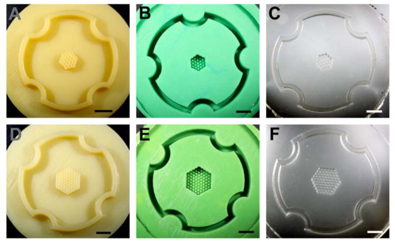
Wax prototypes and replicates of two honeycomb designs. Photographs of the wax prototypes produced by a ThermoJet® rapid prototyping machine from the CAD designs of a two orbital (A) and a four orbital (D) honeycomb. The CAD drawings and resulting wax prototypes were the opposite (negative) of the final hydrogel (positive) which would receive the cells. The longest dimension of the two orbital honeycomb is 0.54 cm and the four orbital honeycomb is 0.94 cm. Positive Reprorubber replicates of the two orbital (B) and the four orbital (E) honeycomb design. Wax prototypes were brittle and easily break, therefore, positive Reprorubber replicas were made to serve as a durable master for the production of numerous PDMS replicas. Negative PDMS replicates of the two orbital (C) and the four orbital (F) honeycomb design. The PDMS replica equals in design the original wax prototype. PDMS replicas can be sterilized in the autoclave and used for casting the agarose micro-molds into which cells are seeded. Scale bars are 0.50 cm.
Those wax prototypes deemed suitable were replicated in a fast curing silicone rubber (positive) which in turn was replicated in polydimethylsiloxane (PDMS)(negative) (Figure 1). One challenge to this next step in the biofabrication process was the fidelity of the silicone rubber replicas and the PDMS replicas, particularly with regards to the small holes and pegs which can trap small air bubbles. A dissecting microscope was used for inspection. Using only acceptable micro-molds, nonadhesive hydrogels were cast from either the PDMS micro-molds (agarose) or the wax prototypes (polyacrylamide). These positive hydrogels were carefully removed, inspected for defects, and then equilibrated in cell culture medium.
To test the ability of these micro-molded hydrogels to direct the self-assembly of a honeycomb structure, they were seeded with mono-dispersed cells. Two different cell types were tested, normal human fibroblasts (NHF), and human granulosa cells (KGN). Each micro-molded hydrogel had a single seeding chamber above a single honeycomb recess. Cells were trypsinized, counted and mono-dispersed cells were carefully pipetted into the seeding chamber. Within minutes, the cells settled to the bottom of the honeycomb recess and were distributed throughout the interconnected contiguous trough that forms the honeycomb (Figure 2). Circular areas devoid of cells were formed by the vertical transparent hydrogel pegs.
Figure 2.
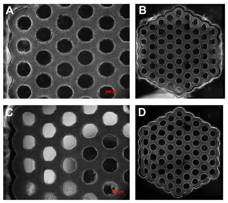
Large multi-cellular honeycombs. NHF (A, B) or KGN (C, D) cells were seeded onto a hydrogel micro-mold where they self-assembled a single four orbital multicellular honeycomb microtissue. Phase contrast images were taken at time zero (cells had settled) (A, C), 3 hours (B) or 9.5 hours (D) later. At time zero, cells are settled throughout the interconnected trough that forms the honeycomb. The circular areas devoid of cells are vertical hydrogel pegs. Self assembly is evident from the overall inward contraction of the honeycomb and the gaps near all pegs. The microtissue conforms to the outer edge of each peg (except the central peg) and on the opposite side there is a gap. Gap width decreases moving inward towards the central peg. Overall, gap widths are larger in the NHF honeycomb indicative of more cell-mediated tension. Note the uniformity of the honeycomb and its lumens, even in areas where the pegs are not perfectly formed. The diameter of the central peg is 600 μm.
Since the mono-dispersed cells are unable to attach to the nonadhesive hydrogel (agarose or polyacrylamide), the small forces of cell- to-cell adhesion caused them to self-assemble a single contiguous microtissue in the shape of a large honeycomb. Time lapse images showed that the directed self-assembly process occurred rapidly (∼12 hours) with significant changes to the entire honeycomb microtissue. Changes were rapid and particularly evident when NHFs were seeded, a cell type we have previously shown to exert significant contractile forces during directed self-assembly [30, 34]. Around the perimeter of the honeycomb, the microtissue contracted inward and conformed to the outer edges of the outer pegs. This was especially evident at those outer pegs located at one of the six corners of the honeycomb. In these locations, the microtissue thinned in the x and y dimensions and was tightly conformed to the outer edges of the peg. At internal locations throughout the honeycomb, the microtissue contracted uniformly inward from all the pegs and the thickness of the microtissue in the x and y dimensions thinned compared to the initial time point. These changes indicated that self-assembly had occurred, that the microtissue increased in thickness in the z dimension and that the entire structure was under cell-mediated tension. Slight defects in mold replication caused some honeycombs to fail in selected regions, but large and stable (5 days) honeycomb microtissues were easily produced in this manner.
To quantify the shape changes that occur during self-assembly, we measured the thickness of the honeycomb at different locations over time (Figure 3). For NHF and KGN honeycombs, we measured microtissue thickness between pegs located within the same orbital and we measured thickness between pegs located in adjacent orbitals. For NHF honeycombs, thickness decreased rapidly to its minimum in one hour and then increased as the microtissue relaxed. A similar pattern was evident within the same orbital as well as between different orbitals. In contrast, the thickness of the KGN honeycomb decreased steadily over the entire time and the decrease began to slow around 15 hours.
Figure 3.
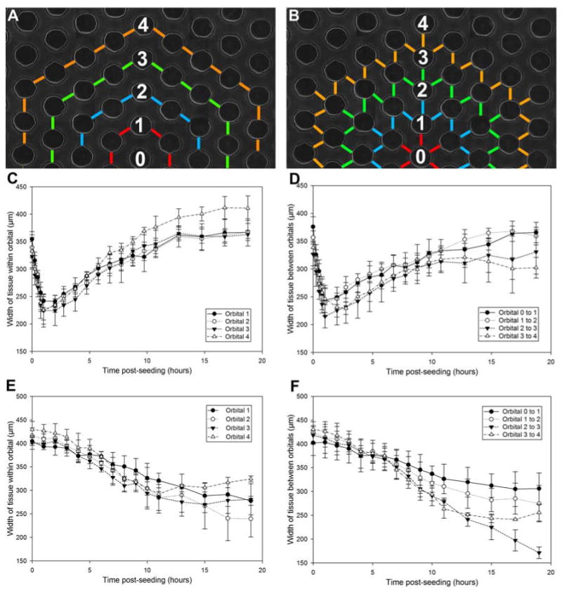
Kinetics of NHF and KGN honeycomb tissue formation. The width of tissue measured between two adjacent pegs within the same orbital (A, C, E) and two pegs between orbitals (B, D, F) changes over time. Hydrogels were seeded with cells and observed for 20 hours. NHFs self-assembled rapidly, causing the tissue width to thin to the minimum within 1 hour, after which point the tissue relaxed around the pegs by expanding (C, D). The maximum distance between pegs is 450 μm. The NHF honeycomb had already undergone some self-assembly and thinning during the ∼20 minutes needed for cell settling and securing the gels in the time lapse microscope. KGNs self-assembled at a significantly slower rate. Tissue width continued to thin over 20 hours (E, F). Error bars represent standard deviation.
To more closely examine the arrangement of cells, honeycombs of NHFs that had self-assembled for 22 hours were fixed and examined using scanning electron microscopy (SEM) (Figure 4). The SEM images showed that the NHFs are densely packed into a complex 3D microtissue with open lumens. In Figures 4A-C, the honeycomb was fixed while it was still in the hydrogel micromold, whereas in Figure 4D, the honeycomb was released from the hydrogel micro-mold prior to fixation. Figure 4A shows that the NHFs are elongated and oriented in specific patterns depending on their location with respect to the lumen. Around the innermost edges of the lumens, the NHFs were thinned and elongated circumferentially to the lumen. This circumferential elongation of cells extends outward from the lumen, but gradually diminished when moving towards the triangular zone located equidistant between nearby lumens (Figure 4B). In the most central region of this zone, cells were less elongated and more triangular in shape. At the corners of the honeycomb (Figure 4C), the microtissue had thinned and the cells were circumferentially elongated with respect to the lumen on both the inner side of the lumen as well as the outer edge of the microtissue. When the honeycomb was fixed after removal from the hydrogel micro-mold (Figure 4D), the lumens narrowed and the cells were less elongated.
Figure 4.
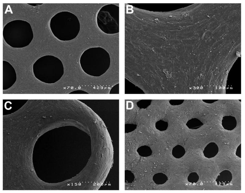
Scanning electron micrographs of multi-cellular honeycombs. SEM images of honeycombs (4 orbital) self-assembled by NHFs (22 hours) that were fixed in the agarose micro-mold (A, B, C) or after release from the agarose micro-mold (D). Specific areas of the honeycomb reveal the differences in honeycomb structure as well as differences in cell morphology. Uniform sized lumens are evident in a central area of the honeycomb (A). NHFs are thin and elongated circumferentially to the lumen and this morphology extends outward from the lumen, but gradually changes to a less elongated more triangular cell shape in the zone located equidistant between nearby lumens (B). At one of the six corners of the honeycomb (C), the microtissue has thinned and circumferentially elongated cells are evident in and around the lumen as well as the outer edge of the microtissue. Removal of the honeycomb causes relaxation and narrowing of the lumens (D). Each SEM image has a scale bar.
To determine if cell viability was maintained in our structures, we formed an even larger honeycomb. It was self-assembled for 24 hours and was stained for live and dead cells (Figure 5). A composite of fluorescent images of this large structure shows that the vast majority of cells in the structure were viable.
Figure 5.
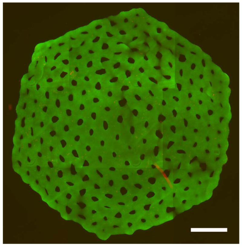
Honeycomb is a viable building unit. The eight orbital honeycomb of NHF (6 × 10⁶ cells) formed in agarose micro-mold was stained for viability with a live/dead assay after 24 hours of culture. Viable cells stained green and dead cells stained red. Shown is the merged red and green fluorescent images stitched together from 9 locations. Scale bar is 1800 μm.
Discussion
In this paper, honeycomb building parts were produced from mono-dispersed cells using directed self-assembly, a process whereby cell-to-cell adhesion in the context of the shape and obstacles of a micro-mold made of a nonadhesive hydrogel drives the formation of a 3D multi-cellular structure that is scaffold-free [30-32]. We tested three honeycomb designs, two cell types, and two hydrogels to demonstrate the versatility and applicability of directed self-assembly to make large scaffold-free multi-cellular honeycombs. Honeycomb micro-molds were produced using polyacrylamide or agarose hydrogels and the method could be scaled up to produce a multicellular honeycomb as large as eight orbitals containing 6 × 10⁶ cells. Our comparison of NHF and KGN cells demonstrates that directed self-assembly is applicable to different cell types and that the kinetics of self-assembly in the honeycomb micro-molds can vary with cell type. NHFs and KGNs both were able to form honeycomb structures within 24 hours with differences in the speed of formation between the cell types. Formation was fastest with the NHFs, consistent with our prior measure of the rate of self-assembly of different cell types [34, 35]. As part of a biofabrication strategy, the time frame of formation of the honeycomb building unit is reasonable and could easily be scaled up by simply increasing the number of honeycomb micro-molds used. We successfully showed that honeycombs as large as four orbitals (∼1 cm corner to corner, 2 × 10⁶ cells) could be produced; however the size could be increased by designing a micro-mold with a honeycomb containing more orbitals. We have had success with a honeycomb containing eight orbitals (∼2 cm, 7 × 10⁶ cells).
After removal from the micro-molds, the honeycomb structures undergo contraction and narrowing of the lumens, with NHF honeycombs contracting faster than KGN honeycombs. The degree of contractility and patency of the lumens depends on the time post-seeding that the honeycomb was released. More mature honeycombs contracted slower, perhaps due to the synthesis of extracellular matrix proteins. In prior publications, we have shown that released honeycombs are stable and that the contraction and narrowing of lumens occurs over a period of days with predictable kinetics, and so could be factored into micro-mold design [31, 32].
We had to overcome several issues for the successful generation of a honeycomb multi-cellular structure. The first issues were related to the resolution of the rapid prototyping machine and the process of replica molding. Wax prototypes produced from our CAD files were not uniformly acceptable and at times had misshapen holes or pegs. Likewise, the replica molding process did not always faithfully replicate the pegs critical to honeycomb formation, so careful inspection was required. Use of misshapen micro-molds led to cellular honeycombs that did not form uniformly or were not adequately constrained by a malformed peg. A second issue we encountered in the formation of honeycomb structures was cell type dependent. The correct cell seeding density was critical and this seeding density could vary with cell type, otherwise the honeycomb would not properly form. Second, cell types differed in the forces of self-assembly and so at times responded to the mold design differently. For example, the SEM images showed that the honeycombs formed by NHFs are under considerable tension. As such, NHF honeycombs were more sensitive to imperfections in the micro-mold as these imperfections could generate point stresses or pegs that did not adequately restrain the honeycomb. Other micro-fabrication technologies with better resolution and optimized micro-mold design would help overcome these limitations.
As a building unit, the honeycomb is significantly larger with far more cells than a spheroid and a toroid. Like the toroid, the honeycomb has numerous open lumens with access to cell culture medium. While the overall x and y dimensions of a honeycomb can be quite large, the cross section of the cellular portion of any part of the honeycomb can be kept small, so as to not exceed the critical diffusion distance needed to maintain cell viability. In addition to size, another advantage over the toroid is that the honeycomb fixes the relative positions of many lumens in the x- y plane, thus providing more premade organization as a building part. Fabrication with honeycomb building parts will still require proper registration in the z plane. In practice, the size of the honeycomb building unit will most likely be limited by the material properties and tensile strength of the building units. Needed are agents that help mature and improve the tensile strength of cellular building units to aid in their mechanical manipulation during biofabrication [36].
As has been shown for spheroids and toroids, it is reasonable to conclude that honeycomb microtissues can fuse with other microtissues (spheroids, honeycombs) as well as adhere to extracellular matrix proteins [2, 5, 6, 8-10, 36, 37]. Such activity is important to any biofabrication strategy and increases the potential complexity (with respect to specific cell positions in 3D) of tissue structures that can be fabricated using a layer-by-layer approach. Likewise, it is possible to make honeycomb building units from two or more different cell types which may self-sort to specific locations in the honeycomb during the directed self-assembly process [30]. And lastly, lumen diameter of the honeycomb building unit can be varied via micromold design in order to optimize diffusive and convective mass transport in the building unit as well as the multi-layered structure into which it would be incorporated. New bioprinting strategies may need to be developed to print honeycomb building units. In summary, the rapid production of the honeycomb building unit, with its multiple rings of high density cells and open lumen spaces, offers interesting new possibilities for biofabrication and may have applications for making large structures such as liver or muscle that have high cell densities and must be perfused during fabrication in order to remain viable.
Acknowledgments
This work was funded, in part, by the NIH R01EB008664-01A1.
References
- 1.Boland T, et al. Cell and organ printing 2: fusion of cell aggregates in three-dimensional gels. Anat Rec A Discov Mol Cell Evol Biol. 2003;272(2):497–502. doi: 10.1002/ar.a.10059. [DOI] [PubMed] [Google Scholar]
- 2.Jakab K, et al. Engineering biological structures of prescribed shape using self-assembling multicellular systems. Proc Natl Acad Sci U S A. 2004;101(9):2864–9. doi: 10.1073/pnas.0400164101. [DOI] [PMC free article] [PubMed] [Google Scholar]
- 3.Jakab K, et al. Tissue engineering by self-assembly and bio-printing of living cells. Biofabrication. 2010;2(2):022001. doi: 10.1088/1758-5082/2/2/022001. [DOI] [PMC free article] [PubMed] [Google Scholar]
- 4.Mironov V, et al. Organ printing: computer-aided jet-based 3D tissue engineering. Trends Biotechnol. 2003;21(4):157–61. doi: 10.1016/S0167-7799(03)00033-7. [DOI] [PubMed] [Google Scholar]
- 5.Mironov V, et al. Organ printing: tissue spheroids as building blocks. Biomaterials. 2009;30(12):2164–74. doi: 10.1016/j.biomaterials.2008.12.084. [DOI] [PMC free article] [PubMed] [Google Scholar]
- 6.Smith CM, et al. Three-dimensional bioassembly tool for generating viable tissue-engineered constructs. Tissue Eng. 2004;10(9-10):1566–76. doi: 10.1089/ten.2004.10.1566. [DOI] [PubMed] [Google Scholar]
- 7.Wilson WC, Jr, Boland T. Cell and organ printing 1: protein and cell printers. Anat Rec A Discov Mol Cell Evol Biol. 2003;272(2):491–6. doi: 10.1002/ar.a.10057. [DOI] [PubMed] [Google Scholar]
- 8.Colton CK. Implantable biohybrid artificial organs. Cell Transplant. 1995;4(4):415–36. doi: 10.1177/096368979500400413. [DOI] [PubMed] [Google Scholar]
- 9.Carmeliet P, Jain RK. Angiogenesis in cancer and other diseases. Nature. 2000;407(6801):249–57. doi: 10.1038/35025220. [DOI] [PubMed] [Google Scholar]
- 10.Ko HC, Milthorpe BK, McFarland CD. Engineering thick tissues--the vascularisation problem. Eur Cell Mater. 2007;14:1–18. doi: 10.22203/ecm.v014a01. discussion 18-9. [DOI] [PubMed] [Google Scholar]
- 11.Borenstein JT, et al. Microfabrication of three-dimensional engineered scaffolds. Tissue Eng. 2007;13(8):1837–44. doi: 10.1089/ten.2006.0156. [DOI] [PubMed] [Google Scholar]
- 12.Fidkowski C, et al. Endothelialized microvasculature based on a biodegradable elastomer. Tissue Eng. 2005;11(1-2):302–9. doi: 10.1089/ten.2005.11.302. [DOI] [PubMed] [Google Scholar]
- 13.McGuigan AP, Leung B, Sefton MV. Fabrication of cell-containing gel modules to assemble modular tissue-engineered constructs [corrected] Nat Protoc. 2006;1(6):2963–9. doi: 10.1038/nprot.2006.443. [DOI] [PubMed] [Google Scholar]
- 14.McGuigan AP, Sefton MV. Vascularized organoid engineered by modular assembly enables blood perfusion. Proc Natl Acad Sci U S A. 2006;103(31):11461–6. doi: 10.1073/pnas.0602740103. [DOI] [PMC free article] [PubMed] [Google Scholar]
- 15.Shimizu T, et al. Polysurgery of cell sheet grafts overcomes diffusion limits to produce thick, vascularized myocardial tissues. FASEB J. 2006;20(6):708–10. doi: 10.1096/fj.05-4715fje. [DOI] [PubMed] [Google Scholar]
- 16.Radisic M, et al. Cardiac tissue engineering using perfusion bioreactor systems. Nat Protoc. 2008;3(4):719–38. doi: 10.1038/nprot.2008.40. [DOI] [PMC free article] [PubMed] [Google Scholar]
- 17.Radisic M, et al. Biomimetic approach to cardiac tissue engineering: oxygen carriers and channeled scaffolds. Tissue Eng. 2006;12(8):2077–91. doi: 10.1089/ten.2006.12.2077. [DOI] [PubMed] [Google Scholar]
- 18.Fleming PA, et al. Fusion of uniluminal vascular spheroids: a model for assembly of blood vessels. Dev Dyn. 2010;239(2):398–406. doi: 10.1002/dvdy.22161. [DOI] [PMC free article] [PubMed] [Google Scholar]
- 19.Gentile C, et al. VEGF-mediated fusion in the generation of uniluminal vascular spheroids. Dev Dyn. 2008;237(10):2918–25. doi: 10.1002/dvdy.21720. [DOI] [PMC free article] [PubMed] [Google Scholar]
- 20.Inamori M, Mizumoto H, Kajiwara T. An approach for formation of vascularized liver tissue by endothelial cell-covered hepatocyte spheroid integration. Tissue Eng Part A. 2009;15(8):2029–37. doi: 10.1089/ten.tea.2008.0403. [DOI] [PubMed] [Google Scholar]
- 21.Moscona A, Moscona H. The dissociation and aggregation of cells from organ rudiments of the early chick embryo. J Anat. 1952;86(3):287–301. [PMC free article] [PubMed] [Google Scholar]
- 22.Foty RA, et al. Surface tensions of embryonic tissues predict their mutual envelopment behavior. Development. 1996;122(5):1611–20. doi: 10.1242/dev.122.5.1611. [DOI] [PubMed] [Google Scholar]
- 23.Kelm JM, Fussenegger M. Microscale tissue engineering using gravity-enforced cell assembly. Trends Biotechnol. 2004;22(4):195–202. doi: 10.1016/j.tibtech.2004.02.002. [DOI] [PubMed] [Google Scholar]
- 24.Fukuda J, Nakazawa K. Orderly arrangement of hepatocyte spheroids on a microfabricated chip. Tissue Eng. 2005;11(7-8):1254–62. doi: 10.1089/ten.2005.11.1254. [DOI] [PubMed] [Google Scholar]
- 25.Fukuda J, Sakai Y, Nakazawa K. Novel hepatocyte culture system developed using microfabrication and collagen/polyethylene glycol microcontact printing. Biomaterials. 2006;27(7):1061–70. doi: 10.1016/j.biomaterials.2005.07.031. [DOI] [PubMed] [Google Scholar]
- 26.Kunz-Schughart LA, et al. Potential of fibroblasts to regulate the formation of three-dimensional vessel-like structures from endothelial cells in vitro. Am J Physiol Cell Physiol. 2006;290(5):C1385–98. doi: 10.1152/ajpcell.00248.2005. [DOI] [PubMed] [Google Scholar]
- 27.Rouwkema J, de Boer J, Van Blitterswijk CA. Endothelial cells assemble into a 3-dimensional prevascular network in a bone tissue engineering construct. Tissue Eng. 2006;12(9):2685–93. doi: 10.1089/ten.2006.12.2685. [DOI] [PubMed] [Google Scholar]
- 28.Kelm JM, et al. Self-assembly of sensory neurons into ganglia-like microtissues. J Biotechnol. 2006;121(1):86–101. doi: 10.1016/j.jbiotec.2005.07.009. [DOI] [PubMed] [Google Scholar]
- 29.Foty RA, Steinberg MS. The differential adhesion hypothesis: a direct evaluation. Dev Biol. 2005;278(1):255–63. doi: 10.1016/j.ydbio.2004.11.012. [DOI] [PubMed] [Google Scholar]
- 30.Dean DM, et al. Rods, tori, and honeycombs: the directed self-assembly of microtissues with prescribed microscale geometries. Faseb J. 2007;21(14):4005–12. doi: 10.1096/fj.07-8710com. [DOI] [PubMed] [Google Scholar]
- 31.Livoti CM, Morgan JR. Self-assembly and tissue fusion of toroid-shaped minimal building units. Tissue Eng Part A. 2010;16(6):2051–61. doi: 10.1089/ten.tea.2009.0607. [DOI] [PMC free article] [PubMed] [Google Scholar]
- 32.Napolitano AP, et al. Dynamics of the self-assembly of complex cellular aggregates on micromolded nonadhesive hydrogels. Tissue Eng. 2007;13(8):2087–94. doi: 10.1089/ten.2006.0190. [DOI] [PubMed] [Google Scholar]
- 33.Nishi Y, et al. Establishment and characterization of a steroidogenic human granulosa-like tumor cell line, KGN, that expresses functional follicle-stimulating hormone receptor. Endocrinology. 2001;142(1):437–45. doi: 10.1210/endo.142.1.7862. [DOI] [PubMed] [Google Scholar]
- 34.Dean DM, Morgan JR. Cytoskeletal-mediated tension modulates the directed self-assembly of microtissues. Tissue Eng Part A. 2008;14(12):1989–97. doi: 10.1089/ten.tea.2007.0320. [DOI] [PubMed] [Google Scholar]
- 35.Youssef J, et al. Quantification of the forces driving self-assembly of three-dimensional microtissues. Proc Natl Acad Sci U S A. 2011 doi: 10.1073/pnas.1102559108. [DOI] [PMC free article] [PubMed] [Google Scholar]
- 36.Hajdu Z, et al. Tissue spheroid fusion-based in vitro screening assays for analysis of tissue maturation. J Tissue Eng Regen Med. 2010;4(8):659–64. doi: 10.1002/term.291. [DOI] [PMC free article] [PubMed] [Google Scholar]
- 37.Rago AP, Dean DM, Morgan JR. Controlling cell position in complex heterotypic 3D microtissues by tissue fusion. Biotechnol Bioeng. 2009;102(4):1231–41. doi: 10.1002/bit.22162. [DOI] [PubMed] [Google Scholar]