

Abstract
Electrochemical detection combined with nanostructured sensor surfaces offers potentially low-cost, high-throughput solutions for detection of clinically significant proteins. Inkjet printing offers an inexpensive non-contact fabrication method for microelectronics that is easily adapted for incorporating into protein immunosensor devices. Herein we report the first direct fabrication of inkjet-printed gold nanoparticle arrays, and apply them to electrochemical detection of the cancer biomarker interleukin-6 (IL-6) in serum. The gold nanoparticle ink was printed on a flexible, heat resistant polyimide Kapton substrate and subsequently sintered to create eight-electrode arrays costing <0.2 euro per array. The inkjet-printed working electrodes had reproducible surface areas with RSD <3%. Capture antibodies for IL-6 were linked onto the eight-electrode array, and used in sandwich immunoassays. A biotinylated secondary antibody with 16-18 horseradish peroxidase labels was used, and detection was achieved by hydroquinone-mediated amperometry. The arrays provided a clinically relevant detection limit of 20 pg mL−1 in calf serum, sensitivity of 11.4 nA pg−1 cm−2, and a linear dynamic range of 20–400 pg mL−1.
1. Introduction
Electrochemical detection combined with nanoparticle amplification offers potentially low-cost, high-throughput solutions for detection of clinically significant proteins that have yet to be fully realized. Amperometric sensors, field effect transistors, and impedance methods are among the approaches being explored.1–5 The sensitivity of an electrochemical sensor can be improved by using nanostructured electrodes, such as those based on carbon nanotubes6,7 or gold nanoparticles.8,9 In the electrochemical detection of proteins on these high specific area electrode surfaces by immunoassay protocols, appropriate functional groups on the nanoparticle facilitate high concentrations of chemically linked capture antibodies.10 In this approach, antibodies on the electrode capture analyte proteins from the sample, then the surface can be treated with an enzyme-labeled secondary antibody, and the enzyme label is detected electrochemically.5
It is important to detect multiple proteins for accurate medical diagnostic predictions.5 Electrochemical detection formats can measure multiple proteins on a multi-electrode microelectronic chip11–15 and can be coupled with bioconjugated enzyme-antibody particles with large numbers of enzyme labels for further amplification as required for the target protein.9 Microelectronic arrays for this purpose should have high surface area to enhance sensitivity, be easy to produce, and be inexpensive enough for single use application to avoid contamination and regeneration of the sensing surface. Electrochemical protein arrays have been developed by Wilson and Nie for up to seven tumor biomarkers using chips based on the porous iridium oxide electrode.11,12 Microelectronic arrays for detecting salivary biomarkers such as IL-8 and thioredoxin have been developed by Wong et al.13,14 We recently used a simple electrochemical immunoarrays featuring single-walled carbon nanotube forest electrodes to simultaneously measure four prostate cancer biomarkers in cancer patient serum.15 Ultimately, electrochemical protein microarrays have good prospects for accurate, inexpensive, ultra-sensitive measurement of small numbers of proteins for disease diagnosis.
Fabrication of electrochemical arrays can be accomplished in several ways. The standard method for gold array fabrication is chemical vapor deposition (CVD) coupled with photolithography.16 This powerful technique allows for well-defined electrode fabrication and insulation. While very few methods can compete with CVD in terms of precision, it requires multiple processing steps including application of photoresist, exposure to mask, etching and deposition of adhesion and electrode materials. The large number of steps increases the cost per electrode and limits the disposable use of these arrays. Inkjet-printed electronics are an attractive option for the fabrication of arrays due to their relative speed of fabrication, ability to produce three-dimensional structures, and the non-contact nature of the process.17 Inkjet-printing has the potential for the production of thin-film transistors, radio frequency identification tags, and solar cells. Inkjet deposition of mask materials such as alkyl thiols on gold followed by etching away unwanted conductive materials has been used for electrochemical array production.18 Nanoparticle inks have been directly printed as conductive tracks,19,20 but to our knowledge not for individually addressable electrodes in arrays. Electrical conductivity of the printed features is achieved by sintering nanoparticles such as silver, gold, and copper after printing via high temperature, laser pulsing, or microwave irradiation.16,21–24
Protein biomarkers are up-regulated and down-regulated in blood serum due to disease.25 Determination of concentrations of these proteins in serum is an emerging tool for detecting and monitoring cancers.5,26,27 Reliance on the concentration of a single biomarker such as prostate specific antigen (PSA) can result in significant numbers of false positives and false negatives.28,29 However, measurement of panels of protein biomarkers increases the statistical accuracy of prediction and can overcome problems associated with single biomarkers.5
Interleukin-6 (IL-6) is a promising early indicator of several serious medical conditions.30 Elevated IL-6 serum levels are associated with development and/or progression of breast, cervical, oral, and colorectal cancers.31–34 IL-6 has also been reported as an early marker for inflammation and post-operative infections.35,36 Additionally, recent studies suggest that traumatic brain injury patients with elevated serum concentrations of IL-6 are more likely to develop life-threatening symptoms.37 Concentrations of IL-6 in healthy adults are less than 6 pg mL−1, but elevate to above 80 pg mL−1 in patients with cancer or abnormal inflammation.31–34 The low concentrations of IL-6 in serum present a challenging target for immunoassays, and we recently reported nanostructured single-electrode immunosensors featuring carbon nanotube forests or 5 nm AuNP layers for detection of IL-6 in the pg mL−1 range and below.38,39 Immunosensing of IL-6 was chosen in the present work as our proof-of-concept application target. In this paper, we report the first direct inkjet fabrication and characterization of electrochemical arrays using 4 nm gold nanoparticles and poly(amic acid) inks on heat-resistant Kapton plastic, and subsequent application to an immunosensor array demonstrated by the detection of IL-6 in serum in the pg mL−1 range.
2. Experimental
2.1 Chemicals and materials
A Kapton FPC film 127 μm thick was purchased from American Durafilm. These large polymer sheets were washed with water and ethanol prior to use. Lyophilized 99% bovine serum albumin (BSA), sterile-filtered bovine calf serum, gold(III) chloride trihydrate, 1-dodecanethiol, tetraoctylammonium bromide, sodium borohydride, N-hydroxy-sulfosuccinimide, 1-ethyl-3-[3-dimethylaminopropyl]carbodiimide hydrochloride, poly(amic acid) and Tween-20 were purchased from Sigma-Aldrich. Capture anti-human mouse antibodies, recombinant human interleukin-6, biotinylated secondary goat anti-human antibodies, and streptavidin–horseradish peroxidase (HRP) conjugates were purchased from R&D systems as a DuoSet ELISA kit (DY206).
2.2 Instrumentation
All electrochemical measurements were made using a CHI 1040A eight-channel potentiostat simultaneously for all eight electrodes at room temperature. All potentials are reported vs. a common saturated calomel reference (SCE) electrode, and cells employed a common platinum auxiliary electrode.
A Dimatix Materials Printer (ModelDMP-2800, FUJIFILM Dimatix, Inc. Santa Clara, CA) was used for inkjet printing. Dimatix 10 pL, liquid crystal polymer printer cartridges were used for all printed inks (Model DMCLCP-11610). Printing patterns were made utilizing the Dimatix materials printer software. All printing patterns were developed using Microsoft Paint (Microsoft Inc. Redmond, WA) and imported using the Dimatix Materials Printer with Dimatix Printer Controller software. Each pattern was printed with 15 μm spacing between drops and using a custom printing waveform and each pattern was printed using a single jet for facile detection of clogs.
Atomic force microscopy (AFM) of gold nanoparticle arrays was done using a Digital Instruments Nanoscope IV scanning probe microscope, in tapping mode with symmetric tip high-resolution TappingMode AFM probes (Veeco Metrology Inc., Model MPP-11100).
2.3 Gold nanoparticle synthesis and ink formulation
Dodecane thiol-protected gold nanoparticles were synthesized as previously reported by Hostetler et al.40 Briefly, 1.5 g of tetraoctylammonium bromide was placed in a round-bottom flask containing 80 mL toluene and 20 mL water and stirred vigorously. 432 mg of gold(III) chloride trihydrate was added to the solution and mixed for 5 min. The organic phase was separated and 43.8 μL of 1-dodecane thiol was added and stirred for 10 min. 380 mg sodium borohydride was dissolved in 25 mL of water and quickly added to the vigorously stirring gold(III) chloride solution. The solution immediately turned dark in color and was then stirred for 3 h. Next, the organic phase was washed with several aliquots of water and toluene was removed by rotary evaporation under reduced pressure at 50 °C. The gold nanoparticles were dispersed in ethanol and filtered, after which they were washed with several aliquots of water followed by ethanol. The washed gold nanoparticles were covered and allowed to dry in air overnight prior to further use. Isolated particles on mica analyzed by AFM had an average diameter of 4.3 ± 0.8 nm (n = 100).
The gold nanoparticle ink was prepared by dissolving dodecane thiol-protected gold nanoparticles in toluene to a concentration of 100 mg mL−1. The gold nanoparticle solution was filtered prior to use with a 0.2 μm cutoff PTFE filter. 1.5 mL of the gold nanoparticle ink was injected into a liquid crystal Dimatix printer cartridge immediately prior to use.
Poly(amic acid) ink was prepared by diluting the 10% (m/m) poly(amic acid) solution in highly pure N-methyl-2-pyrrolidone (NMP) to 1% (m/m). The solution was gently shaken to mix and the poly(amic acid) was injected into a liquid crystal Dimatix printer cartridge immediately prior to use.
2.4 Array fabrication
For printing, clean 22 × 28 cm polyimide films were placed in the Dimatix printer and heated to 35 °C and secured using the platen vacuum. The gold nanoparticle ink cartridges were placed in the Dimatix printer and visually checked using the high-speed drop watcher camera to ensure consistent ink droplet formation. The printer was aligned with the substrate. The pattern file was set to allow for printing multiple arrays in a single printing, with varying spacing between arrays. The gold nanoparticle ink was then printed onto the polyimide film. Following deposition of the gold nanoparticle ink onto the Kapton substrate, the arrays were heated to 200 °C for 3 min or until the films lightened slightly in color. The films were then briefly rinsed with water and returned to the printer for application of poly(amic acid) ink. The poly(amic acid) ink was placed in the printer and the arrays were aligned using the fiducial camera. Five layers of poly(amic acid) ink were printed over the array leads, leaving the working gold nanoparticle electrodes and electrical contacts uncovered. Following application of the poly(amic acid) layer, arrays were heated to 200 °C for 30 min to allow for imidization of the poly-(amic acid) solution to provide an insulating layer of polyimide on the leads. The arrays were separated and washed with water prior to immunosensor formation. Surface area and reproducibility of the electrochemical arrays were estimated by cyclic voltammetry (CV) for a solution of 4 mM potassium ferrocyanide in 100 mM KCl. Scan rates were varied from 100 to 10 mV s−1.
2.5 Immunosensor fabrication and assay protocols
Steps in immunosensor fabrication are as follows:
The arrays were placed in 0.18 Msulfuric acid, connected to a potentiostat, and cycled from −0.2 V to +1.5 V vs. SCE to clean the electrodes. The arrays were then washed in water and ethanol and placed in 4 mM 3-mercaptopropionic acid (MPA) in ethanol for 12 h to form a self-assembled monolayer (SAM). Then, electrodes were washed successively in ethanol, PBS buffer pH 7.0, and deionized water.
The carboxylic acid end groups of the SAM were activated for antibody binding by placing 50 μL of freshly prepared 400 mM EDC and 100 mM NHSS over all eight electrodes for 10 min.9 Electrodes were rinsed with water to remove excess solution and 50 μL of 100 μg mL−1 primary antibody solution was placed over all eight electrodes and allowed to react for 3 h at room temperature.
Following primary antibody application the electrodes were washed by placing each array in ~5 mL of PBS buffer with 0.05% Tween-20 surfactant. Then, arrays were gently shaken for 1.5 min and the process was repeated once with fresh PBS Tween 20 buffer and twice with PBS buffer. The electrodes were shaken to remove excess wash buffer.
To block nonspecific binding (NSB), 50 μL of 2%BSA in PBS Tween-20 was deposited to cover all eight electrodes and incubated at room temperature for 1 h.9 Then, electrodes were washed using the protocol described above (step 3).
Following the NSB blocking, 50 μL of calf serum containing IL-6 standards was deposited on each eight-electrode array, which was incubated at room temperature for 80 min, and electrodes were washed as above (step 3).
50 μL of 10 μg mL−1 anti-human IL-6 biotin-labeled secondary antibody solution was placed on the electrodes following sample incubation and allowed to stand 75 min. The electrodes were washed as above (step 3).
Following the secondary antibody step, 50 μL of streptavidin–HRP solution was placed on the arrays covering all eight electrodes for 30 min. This approach provided 16-18 HRP labels per analyte.38 Electrodes were washed as above (step 3), covered, and stored at 4 °C while waiting for electrochemical analysis.
For amperometric detection, hydroquinone was added to a final concentration of 1.0 mM in 20 mL of PBS buffer in an electrochemical cell with a saturated calomel reference electrode and a platinum counter electrode. The electrochemical arrays were connected to the potentiostat using an eight-probe 3 M clip, and held in place by a lab-built polyvinylchloride holder. The cell was purged for 3 min prior to use with highly purified argon and a blanket of argon was maintained during electrochemical measurements. The solution was stirred with a magnetic stir bar at ~100 rpm. Electrodes were held at −0.3 V vs. SCE and the current was allowed to equilibrate for ~100 s. Upon stabilization, hydrogen peroxide was injected to give a final concentration of 0.4 mM, and the current was sampled every 0.1 s.
3. Results
3.1 Array fabrication
Ink made from dodecane thiol-protected gold nanoparticles (AuNPs) dissolved in toluene was adjusted in concentration to allow reproducible formation of conductive lines in a single printing and to avoid clogging of the inkjets. AuNPs at 100 mg mL−1 in toluene produced stable inks that could print using the Dimatix printer for twenty-four hours without clogging the inkjets. However, storage of the ink within the cartridge over a period of a week was problematic due to slow evaporation of toluene and aggregation of the AuNPs.
1% polyamic acid by weight in N-methyl-2-pyrrolidone (NMP) having a kinematic viscosity of 4.28 ± 0.03 cP as measured by a capillary viscometer allowed for facile inkjet printing of an insulating film. The poly(amic acid) solution printed well using the custom waveform and printed continuously for 24 h without clogging. Furthermore, the poly(amic acid) cartridges were stable for a week when stored in a closed container and printed well following one week of storage.
The custom waveform is shown in Fig. 1. This waveform maximum voltage for both the jetting and non-jetting waveforms was adjusted prior to printing the patterns. Adjustments were made while observing the individual inkjet with the built-in drop watch camera of the Dimatix printer. Both inks printed reproducibly using this waveform with voltages applied in the 20–30 V range for the jetting waveform and 3–5 V for the non-jetting waveform.
Fig. 1.
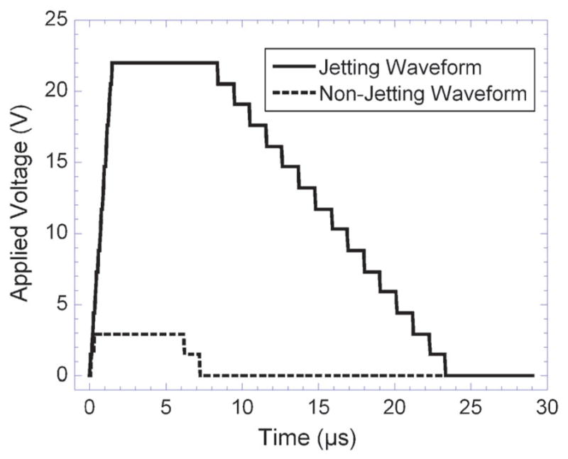
Jetting and non-jetting waveforms used for printing both gold nanoparticles and poly(amic acid) inks (shown at 22 V). The two waveforms were sequentially applied based on the pattern to be printed. The non-jetting waveform prevents film formation at the ink–air interface while the jetting waveform causes the application of a single drop of ink.
Using the custom waveform, the gold nanoparticle ink was printed in an eight-electrode array pattern (Scheme 1). The spacing between drops was set at 15 μm between each pixel, this spacing provides overlap as each drop spreads to an approximate 40 μm diameter. The pattern was set to print a square working electrode of dimensions 465 × 465 μm. For each eight-electrode array, approximately 600 μg of gold was printed. When printed, the gold nanoparticle ink spread as expected, with the effect being most noticeable on the bottom of the electrode, which was the last portion of the array printed (Fig. 2). After spreading, the two-dimensional surface area of the arrays resulted in a geometric area of 0.299 ± 0.015 mm2. Following gold nanoparticle printing, the arrays were sintered for ~3 min at 200 °C. The arrays slightly lightened in color marking loss of the dodecane thiol layer and formation of percolation paths through the gold nanoparticle network.24 After heating, the dry resistance of gold arrays from contact to working electrode was 20–25 ohms.
Scheme 1.

Fabrication of AuNP arrays: (A) inkjet printing of the AuNP ink onto the polyimide substrate; (B) inkjet printing the poly(amic acid) ink to insulate the electrode leads; (C) building the immunoassay for electrochemical detection of human IL-6; (D) the AuNP pattern (black) shown overlaid with the poly(amic acid) printed pattern (orange).
Fig. 2.

Photographs of the array: (A) printed AuNP array with the protective polyimide insulating film; (B) picture taken using the Dimatix printer’s fiducial camera showing a typical single AuNP working electrode.
Poly(amic acid) ink was printed over the sintered gold nanoparticle arrays to insulate the leads. Poly(amic acid), when heated for 30 min at 200 °C, dehydrates to form polyimide (Scheme 2), which adheres very strongly to the Kapton polyimide substrate.41 Imidization of the poly(amic acid) essentially seals the gold leads between the polyimide substrate and the newly formed polyimide coating. Due to the low concentration of poly(amic acid) in the poly(amic acid) ink, a total of five layers of ink were required in the pattern shown in Scheme 1. Aligning the gold nanoparticle arrays for the application of the poly(amic acid) ink was difficult due to its low visibility. A test pattern consisting of several lines was printed to provide visualization and allow adjustment of the printing origin. Once aligned, five layers of the poly(amic acid) ink were printed to ensure that the narrow leads were completely insulated. The imidization process then formed a protective, insulating polyimide layer over the leads.
Scheme 2.

Poly(amic acid) dehydration to give the corresponding polyimide.
The working electrodes of the gold nanoparticle arrays were clearly rough surfaces with well-defined borders as seen in Fig. 2. Tapping-mode AFM (Fig. 3) images revealed a rough surface featuring larger hills and valleys superimposed on a smaller close packed particle landscape consistent with well-defined individual AuNPs in a sintered network. The mean surface roughness was 21 ± 5 nm for the sintered gold nanoparticle surface, confirming a rough nanostructured electrode surface suitable for fabrication of an immunosensor.
Fig. 3.
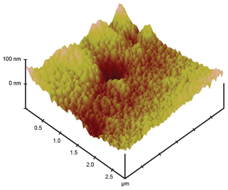
Tapping mode AFM of one of eight sintered working electrodes in an inkjet-printed gold nanoparticle array.
One of the major advantages of inkjet-printed arrays is the feasibility of large scale production using industrial inkjet printers. In this study, multiple arrays were printed in each printing run. An example is shown in Fig. 4 where 56 gold nanoparticle arrays were produced in a single printing. This was scaled up to produce up to 80 arrays in a single printing (not shown).
Fig. 4.

Kapton substrate after printing 56 eight-electrode AuNP arrays in a single run (shown within the Dimatix Materials Printer).
Following cleaning, the eight electrodes were scanned simultaneously by cyclic voltammetry in 1 mM potassium ferricyanide solution and 100 mM potassium chloride (Fig. 5). The electrochemical surface area of the arrays was determined, using the oxidation peak current, the Randles-Sevcik equation and the known diffusion coefficient of ferrocyanide to be 0.35 ± 0.01 mm2.42 This area is 116% of the geometric surface area estimated by analysis of fiducial camera images. The working electrodes showed good reproducibility in electrochemical surface area with a relative standard deviation from electrode to electrode of <3%, which is directly relevant to applications of the array.
Fig. 5.
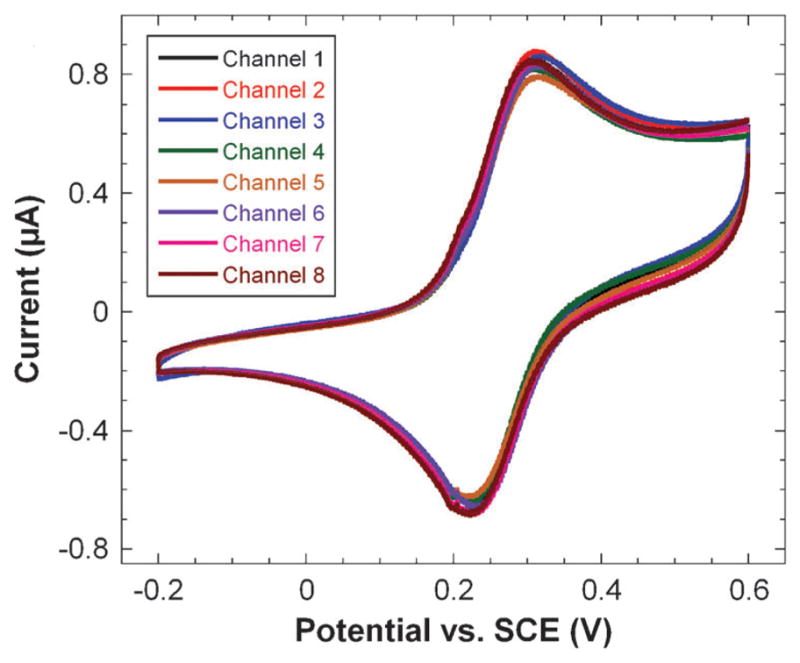
Simultaneous cyclic voltammograms of all eight array electrodes in 1 mM potassium ferricyanide and 100 mM potassium chloride at a scan rate of 100 mV s−1.
3.2 Immunosensor application
Immunosensors for IL-6 were built on the arrays by covalently binding a primary anti-human IL-6 antibody to a MPA self-assembled monolayer on the gold surface. The amount of IL-6 containing serum used per array was 6.25 μL per electrode, which covered the working electrodes completely. For each array, a single IL-6 concentration in calf serum was used. After binding of IL-6 and HRP-labeled secondary antibody to the arrays, the eight electrode array was placed in an electrochemical cell containing pH 7 buffer and 1 mM hydroquinone as mediator. The solution was stirred to achieve rapid mass transport and hydrogen peroxide was injected into the cell to producing a step in the current by catalytic reduction of the peroxide by the HRP enzyme labels. Stirring the solution induced a high frequency periodic oscillation that correlated with the stir speed. The current sampled at 0.1 s intervals was plotted as a moving three-second average of the current vs. time. Representative single electrode three-second averaged amperograms are shown in Fig. 6 for different concentrations of IL-6 in undiluted calf serum.
Fig. 6.

Representative amperograms of immunosensors for IL-6 in undiluted calf serum represented as three-second moving averages of the raw reduction current sampled every 0.1 s for the gold nanoparticle array in pH 7 buffer containing 1 mM hydroquinone. Each plot shows the current increase of a single electrode upon injection of hydrogen peroxide on individual arrays. The average current for each electrode was measured upon reaching a steady state and the current increases were averaged for each concentration to generate the calibration curve (Fig. 7). This calibration curve shows that the current increased linearly from 6 to 394 pg mL−1. Immunoarray sensitivity from the slope of the calibration curve was 11.4 nA pg−1 cm−2 for IL-6 with a detection limit of 20 pg mL−1. The detection limit was estimated from the calibration curve as 3 standard deviations larger than the 0 pg mL−1 response. The standard deviations of the current increased at the higher concentrations as the immunosensors approached surface saturation.
4. Discussion
Inkjet-printed electronics hold enormous potential for the fabrication of low cost sensors and devices. A single array as described here costs less than 0.2 euro in materials to produce. The non-contact fabrication of inkjet-printed arrays allowed for the simultaneous production of a large number of devices that were highly reproducible, conductive and easily adapted to fabrication of an immunosensor. This could easily be scaled up to print arrays in larger numbers at lower cost with an industrial-sized ink-jet printer. This ease of modification of the inkjet pattern is a major advantage of the printing technique. Patterns can be changed in a matter of minutes for prototype development. This advantage is clear when inkjet printing is compared to either screen-printing or chemical vapor deposition. While changes in screen-printed or CVD processes require the development of a new mask or screen, inkjetprinted patterns can be simply modified using conventional artwork programs.
Thiol-protected AuNPs used in this work allowed development of highly stable ink formations that could be reproducibly printed on heat and chemically resistant Kapton plastic and sintered. These sintered gold nanoparticle networks had low resistance across the film and a nanostructured surface. The use of toluene as the solvent for the gold nanoparticles required a liquid crystal polymer printer cartridge but for industrial applications the inkjet reservoir could no doubt be designed to handle the solvent. Printing the poly(amic acid) insulating layer provided a well defined, reproducible surface area with <3% variation from electrode to electrode. Following the imidization of the poly(amic acid) solution the arrays were well protected with a stable and flexible coating.
The inkjet-printed gold nanoparticle arrays provided an immunosensor for multiple determinations of human IL-6 in serum with a detection limit and linear range in the clinically significant range for some cancers and for head trauma patients. These promising sensors are easily fabricated at relatively low cost, and could be mass-produced with commercial inkjetters. The sensors produced can be easily modified to detect a wide range of clinically significant species and are cheap enough to be disposable. Future work will explore printing both the self-assembled monolayer and primary antibody to each individual electrode to create an immunosensor that can be machine produced by drop-on-demand technologies.
In summary, results above demonstrate an elegant, cheap, and simple technique for fabricating AuNP arrays by direct ink-jet printing, and adapted them to very sensitive immunosensing of IL-6. The detection limit of 20 pg mL−1 for IL-6 is similar to those for previously reported nanostructured amperometric immunosensors for IL-6 when the same 16-18 HRP label strategy was used.38,39 Furthermore, the ability to obtain this low a detection limit and good sensitivity in calf serum, which is a good mimic for human serum,43 suggests an excellent selectivity in media that contain thousands of competing proteins with many at higher concentrations than the analyte.3–5 These printed AuNP arrays are readily adaptable to amplification methods previously developed, including the use of multilabeled-nanoparticle-secondary antibodies.5,9,39,43,44 We are currently interfacing these eight-electrode arrays to microfluidic devices to provide better control over mass transport of mediator and peroxide to the electrode surface to eliminate current oscillations caused by stirring and improve signal/noise. Because the ink-jetted pattern is easily modified, fast prototyping of patterns for use in microfluidic devices can be achieved.
Fig. 7.

Gold nanoparticle array immunosensor calibration curve for IL-6 in undiluted calf serum (n = 7).
Acknowledgments
This research was supported financially by PHS grant ES013557 from NIEHS/NIH.
References
- 1.Wang J. Analyst. 2005;130:421–426. doi: 10.1039/b414248a. [DOI] [PubMed] [Google Scholar]
- 2.Wang J. Biosens Bioelectron. 2006;21:1887–1892. doi: 10.1016/j.bios.2005.10.027. [DOI] [PubMed] [Google Scholar]
- 3.Tkac J, Davis JJ. In: Engineering the Bioelectronic Interface. Davis JJ, editor. Royal Soc. Chem; UK: 2009. pp. 193–224. [Google Scholar]
- 4.Giljohan DA, Mirkin CA. Nature. 2009;462:461–464. doi: 10.1038/nature08605. [DOI] [PMC free article] [PubMed] [Google Scholar]
- 5.Rusling JF, Kumar CV, Gutkind JS, Patel V. Analyst. 2010;135:2496–2511. doi: 10.1039/c0an00204f. [DOI] [PMC free article] [PubMed] [Google Scholar]
- 6.Kim SN, Rusling JF, Papadimitrakopoulos F. Adv Mater. 2007;19:3214–3228. doi: 10.1002/adma.200700665. [DOI] [PMC free article] [PubMed] [Google Scholar]
- 7.Rusling JF, Yu X, Munge BS, Kim SN, Papadimitrakopoulos F. In: Engineering the Bioelectronic Interface. Davis J, editor. Royal Soc. Chem; UK: 2009. pp. 94–118. [Google Scholar]
- 8.Murray RW. Chem Rev. 2008;108:2688–2720. doi: 10.1021/cr068077e. [DOI] [PubMed] [Google Scholar]
- 9.Mani V, Chikkaveeraiah BV, Patel V, Gutkind JS, Rusling JF. ACS Nano. 2009;3:585–594. doi: 10.1021/nn800863w. [DOI] [PMC free article] [PubMed] [Google Scholar]
- 10.Malhotra R, Papadimitrakopoulos F, Rusling JF. Langmuir. 2010;26:15050–15056. doi: 10.1021/la102306z. [DOI] [PMC free article] [PubMed] [Google Scholar]
- 11.Wilson MS, Nie W. Anal Chem. 2006;78:2507–2513. doi: 10.1021/ac0518452. [DOI] [PubMed] [Google Scholar]
- 12.Wilson MS, Nie W. Anal Chem. 2006;78:6476–6483. doi: 10.1021/ac060843u. [DOI] [PubMed] [Google Scholar]
- 13.Wei F, Liao W, Xu Z, Yang Y, Wong DT, Ho CM. Small. 2009;5:1784–1790. doi: 10.1002/smll.200900369. [DOI] [PMC free article] [PubMed] [Google Scholar]
- 14.Wei F, Patel P, Liao W, Chaudhry K, Zhang L, Arellano-Garcia M, Hu S, Elashoff D, Zhou H, Shukla S, Shah F, Ho CM, Wong DT. Clin Cancer Res. 2009;15:4446–4452. doi: 10.1158/1078-0432.CCR-09-0050. [DOI] [PMC free article] [PubMed] [Google Scholar]
- 15.Chikkaveeriah BV, Bhirde A, Malhotra R, Patel V, Gutkind JS, Rusling JF. Anal Chem. 2009;81:9129–9134. doi: 10.1021/ac9018022. [DOI] [PMC free article] [PubMed] [Google Scholar]
- 16.Fourkas JT. J Phys Chem Lett. 2010;8:1221–1227. [Google Scholar]
- 17.Calvert P. Chem Mater. 2001;13:3299–3305. [Google Scholar]
- 18.Li Y, Li PCH, Parameswaran M, Yu H. Anal Chem. 2008;80:8814–8821. doi: 10.1021/ac801420h. [DOI] [PubMed] [Google Scholar]
- 19.Huang D, Liao F, Molesa S, Redinger D, Subramanian V. J Electrochem Soc. 2003;150:G412–G417. [Google Scholar]
- 20.Bieri NR, Chung J, Poulikakos D, Grigoropoulos CP. Appl Phys A: Mater Sci Process. 2005;80:1485–1495. [Google Scholar]
- 21.Van Osch THJ, Perelaer J, de Latt AWM, Schubert US. Adv Mater. 2008;20:343–345. [Google Scholar]
- 22.Lee KJ, Jun BH, Kim TH, Joung J. Nanotechnology. 2006;17:2424–2428. [Google Scholar]
- 23.Ko SH, Pan H, Grigoropoulos CP, Luscombe CK, Fréchet JMJ, Poulikakos D. Appl Phys Lett. 2007;90:141103. [Google Scholar]
- 24.Sivaramakrishnan S, Chia PJ, Yeo YC, Chua LL, Ho PK. Nat Mater. 2006;6:149–155. doi: 10.1038/nmat1806. [DOI] [PubMed] [Google Scholar]
- 25.Xiao Z, Prieto D, Conrads TP, Veenstra TD, Issaq HJ. Mol Cell Endocrinol. 2005;230:95–106. doi: 10.1016/j.mce.2004.10.010. [DOI] [PubMed] [Google Scholar]
- 26.Hanash SM, Pitteri SJ, Faca VM. Nature. 2008;452:571–579. doi: 10.1038/nature06916. [DOI] [PubMed] [Google Scholar]
- 27.Kulasingam V, Diamandis EP. Nat Clin Pract Oncol. 2008;5:588–599. doi: 10.1038/ncponc1187. [DOI] [PubMed] [Google Scholar]
- 28.Schröder FH, Hugosson J, Roobol MJ, Tammela TLJ, Ciatto S, Nelen V, Kwiatkowski M, Louis JD, Recker F, Berenguer A, Määttänen L, Bangma CH, Aus G, Villers A, Rebillard X, van der Kwast T, Blijenber BG, Moss SM, de Koning HJ, Auvinen A. N Engl J Med. 2009;360:1320–1328. doi: 10.1056/NEJMoa0810084. [DOI] [PubMed] [Google Scholar]
- 29.Thompson IM, Pauler DK, Goodman PJ, Tangen CM, Lucia MS, Parnes HL, Minasian LM, Ford LG, Lippman SM, Crawford ED, Crowley JJ, Coltman CA. N Engl J Med. 2004;350:2239–2246. doi: 10.1056/NEJMoa031918. [DOI] [PubMed] [Google Scholar]
- 30.Kishimoto T, Akira S, Narazaki M, Taga T. Blood. 2005;86:1243–1254. [PubMed] [Google Scholar]
- 31.Zhang GJ, Adachi I. Anticancer Res. 1999;19:1427–1432. [PubMed] [Google Scholar]
- 32.Wei LH, Kuo ML, Chen CA, Chou CH, Cheng WF, Chang MC, Su JL, Hsieh CY. Oncogene. 2001;20:5799–5809. doi: 10.1038/sj.onc.1204733. [DOI] [PubMed] [Google Scholar]
- 33.Chung YC, Chaen YL, Hsu CP. Anticancer Res. 2006;26:3905–3911. [PubMed] [Google Scholar]
- 34.Riedel F, Zaiss I, Herzog D, Gotte K, Naim R, Horman K. Anticancer Res. 2005;25:2761–2766. [PubMed] [Google Scholar]
- 35.Kragsbjerg P, Hoimberg H, Vikerfors T. Eur J Surg. 1995;161:17–22. [PubMed] [Google Scholar]
- 36.Di Cesare PE, Chang E, Preston CF, Liu CL. J Bone Jt Surg. 2005;87:1921–1927. doi: 10.2106/JBJS.D.01803. [DOI] [PubMed] [Google Scholar]
- 37.Hergenroeder GW, Moore AN, McCoy JP, Samsel L, Ward NH, Clifton GL, Dash PK. J Neuroinflammation. 2010;7:19–19. doi: 10.1186/1742-2094-7-19. [DOI] [PMC free article] [PubMed] [Google Scholar]
- 38.Munge BS, Krause CE, Malhotra R, Patel V, Gutkind JS, Rusling JF. Electrochem Commun. 2009;11:1009–1012. doi: 10.1016/j.elecom.2009.02.044. [DOI] [PMC free article] [PubMed] [Google Scholar]
- 39.Malhotra R, Patel V, Vaqué JP, Gutkind JS, Rusling JF. Anal Chem. 2010;82:3118–3123. doi: 10.1021/ac902802b. [DOI] [PMC free article] [PubMed] [Google Scholar]
- 40.Hostetler MJ, Wingate JE, Zhong CJ, Harris JE, Vachet RE, Clark MR, Londono JD, Green SJ, Stokes JJ, Wignall GD, Glish GL, Porter MD, Evans ND, Murray RW. Langmuir. 1998;14:17–30. [Google Scholar]
- 41.Oba M. J Polym Sci Part A: Polym Chem. 1996;34:651–658. [Google Scholar]
- 42.Bard AJ, Faulkner LR. Electrochemical Methods Fundamentals and Applications. 2. John Wiley & Sons; New York: 2001. [Google Scholar]
- 43.Yu X, Munge B, Patel V, Jensen G, Bhirde A, Gong J, Kim S, Gillespie J, Gutkind S, Papadimitrakopolous F, Rusling JF. J Am Chem Soc. 2006;128:11199–11205. doi: 10.1021/ja062117e. [DOI] [PMC free article] [PubMed] [Google Scholar]
- 44.Munge B, Liu G, Wang J, Collins G. Anal Chem. 2005;77:4662–4666. doi: 10.1021/ac050132g. [DOI] [PubMed] [Google Scholar]