Abstract
Recent neuropsychological research has begun to reveal that neurons encode information in the timing of spikes. Spiking neural network simulations are a flexible and powerful method for investigating the behaviour of neuronal systems. Simulation of the spiking neural networks in software is unable to rapidly generate output spikes in large-scale of neural network. An alternative approach, hardware implementation of such system, provides the possibility to generate independent spikes precisely and simultaneously output spike waves in real time, under the premise that spiking neural network can take full advantage of hardware inherent parallelism. We introduce a configurable FPGA-oriented hardware platform for spiking neural network simulation in this work. We aim to use this platform to combine the speed of dedicated hardware with the programmability of software so that it might allow neuroscientists to put together sophisticated computation experiments of their own model. A feed-forward hierarchy network is developed as a case study to describe the operation of biological neural systems (such as orientation selectivity of visual cortex) and computational models of such systems. This model demonstrates how a feed-forward neural network constructs the circuitry required for orientation selectivity and provides platform for reaching a deeper understanding of the primate visual system. In the future, larger scale models based on this framework can be used to replicate the actual architecture in visual cortex, leading to more detailed predictions and insights into visual perception phenomenon.
Keywords: Spiking neural network, Visual cortex, FPGA, Configurable
Introduction
Spiking neural networks have been referred to as the third generation of neural networks, which are highly inspired from recent discovery regarding the details of neuron cell membrane activity and potential generation (Koch 1999). Spiking neural networks differ from conventional artificial neural networks in that the information passed between neurons is expressed as temporal discrete events, or spikes. Based on dynamic discrete processing, researchers open up fascinating new areas of study.
Simulations of biologically plausible spiking neural network are a flexible and powerful method for investigating the behaviour of neuronal systems. They are consequently used extensively by computational neuroscientists in experiments to model and obtain insights into the operational functionality of the brain. Typically these models are simulated using software simulators, such as Neuron (Neuron Software Simulator Tool 2010), Genesis (General Neural Simulation System 2010) and SpikeNET (SpikeNET Neural Network Simulator 2011). However, those existing software simulation environments incur significant simulation times due to distinct fundamental bottlenecks in traditional sequential processing systems (Patterson and Hennessy 2003). Field Programmable Gate Array (FPGA) based strategies provide varying acceleration platforms and levels of reconfiguration to deploy the rapid exploration of spiking neural network (Gotarredona et al. 2009; Upegui et al. 2004).
FPGAs are recognised as being a suitable configurable platform for high-speed spiking neural network simulations, due to FPGA fabric’s highly reconfigurable nature (Wildie et al. 2009). However, designing an FPGA based simulator takes significant amounts of time and hardware design expertise are required (Gokhale and Graham 2005). It is desirable that a fast emulation platform provides user-friendly configure interface for general users.
In this work, we focus on delivering a configurable FPGA hardware platform for spiking neural network simulation. Users who have basic programming skills will be able to drive spiking neural network based on FPGA platform via configurable user interfaces. This platform offers significant possibility towards speeding up the simulation of the biological system with programmability. Each individual of a neuron module can be embodied into FPGA device with parallelism. Using pre-designed programmable HDL modules, we are able to configure hardware platform using various neural network related parameters with a graphic-based interface. The automatically generated FPGA cores (bit stream files) can be downloaded into an embedded FPGA platform. Output data can be dumped out for observation during run time.
Neuroscience has accumulated a substantial volume of research results in recent years, trying to explain the computational capability of the visual system and furthermore to apply them to artificial systems (Girau and Torres-Huitzil 2007). However, many computational models mostly use recurrent processing through horizontal or feedback connections to explain the primate visual system (Satoh and Usui 2008). This work aims to test a purely feed-forward network in the early stage of the primate visual system. A primate vision system is implemented using a feed-forward hierarchy network based on our configurable multiple FPGA system. In our experiments, pixels of a gray-value image file can be transformed into a temporal firing rate in a given period indicating various orientation preferences. A visualised map is generated representing the orientation map of V1 visual cortex area. The experimental results show our hardware implementation is capable of performing orientation selectivity at a higher speed than a PC based solution. This work opens up a way for more elaborate visual cortex emulations in the future and can help to probe the biological mysteries.
Method
Architecture
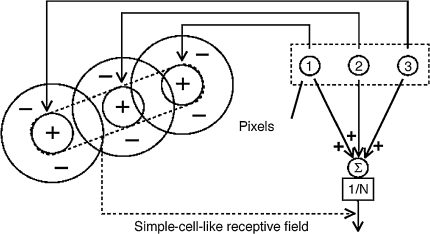
As described in the pioneering research of Hubel and Weisel, simple cells in the visual cortex (V1) are selective for local orientation and there are excitatory lateral connections between neurons of V1 with similar orientation (Hubel and Wiesel 1962). Here we use a feed-forward connection as a basic structure to simulate orientation selectivity in visual cortex V1, as shown in Fig. 1. Although this model does not thoroughly explain all properties of a simple cell, we hope this configurable model can help neuroscientist to run computational experiments to qualitatively study primate visual cortex.
Fig. 1.
A feed-forward model proposed by Hubel and Wiesel. The multiple pixels, located on a dash rectangle block indicate a straight line. The neurons temporal firing rates with preferred orientation are averaged (N is the number of total aggregated neurons). The receptive field present on this figure is only from ON channels. The OFF channel inputs can be obtained using the same way and be combined with ON channels
The digitalized data transfer from host machine to a FPGA board is via PCIe bus. The FPGA board consists of a two-dimensional array of neurons representing the cortical surface, virtually connected to an input image array that represents a receptor surface. In order to deal with realistic images at least with 512 × 512 gray-value images, a total 480,000 neurons need to be implemented for four different types of orientation selectivity. Therefore, the overall system needs 1 M neurons with 2 M synapses. Even with the latest FPGA technology, we cannot accommodate such lager neural network into a single FPGA device. A multiple-FPGA system is developed to partition the image into four parts: upper, lower, left, right. Four parts of image will be implemented into four FPGA devices respectively. In the case of deployment on Xilinx virtex-4, up to 64 spiking neuron processing units have been implemented. Using time division multiplexed scheme, the total of four FPGA devices emulate 1 M “virtual” neurons and 2 M synapses.
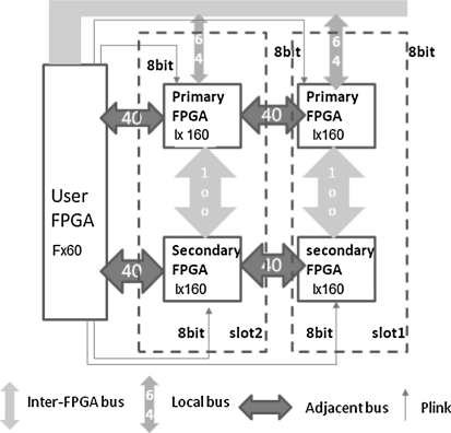
The development board we used is a PCIe-based board Benney from Nallatech with four virtex-4 family FPGAs (Nallatech Ltd 2006) populated. The board includes a user FPGA (V4FX60) implementing PCIe bus function. The block diagram of the multiple-FPGA system used in this work is illustrated in Fig. 2. The input image stimuli are read out pixel by pixel and converted to 16-bit digital signals. The digitalized signals are sent to the FPGA devices where external currents input for spiking neural models are produced. Two Gaussian-type filters are implemented on each FPGA device to create a parallel model of the regular spatial distribution of Lateral Geniculation Nucleus (LGN) cells (one on–off centre and one off–on centre per pixel). Multiple outputs for different orientation preferences are generated on the FPGAs located in slot1.
Fig. 2.
Block diagram of multiple-FPGA system. The system includes four FPGA devices (XC4VLX160) which are responsible for aggregating multiple pixels from the input images, mimicking a feed-forward model. A multi-FPGA system in which virtual connections form a two-dimensional array of receptors onto a set of neurons on a multiple-chip system mimic the feed-forward visual cortex. The host machine talks to the board through a local bus. The primary FPGA and secondary FPGA are application FPGA (XC4VLX160). The 40bit adjacent bus transfers signals into the neighboring chip if the spikes are generated. The high bandwidth bus with 100 bits at 200 MHz is used as inter-chip transmission
Throughout the development of the simulation of a primate visual cortex based on spiking neural network model, it is necessary to have a method to create various networks, debug their behavior, and further develop a fully-functioned primate visual system. With these goals in mind, a design-time configurable environment is provided so that users are able to arrange components and configure their properties without knowing HDL programming details. A user-friendly graphic user interface (GUI) is implemented, which aims to provide an easy method of configuring and controlling simulations for a wide user base of neuroscientists. There are a set of configurable parameters, such as number of neurons, synapses weight bits, programmable timer, connectivity, synapses-to-neuron ratio in spiking neural network simulation and communication FIFO length in FPGA-based configuration. The whole design also uses top-down hierarchy architecture so that various neuron modules with our customised interface can be plugged into the top modules. For instance, the current design is using leaky IF modules, alternatively, Izhikevich modules can be explored as well (Izhikevich 2003).
Neuron model
The first scientific model of a spiking neuron was proposed by Hodgkin and Huxley (1952). This model describes the neuron membrane potential in terms of the dynamic behaviour of the various ion channels (Hodgkin and Huxley 1952). However, these models contain so many parameters that it is frequently difficult to make any meaningful exploration of the available parameter space (Dayan and Abbott 2001). A leaky Integrate-and-Fire (LIF) neuron model, as one of the most basic formalisms of the spiking behavior of neurons, is used in this work (Burkitt 2006). Classical IF neuron model is in a form of differential equations (Gerstner and Kistler 2002). We use forward Euler integration to convert over discrete time-steps. The equations for neuron firing are:
 |
where Vm is the membrane potential, Vm(n−1) is the membrane potential at the previous time instant, Vl(τ) is the exponentially decreasing leaky voltage with time constant τ. The equation for Vs(n) synaptic integration is:
 |
where Vs in the synaptic input contribution to the membrane potential, Ns is the number of synapses, Wi are the synaptic weights, and Xi(n) denotes the arrival of per synaptic spike on input i at time n.
A block diagram of an individual LIF neuron is shown in Fig. 3. The membrane potential of the LIF neuron is implemented as a 16-bit accumulator. When the accumulator exceeds a threshold, a spike output is delayed with a programmable setting which models the axonal delay. The membrane potential resets to the user-specified reset value soon after the firing and in the absence of input spikes the membrane potential decays exponentially towards resting potential. The exponential decay function is implemented with lookup tables that have pre-calculated exponential decay values stored.
Fig. 3.
A block diagram of a single neuron model. A basic neuron contains three things: weight and delay, input spike activation function. The activation function take decision of output depended on the sum of all product terms, and this product depends on input and initial weights. The spike output is generated by a binary output 0 when the membrane voltage is below the threshold and 1 when it is above it. This signal is fed to the output register and is combined with the refractory control signal to ensure that the threshold is passed and an output spike is signalled. After that, the neuron membrane voltage is restored to its reset value
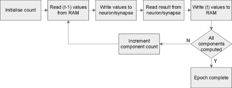
Due to the logical resource limitation on FPGA devices, there are only 64 neuron processing units implemented. Using time division multiplexed scheme, each of which emulate 256 K “virtual” neurons and 2,304 K synapses. The update period of the all neuron processing units on one FPGA device is set at 800 μs, which constitutes a real-time update period for biologically plausible spiking neural network. A flow diagram for this process is shown in Fig. 4.
Fig. 4.
A flow diagram of the time division multiplexing scheme. With time step 1 ms, each loop could be 1000 iterations when FPGA running at 100 MHz. Each neuron processing units read neuron data and synapses weights from off-chip RAM and accumulated membrane potential according to current time step value on each iteration. The calculated values are stored in off-chip RAM after one epoch completes
Response generation for orientation selectivity
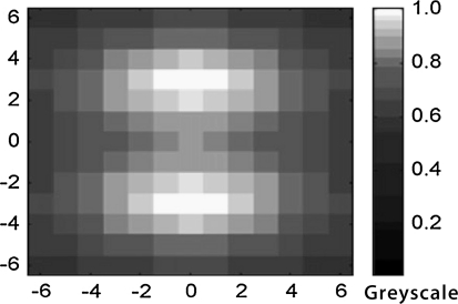
The receptive field depicted to the Fig. 5 is illustrative of one type of receptive field known as the Simple Cell (Hubel and Wiesel 1962). In this particular cell, the inhibitory region is located in the center, not on the sides.
Fig. 5.
The images (of pixel resolution 100 × 100) on the left show Gaussian-type filter kernels with values of the orientation parameter of 0°. The values of the other parameters are as follows: δa = 5, δb = 6, xc = 0, yc = 0 and ø = 0
Using the location as the center, the weights of two pixels are then calculated from the Gaussians function. The distribution of the receptive field is governed by Eq. 1. The weight Wxy from pixel (x, y) in the receptive field of an image pixel (a, b) with center (xc, yc) is given by
 |
1 |
where  determine the width along the major and minor axis of the Gaussian, and ϕ its orientation. Xc, Yc is the center of receptive field. The ratio of
  to
to  determines the orientation sensitivities.
In FPGA design, we implement an approximation of the Gaussian function using cascading multiple simple filters. Four consecutive FIR filters (generated by Xilinx Coregen 10.1) provide a good approximation to a Gaussian filter.
Inter-FPGA communication
Much research has been done on developing communication interfaces for neuron processing. However, the existing designs either provide extra functionality that is not required for this feed-forward network connection, or are not freely available. For those reasons, we propose a spike-driven communication controller that sends and receives spike data to the neighbouring FPGA devices. The controllers orchestrate data movement to neighbouring FPGA devices.
These communication controllers contain the logic to form spike data packets and generate all necessary handshaking signals. The communication controllers also comprise transmitter, receiver interfaces and asynchronous FIFO to forming two directional channels. Both these transmitter and receiver interfaces have 32-bit wide data bus, end-of-packet signal and handshaking signals.
Most neurons have a large number of inputs and output due to the all-to-all connectivity. Translating this aspect to the case of communication controller, the communication controller may have a larger FIFO on the receiver side and transmitter side. A current implementation of communication controller contains eight 32bit FIFOs. This can be configured during simulation to an appropriate size, depending on the logical resources of FPGA devices.
Configurable computing
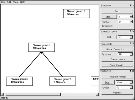
A design-time configure interface in our implementation enables our prototype hardware to be configured with various network and simulation parameters. The GUI interface features several options we have found useful for debugging a spiking neural network. Those options are the number of inputs, the number of output neurons and the number of synapses, the ratio of synapse-to-neuron, the number of communication FIFO, the population of neurons, the type of connectivity, the simulation time and the programmable timer (Fig. 6).
Fig. 6.
A main screen of GUI interface. The GUI interface is design for drag and click model. The neuron connectivity, synapse-to-neuron ration and the number of neuron in each group are configurable. A programmable timer can be configured in drag menus
Our hardware neural network platform has been implemented as parameterised modules using VHDL generic options. To create a parameterised logic function in VHDL, the logic function’s entity declaration includes a generic clause that lists all parameters (or “generics”) used in the logic function and their optional default values. Any users can instantiate a parameterised function with a component instantiation statement in the same way as un-parameterised functions.
On the modules qualification point of view, the proposed modules have passed both the HDL coding check following the Xilinx coding guidelines. We use synopsys LEDA as the checking tool to examine the generated RTL code. When the proposed HDL program is be qualified without any error, the floor planning and place-and-route included in the synthesis process can be done using Xilinx free-licence develop tool ISE9.1i. The pre-designed and reusable hardware modules or blocks easily reduce hardware turnover time.
Results
Dynamics of spiking neuron
We tested network dynamics by a three-layered feed-forward network with fixed connection weights and random delay. In the layer 1: one input neuron is injected with a fixed interval spike train which makes first layer fire at ~100 Hz; In the layer 2: 32 neurons are fully connected with layer 1 to form a one-to-all connectivity; in the layer 2 and layer 3: two populations of 32 Neurons are fully connected. Each population of neurons has two groups: 22 excitatory neurons and 10 inhibitory neurons. Each excitatory neuron is with a random delay range from 10 to 20 ms. Each inhibitory neuron is with a random delay of 20–80 ms. Excitatory weights are set in order to build up the background activity of the network slowly. Once there is sufficient activity, the whole excitatory group starts firing, causing the inhibitory neurons to fire a few milliseconds later (due to the long delay).
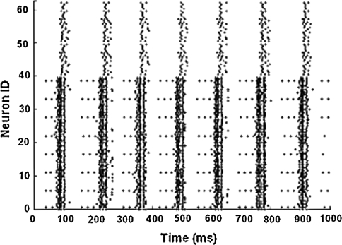
Figure 7 presents the results of the simulation. In this experiment, we aim to design a simple feed-forward circuit to test the 64 neurons and 1,024 synaptic connections (32 × 32) functionality. In a feed-forward network, the neural activity remained primarily driven by the external inputs and most neurons discharge at the same time synchronously. As shown in Fig. 7, the neural activities are propagated into the next layer through a feed-forward connection. Since there are fewer inhibitory neurons than excitatory neurons, neurons are tuned to have higher firing rates firstly. Since the inhibitory neurons connect to the excitatory neurons, their firing shut down the burst periodically after few milliseconds. This result shows that our multiple-FPGA system can successfully integrate membrane potential, generate spikes (if fire) and propagate spike activity through three layers.
Fig. 7.
A spike raster of the 64 neurons simulation. Experiment result shows synchronization of firing activity in a spiking neural network simulation in 1 s biological time
Effect of orientation selectivity
To help easily investigate the results of the FPGA accelerator, we develop a map to visualise those results. Implementing post-processing algorithms in this design significantly reduces I/O bandwidth requirements and thus enables a more efficient utilization of the hardware accelerator. The data that is required for the representation can be received by downloading the appropriate weight vectors from the external SRAM to the host machine. Additional software has been implemented to represent the corresponding synaptic weights value. The matrix of these values can be visualized e.g. a grayscale picture whose brightness area are depict high firing rates and whose dark areas represent low firing rates.
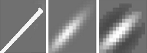
The global selectivity of the receptive field can be visualised similar to biological orientation maps. A response to bar of a preferred orientation is measured and recorded. As shown in Fig. 8, the white bar is oriented at 45°. The preferred orientation of receptive field is also 45°. In the case, the preferred orientation matches the orientation of the presented bar, the output gives rise to relatively clear responses in which the excited region and inhibitory region are seen side by side, in a configuration similar to that of the simple cells.
Fig. 8.
Example input and response of a bar. A 45° bar is an input image. The on-center response and the settled cortical V1 response are shown from left to right. The LGN responses are plotted in (left) by showing an average firing map of ON-channel. The output gives rise to relatively clear responses in which the excited region and inhibitory region are seen side by side
Neurobiologists have found that various receptive fields exist in the visual cortex (Kandel et al. 2000). The basic principle of orientations selectivity features in visual cortex might use receptive fields, tuned to particular orientations, to generate the orientations selectivity map of an input image. A 5 × 5 receptive field is a weight distribution of one of favored orientation with 5-rows-and-5-columns 2D array. The neuron array that has one orientation selectivity receptive field connected to the receptor array is 60 × 80. If we take an image with 512 × 512 pixel resolution, one neuron array includes 12 × 16 receptive fields.
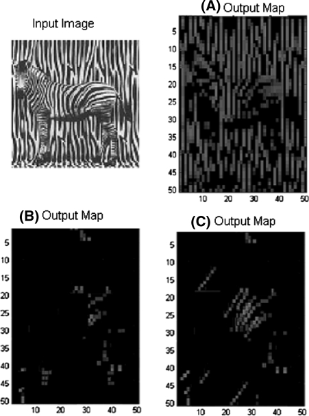
The response of the orientation selectivity to a zebra image was measured to examine how the proposed architecture performs for a real size image. Figure 9a, b represents the firing rates of vertical texture (90°) and horizontal texture (0°) of the zebra image matching two preferred orientations. The output map is patchy due to the fixed receptive field. These results are consistent with biological findings. The tuning selectivity will fade out along the activation path (Kandel et al. 2000). In Fig. 9c, the firing map is plotted as the 60° texture of preferred orientation. As we can see, the firing rates map of 60° is not accuracy with human observation. The discrepancy might be attributed to insufficient fixed size of receptive field. This observation conforms that the size of receptive field can be critical in the primate visual system.
Fig. 9.
Output image of the orientation responding to a zebra image. a Show the input image with resolution 512 × 512. b, c and d show the output image that was obtained with the preferred orientation of 0°, 90°, 60°, respectively
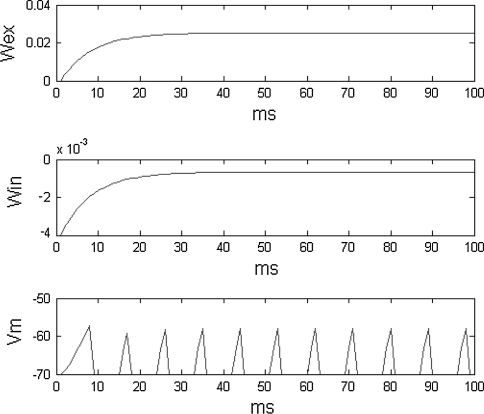
Figure 10 also shows the dynamics of one of neuron (30, 40) in the arrays during a 100 ms biological time period. The firing rate of a neuron is calculated within a period 100 ms. A set of typical parameter for these experiments is as follows: vth = − 60 mv, vreset = − 70 mv, wex = 0.0023, Win = − 0.0025, τex = 8 ms, τih = 8 ms. These parameters are adopted for neurons to perform specific function in the proposed network, which are consistent with biological results (Hodgkin and Huxley 1952).
Fig. 10.
The output image is the firing rate with vertical orientation selectivity. The membrane potential and synapse weights of neuron (30, 40) are recorded
Simulation speed
We run a simulation based on 512 × 512 pixel images to evaluate the simulation performance. The time required to perform on Intel Duo core 3.3 GHz in Matlab is 19.2 s for 500 ms real time while the FPGA based simulation requires 2.13 s (Table 1).
Table 1.
The software and hardware processing time
| Selectivity | Hardware | Software |
|---|---|---|
| 2 Orientations | 2.13 s | 19.2 s |
| 4 Orientations | 2.13 s | 38.4 s |
| 8 Orientations | 2.13 s | 76.8 s |
It should be noted that for the software simulation, increasing the number of orientations would result in an increase in the simulation times as the same processor must be used to process the data serially. For the FPGA implementation however, the simulation time would remain the same due to the fact that multiple processors can be designed to operate in parallel for each additional orientation. It is of note that the time division multiplexing scheme used in this work has impact on the computing speed.
The target FPGA in this instance is four Xilinx Virtex 4 devices. For each FPGA device, the implemented design consumed a total of 7,434 of the available 67,584 slices (11%), 30 of the 528 dedicated multiple blocks (24%) and 502 of the 628 BRAM (80%). The place and route tools reported that the requested 200 MHz system clock timing constraint was successfully achieved and this clock frequency was used for the actual hardware implementation. Based on Integrate-and-Fire model our approach is successfully used to implement topologies containing 1 M neurons and 2 M synapses.
Discussion
Related work
Given the reconfigurable nature of FPGA technology, there exist significant opportunities to use FPGA devices to obtain hardware optimised performance while maintain the inherent natural parallelism properties of biological neural arrays (Omondi 2006). One of the earliest instances of a spiking neural network implemented on FPGA hardware was reported by Rossmann et al. (1996). Another application of image segmentation has been implemented on FPGA system using an integrated-and-fire based local excitatory global inhibitory oscillator network model (Chen and Wang 2002). The authors report the hardware implementation is capable of performing segmentation at a higher speed than a PC based solution. This model uses neural oscillator receiving visual stimuli from pixels of the input image. As there is a direct correlation between the dimension of neural oscillator array and the input image resolution, real images has a significant amount of data lost.
One approach that provides a similar level of functionality to our approach is to use an optical front-end and FPGA as a combined system (Li et al. 2010). The authors exhibit biologically realistic simple-cell-like response properties, including highly modulated Poisson spike trains, orientation selectivity, spatial/temporal frequency selectivity, and space–time receptive fields using FPGA platform. This project aims to help setting- up electro-physical experiments in neurobiological teaching. The reported experiments only use standalone neuron mode.
Function of primate visual cortex
It is relatively easy to construct a spiking neural network model and observe its dynamics, but it is much harder to develop a model with stable behavior that computes a specific function using spiking neural networks (Hubel and Wiesel 2004). A top-down hierarchy model of primate visual system was implemented in this work in order to study function of various visual sub-systems within visual cortex. This experiment in primate visual systems is only used to observe the orientation selectivity, instead of temporal response function, spatial-temple frequency function which has been found in the primate visual cortex (Wörgötter and Koch 1991). Since the overall system architecture is the same and we can easily implement different receptive field modeling based on this established framework. A multiple-functioned neural network will be essential to many other important visual phenomena, such as visual attention, saccades between stimulus features (Hunt et al. 2011).
Feed-back from high level of visual cortex area
Current hierarchical visual processing model are purely feed-forward networks. We only simulated activation propagates from the LGN and to V1, but not in reverse direction. Although some physiologist believes that the feedback connections contribute top-down pattern completion, attention and large scale object grouping, the role of these feedback connections is not clear. As pre a previously described approach, feedback connections can be included in our proposed model using on-board end-to-end link (Nallatech Ltd 2006) since the address block used for this purpose has been marked Reserved in our system.
Large-scale of neural network
We demonstrated a programmable multiple-FPGA system that can be used for orientation selectivity in primate visual cortex with 1 M neurons and 2 M synapses.
However, the With spike-event based inter-chip connectivity, the system can be scaled into multiple FPGA cluster with minor changes. With multiple-FPGA cluster system, we might be able to find ways to map neural connectivity and hardware-demanding nonlinear functionality onto digital devices. Through our configurable hardware platform, we hope a computation paradigm could be defined to rise up the abstraction level and counterbalance the main implementation problems of large-scale spiking neural models.
Conclusion
This paper represents a configurable multiple-FPGA system for a primate visual system. We achieve two primary goals in this work. The first is to create an architecture that could support large scale network, given the results and figures presented it is evident that this has been achieved. The other goal is to develop a configurable method for incorporating biologically inspired neural network features. This system has advantages over software simulation in that the computational time does not scale with the level of the neural activity.
The long-term goal of this research is to create a programmable, general-purpose spiking-based visual processing platform that can be interfaced with any spike-event device with large-scale neural networks. It will be used for implementing real-time emulations of higher visual area. The particular application envisaged by this work is a multiple layer vision system that could receive its input from realistic images to implement cortical simple cells, complex cells, bipolar cells and finally view-tuned cells, according to the model of Weidenbacher and Neumann’s model. Currently, we have only implemented the first stage of processing in real-time. We are working towards a full implementation.
Acknowledgments
The authors thank to the financial support from National Science Foundation of China (Grant No. 60873047).
References
- Becker J, et al. Dynamic and partial FPGA exploitation. Proceeding of the IEEE. 2007;95:438–452. doi: 10.1109/JPROC.2006.888404. [DOI] [Google Scholar]
- Burkitt AN (2006) A review of the integrate-and-fire neuron model: I.Homogeneous synaptic input. Bio Cybern 95:1–19 [DOI] [PubMed]
- Chen K, Wang DL. A dynamically coupled neural oscillator network for image segmentation. Neural Network. 2002;15:423–439. doi: 10.1016/S0893-6080(02)00039-4. [DOI] [PubMed] [Google Scholar]
- Culurciello E, Etienne-Cummings R, Boahen KA. A biomorphic digital image sensor. IEEE J Solid-State Circuits. 2003;38:234–239. doi: 10.1109/JSSC.2002.807412. [DOI] [Google Scholar]
- Dayan P, Abbott LF (2001) Theoretical neuroscience: computational and mathematical modeling of neural systems. MIT press, Cambridge
- General Neural Simulation System (2010) http://www.genesissim.org/GENESIS/
- Gerstner W, Kistler W. Spiking neuron models: single neurons, populations, plasticity. Cambridge: Cambridge University Press; 2002. [Google Scholar]
- Girau B, Torres-Huitzil C. Massively distributed digital implementation of an integrate-and-fire LEGION network for visual scene segmentation. Neurocomputing. 2007;70:54–67. doi: 10.1016/j.neucom.2006.11.009. [DOI] [Google Scholar]
- Gokhale M, Graham PS. Reconfigurable computing: accelerating computation with field-programmable gate arrays. London: Springer; 2005. [Google Scholar]
- Gotarredona S, et al. CAVIAR: a 45 k neuron, 5 M synapse, 12G connects AER hardware sensory-processing-learning actuating system for high-speed visual object recognition and tracking. Trans Neur Netw. 2009;20(9):115–128. doi: 10.1109/TNN.2009.2023653. [DOI] [PubMed] [Google Scholar]
- Hodgkin AL, Huxley AF. A quantitative description of membrane current and its application to conduction and excitation in never. J Physiol. 1952;117:500–544. doi: 10.1113/jphysiol.1952.sp004764. [DOI] [PMC free article] [PubMed] [Google Scholar]
- Hubel D, Wiesel T (1962) Receptive fields, binocular interaction and functional architecture in the cat’s visual cortex. J Physiol (London) 160:106–154 [DOI] [PMC free article] [PubMed]
- Hubel DH, Wiesel TN. Brain and visual perception the story of a 25-year collaboration. New York: Oxford University Press; 2004. [Google Scholar]
- Hunt JJ et al (2011) Statistical structure of lateral connections in the primate visual cortex. Neural Syst Circuits 1:3 [DOI] [PMC free article] [PubMed]
- Izhikevich E. Simple model of spiking neurons. IEEE Trans. Neural Networks. 2003;14:1569–1572. doi: 10.1109/TNN.2003.820440. [DOI] [PubMed] [Google Scholar]
- Kandel E et al (2000) Principle of neuroscience, Elsevier
- Koch C (1999) Biophysics of computation: information processing in single neurons. Oxford University Press, Oxford
- Li G, et al. A FPGA real-time model of single and multiple visual cortex neurons. J Neurosci Methods. 2010;193:62–66. doi: 10.1016/j.jneumeth.2010.07.031. [DOI] [PubMed] [Google Scholar]
- Löwel S (1994) Ocular dominance column development: strabismus changes the spacing of adjacent columns in cat visual cortex. J Neurosci 14:7451–7468 [DOI] [PMC free article] [PubMed]
- Nallatech Ltd (2006) BenNYEY-PCI-X-V4 Reference Guide, ver1, NT107-0273
- Neuron Software Simulator Tool (2010) http://www.neurosolutions.com/products/ns/
- Omondi AR (eds) (2006) FPGA Implementations of neural networks. Springer, London
- Patterson DA, Hennessy JL. Computer architecture: a quantitative approach. San Francisco, CA, USA: Morgan Kaufmann Publishers Inc; 2003. [Google Scholar]
- Rossmann M et al (1996) Implementation of a biologically inspired neuron-model in FPGA. In: Proceedings of fifth international conference on microelectronics for neural networks, pp 322–330
- Satoh S, Usui S (2008) Engineering-approach accelerates computational understanding of V1–V2 neural properties, 7, 2008. 11(7):1959–1979; Cogn Neurodyn. 2009 March; 3(1):1–8 [DOI] [PMC free article] [PubMed]
- SpikeNET Neural Network Simulator (2011) http://www.spikenettechnology.com/
- Wandell BA, editor. Foundations of vision. Sunderland, MA: Sinauer Associates Inc; 1995. [Google Scholar]
- Upegui A et al (2004) A hardware implementation of network of functional spiking neurons with Hebbian learning, biologically inspired approaches to advanced information technology, LNCS. Springer Berlin, pp 233–243
- Wildie M et al (2009) Reconfigurable acceleration of neural models with gap junctions. In: Proceeding of field-programmable technology
- Wörgötter F, Koch C. A detailed model of the primary visual pathway in the cat: comparison of afferent excitatory and intracortical inhibitory connection schemes for orientation selectivity. J Neurosci. 1991;11(7):1959–1979. doi: 10.1523/JNEUROSCI.11-07-01959.1991. [DOI] [PMC free article] [PubMed] [Google Scholar]


