Abstract
The objective of this study was to prepare dense zirconia-yttria (ZY), zirconia-silica (ZS) and zirconia-yttria-silica (ZYS) nanofibers as reinforcing elements for dental composites. Zirconium (IV) propoxide, yttrium nitrate hexahydrate, and tetraethyl orthosilicate (TEOS) were used as precursors for the preparation of zirconia, yttria, and silica sols. A small amount (1–1.5 wt%) of polyethylene oxide (PEO) was used as a carry polymer. The sols were preheated at 70 °C before electrospinning and their viscosity was measured with a viscometer at different heating time. The gel point was determined by viscosity–time (η–t) curve. The ZY, ZS and ZYS gel nanofibers were prepared using a special reactive electrospinning device under the conditions near the gel point. The as-prepared gel nanofibers had diameters between 200 and 400 nm. Dense (nonporous) ceramic nanofibers of zirconia-yttria (96/4), zirconia-silica (80/20) and zirconia-yttria-silica (76.8/3.2/20) with diameter of 100–300 nm were obtained by subsequent calcinations at different temperatures. The gel and ceramic nanofibers obtained were characterized by scanning electron microscope (SEM), high-resolution field-emission scanning electron microscope (FE-SEM), thermogravimetric analyzer (TGA), differential scanning calorimeter (DSC), Fourier transform infrared spectrometer (FT-IR), and X-ray diffraction (XRD). SEM micrograph revealed that ceramic ZY nanofibers had grained structure, while ceramic ZS and ZYS nanofibers had smooth surfaces, both showing no visible porosity under FE-SEM. Complete removal of the polymer PEO was confirmed by TGA/DSC and FT-IR. The formation of tetragonal phase of zirconia and amorphous silica was proved by XRD. In conclusion, dense zirconia-based ceramic nanofibers can be fabricated using the new reactive sol–gel electrospinning technology with minimum organic polymer additives.
Keywords: Reactive Electrospinning, Zirconia, Silica, Ceramic Nanofiber, Dental Composite
1. INTRODUCTION
Resin-based dental composites have been widely used in dentistry to restore carious teeth because they are tooth-colored and lack of hazardous metals. But composites may have shorter life than amalgams. The two leading causes for the failure of dental composite restorations in clinic are secondary (recurrent) caries and bulk fracture.1–2 To reduce secondary caries, research efforts have been directed towards the development of dental composites that release anti-caries agents (F−, Ca2+ and ions). Despite significant development in this area, the dental composites reinforced with particulate fillers, particularly those releasing anti-caries agents, still have inadequate strength and fracture toughness. To overcome the fracture problem, various high strength, high modulus fibers have been used to improve the strength and fracture toughness of composites.3–8 Such fibrillar materials include polyethylene, glass fibers,9–12 ceramic (SiC and Si3N4) whiskers13–16 and silica nanofibers.17 Incorporation of these fibers can significantly increase stiffness, flexure strength, fracture toughness and fatigue resistance of the composites, but chemical stability, esthetics and handling properties of these materials are unsatisfactory. Fabrication of composite restorations reinforced by long polyethylene or glass fibers is technique-sensitive and time-consuming. Composites reinforced with glass fibers exhibit relatively low long-term mechanical properties after prolonged storage in water. For example, the flexure strength and modulus of a commercial dental composite, DC-Tell (DCS Dental, Finland), which contains 38% short glass fibers, decreased 66% and 60% respectively after storage in water for 3 months.12 Ceramic fibers or whiskers usually have superior chemical resistance and thermal stability as well as excellent mechanical property. It was reported that incorporation of ceramic (SiC and Si3N4) whiskers in dental composites could lead to a two-fold increase in strength and toughness, as well as provide promising results in composite polishability, water absorption, and strength durability.13–16 However, such composites cannot be light-cured (photopolymerized) due to the high opacity (light scattering effect) of the whisker-reinforced composites caused by the large difference of refractive index between the whiskers (2.2–2.7) and the resin matrix (1.53). In general, tooth-colored, light-curable fiber-reinforced dental composites with high strength and toughness for direct restoration are highly desirable and have not been available. New fibrillar materials are needed for such dental composites.
The objective of this study is to prepare dense zirconia-yttria (ZY), zirconia-silica (ZS) and zirconia-yttria-silica (ZYS) nanofibers as reinforcing elements for dental composites. The rationales for using zirconia-based ceramic nanofibers are:
zirconia-based ceramics have high toughness, good chemical stability and biocompatibility;
nanofibers (diameters < 200 nm) may reduce light scattering as well as increase mechanical properties and polishability;
ZS and ZYS ceramic nanofibers consisting of crystalline zirconia and amorphous silica may offer combined advantages of high toughness and chemical stability of zirconia, and lower refractive index and good surface coupling ability of silica, which is important for making a high performance dental composite.
Several research groups have reported fabrication of zirconia nanofibers by electrospinning technology from different precursors.18–24 This process mainly includes the following three steps:
preparation of a sol with suitable precursor and polymer content, and suitable viscosity;
electrospinning of the sol to prepare polymer/inorganic gel fibers;
calcinations of the gel fibers to obtain the target ceramic fibers.
However, the zirconia nanofibers made by such methods may be porous and may have low strength because a high amount (5–20 wt%) of polymers (e.g., polyvinyl alcohol or polyvinylpyrrolidone) was added to the sol to aid the electrospinning process and the voids formed after the removal of the polymers during calcination may not be completely healed. Such porous ceramic nanofibers may be useful for such applications as catalyst support and fuel cells, but they can not be used in the reinforcement applications such as in dental composites.
In this paper, we report the fabrication of dense zirconia-based ceramic nanofibers including ZY, ZS and ZYS nanofibers by a novel reactive sol–gel electrospinning technology. The reinforcement of dental composites using these nanofibers will be reported later.
2. EXPERIMENTAL DETAILS
2.1. Materials
Zirconium (IV) propoxide (70 wt% solution in 1-propanol), anhydrous 2-propanol, yttrium nitrate hexahydrate, tetraethyl orthosilicate (TEOS, 98%), hydrochloric acid, polyethylene oxide (PEO, Mz ≈ 400,000) were purchased from Sigma-Aldrich and used without further purification.
2.2. Preparation of Zirconia, Yttria and Silica Sols
2.2.1. Zirconia Sol
A mixture of deionized (DI) water (18 g, 1 mol), concentrated nitric acid (70.2 wt%, 8.98 g, 0.1 mol) and anhydrous 2-propanol (50 mL) was added dropwise to zirconium (IV) propoxide (70 wt% solution in 1-propanol, 46.80 g, 0.1 mol) in anhydrous 2-propanol (200 mL). The resulting mixture with dense precipitates was concentrated to about 100 mL. DI water (600 mL) was then added, and the mixture was further stirred overnight. Most of the precipitates dissolved, a few residual precipitates were removed by centrifugation. The clear solution was concentrated to about 50 mL, and then adjusted to 1.0 M, 1.5 M, or 2.0 M ZrO2 by either further concentrating or diluting with DI water.
2.2.2. Yttria Sol
Yttrium nitrate hexahydrate (4.79 g, 12.5 mmol) was dissolved in DI water (50 mL), and titrated with ammonia solution (4 wt%) until pH 9.5. White precipitates were collected by filtration, and washed with DI water. Then the solid was mixed with nitric acid (0.5 M, 25 mL) and stirred overnight, giving a milky yttria solution (0.25 M).
2.2.3. Silica Sol
TEOS (1.5 g, 7.2 mmol) was mixed with hydrochloric acid (0.5 M, 1.5 g), and stirred vigorously until a homogeneous solution was obtained (about 30 min). The solution was immediately used for the preparation of nanofibers.
2.3. Electrospinning Device
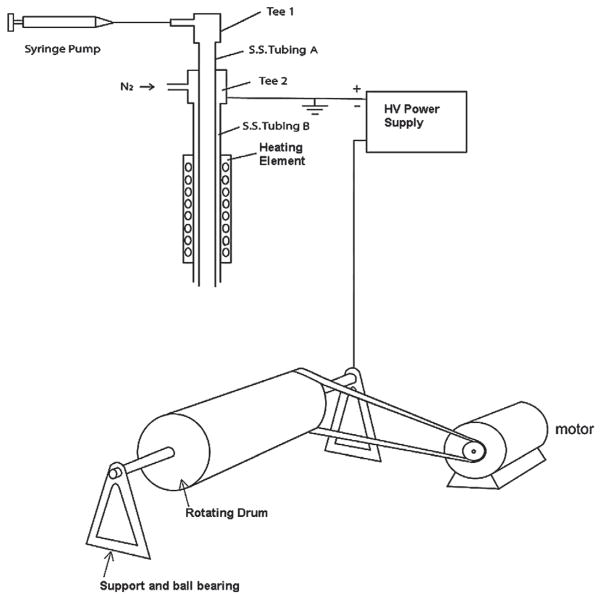
A new reactive electrospinning device has been designed as shown in Figure 1. The device consists of
Fig. 1.
Schematic drawing of the reactive electrospinning device.
a heated coaxial electrospinning spinneret, which consists of a capillary tubing A (stainless steel, outside diameter 0.0355 inches) for delivery of the electrospinning solution and an outer tubing B (stainless steel, outer diameter 0.065 inches) coaxially outside capillary tubing A to introduce pressured gas (nitrogen, steam of the solvent, etc.),
an adjustable transformer to provide power to the coil heater on the spinneret,
a digital thermometer with a thermal couple to monitor the spinneret temperature,
a rotating cage (7 inches long, 3.5 inches in diameter) to collect the nanofibers,
a DC motor (model ECmax30, Maxon Precision Motors, Inc. Fall River, MA) to drive the rotating cage through a rubber belt;
an electronic motor controller (DEC 70/10, Maxon Precision Motors, Inc. Fall River, MA) to control and adjust the rotating speed of the rotating cage (0–1500 rpm),
a 24 V rechargeable battery to provide power to the motor,
a 60 KV high voltage power supply (Model D–ES60N-30P/M1027, Gamma High Voltage Research, Inc., Ormond Beach, Fl) to apply high voltage to the rotating cage, and
a syringe pump to deliver the solution for electrospinning.
2.4. Fabrication of ZY, ZS and ZYS Nanofibers
A small amount (1.0 wt% or 1.5 wt%) of PEO was added to the mixed zirconia-yttria sol (molar ratio 96/4) or zirconia-silica sol (molar ratio 80/20) or zirconia-yttria-silica sol (molar ratio 76.8/3.2/20). Before electrospinning, one batch of the mixture was stirred at room temperature for about 30 min, and then heated at 70 °C for 5 hours. During this time, the viscosity of the mixture was measured at different time with Brookfield Synchro-Lectric LV viscometer and a small sample adaptor SC4-18/13R (Brookfield Engineering Lab, Middleboro, MA). The resulting viscosity–time (η–t) curve was used to determine the gel point (time) when the viscosity increased dramatically. Another batch of mixed sol was heated at 70 °C under stirring up to 20–30 min before the determined gel time or when the viscosity reached 300–500 cP. The resulted viscous sol was delivered using syringe pump with a flow rate of 0.5–3.0 mL/h. The electrospinning needle was heated at 70 °C, and nitrogen gas (20 psi) was introduced through Tee 2 and between the inner tubing A and outer tubing B. A high voltage of 20–50 kV was applied. The nanofibers were collected on the rotating cage (covered with aluminum foil) which was located at 12 cm in distance from needle tip to the surface of the cage. The rotating speed was controlled between 300 rpm and 1400 rpm. The fibers thus formed were initially dried under a 150 W heat lamp for 30 min on the cage, and then in a 110 °C oven overnight. After that, the dried fibers were calcinated in a tube furnace (Cat No. STF54434C, Fisher Scientific, Houston, TX) using the following procedure: Temperature was increased to 500 °C from room temperature at a heating rate of 5 °C/min, soaking at 500 °C for 1 hour, then increased to different temperature (800 °C, 1200 °C, 1400 °C) at a heating rate of 10 °C/min, soaking for 30 min at the final temperature and cooling down with the furnace.
2.5. Characterization of the Nanofibers
SEM (Hitachi 2700) and FE-SEM (Hitachi 4800 FE-SEM, Tokyo, Japan) were used for the observation of the morphology of nanofibers. XRD patterns of the samples were recorded by a Scintag XDS 2000 Diffractometer, scans were made from 10° to 70° (2θ) at a speed of 2°/min, using Ni-filtered Cu Kα. Simultaneous high temperature thermal gravimetric analysis (TGA) and differential scanning calorimetric (DSC) analysis was performed on SDT Q-600 (TA Instrument/Waters, New Castle, DE) from 30–1400 °C at a heating rate of 20 °C/min in nitrogen atmosphere. Fourier-transformed infrared (FT-IR) spectra were recorded on NEXUS 670 FT-IR spectrometer (Thermo-Scientific, Madison, WI) with a Golden Gate diamond attenuated total reflection (ATR) accessory (Specac Inc., Woodstock, GA).
3. RESULTS AND DISCUSSION
3.1. Reactive Electrospinning Device and Method
Dense (non-porous) zirconia-based ceramic nanofibers are needed as reinforce elements for composites. However, current methods for making zirconia nanofibers by electrospinning technology require a significant amount (5–20 wt%) of organic polymer to be added to the zirconia sol due to its poor spinability at ambient temperature. As a result, the ceramic nanofibers obtained after calcination may have significant porosity after removal of the organic polymers. To obtain dense (non-porous) zirconia ceramic nanofibers, the amount of organic polymer added must be minimized. To solve the problem of poor spin-ability of zirconia sol, we have designed and constructed a new reactive electrospinning device (Figs. 1 and 2) and developed a reactive electrospinning method.
Fig. 2.
Reactive electrospinning device.
This new electrospinning device has the following features:
The spinneret is heated at elevated temperatures (30–150 °C) by a coil heater wrapping around it. This elevated temperature can induce or accelerate chemical reactions (e.g., sol–gel transition process), lower the viscosity, and facilitate the evaporation of the solvent.
Pressured gas is introduced coaxially outside the spinneret (capillary tube A), which can help to “split” the viscous solution jet into fine fibers, assist the evaporation of the solvent, and dry the fibers.
The heated spinneret, motor, and motor controller are grounded while the collector (rotating cage) is at high potential.
Such a configuration can prevent the high voltage damage to sensitive electronic devices. The motor and motor controller are also grounded and isolated in a 4 × 4 × 10 inch acrylic box. The spinneret, rotating cage, motor and controller are located inside a 24×36×24 inch acrylic plastic box, as shown in Figure 2.
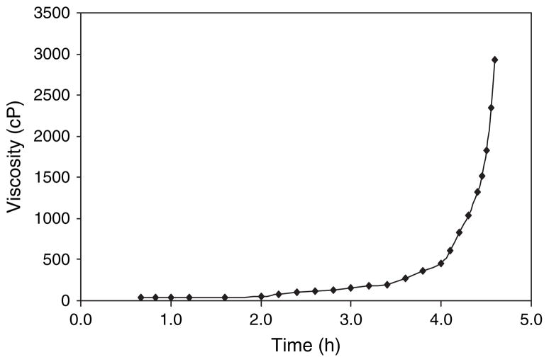
The viscosity of the electrospinning sol was very important to the generation of composite nanofibers. Below 170 cP, nanofibers contained a lot of beads. Above 3000 cP, the electrospinning process became unstable and the needle was frequently clogged. Figure 3 shows the viscosity changes of zirconia-silica sol (molar ratio 80/20) with heating time (η–t curve) at 70 °C. At beginning, viscosity slowly increased; while after about 4 hours, viscosity increased rapidly. Therefore, the gel point was determined to be around 4 hours. The most suitable viscosity for the electrospinning process was found to be 300–500 cP.
Fig. 3.
Viscosity of zirconia-silica sol (molar ratio 80/20) +1.5 wt% PEO with heating time at 70 °C.
In this study, the reactive sol–gel electrospinning method was used to fabricate the gel nanofibers (precursors for ceramic nanofibers). The sols were preheated and stirred until 20–30 min before the gel point, then they were electrospun, during which the sol–gel transition underwent under elevated temperature (70 °C). The sol–gel transition process was completed during post-spin heat treatment (drying under heat lamp and at 110 °C in the oven for overnight). Using this new electrospinning device and method, only a small amount of PEO (1 wt% or 1.5 wt%) is needed as a carry polymer in the sol and dense (nonporous) ceramic nanofibers can be obtained after calcination.
3.2. Morphology of Nanofibers
Diameter and porosity are important for the ceramic nanofibers to be used as the reinforcing element, because they may have significant influence on the mechanical property of the composite. In order to find the optimal conditions for fabricating thin and dense ceramic nanofibers, a series of electrospinning conditions, including voltage (20–50 KV), distance between needle tip and rotating drum (8–20 cm), liquid feeding rate (0.5–3.0 ml/h), rotating speed of drum (300–1400 rpm), conductivity of solution (addition of salts), concentration of zirconia (1 M, 1.5 M and 2 M) were tested. The diameter of the obtained gel fibers and ceramic fibers were measured using SEM. The results indicated that concentration of zirconia solution had influence on fiber diameter, while other factors do not exhibit significant effects on the diameters in our experimental ranges. Table I shows the diameters of ZS nanofibers prepared from zirconia-silica sol with different zirconia concentrations. As we had expected, the diameters of the as-spun gel fibers and the ceramic nanofibers increased with the increase of the ZrO2 concentration. Lower concentration solution gave thinner nanofibers but the fibers were not very uniform at the concentration lower than 1 M. A significant amount of beads appeared at ZrO2 concentration lower than 0.5 M (not shown). By optimization, the suitable condition for the electrospinning process is: ZrO2 sol: 1.5 M in concentration; distance between tip and drum: 12 cm; voltage: 30 KV; feeding rate: 1.5 mL/h; rotating speed of drum: 500 rpm.
Table I.
Diameter of ZS nanofibers prepared from different ZrO2 concentration solutions.
| ZrO2 concentration (M) | 1.0 | 1.5 | 2.0 | |
|---|---|---|---|---|
| Diameter (nm) | Gel fiber | 122 ± 27 | 242 ± 36 | 321 ± 23 |
| Ceramic fiber | 102 ± 21 | 194 ± 44 | 272 ± 25 | |
Silica sol: (50 wt%); Zr/Si: 80/20 (molar ratio); feeding rate: 1.5 ml/h; voltage: 30 KV; distance between needle tip and drum: 12 cm; rotating speed of the drum: 500 rpm.
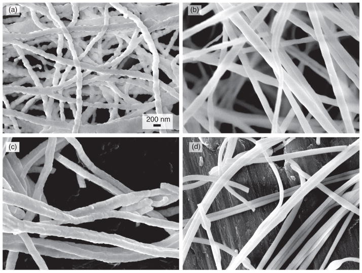
Figure 4 shows the FE-SEM images of various ceramic nanofibers. The average diameters of all three gel nanofibers (ZY, ZS and ZYS) are very similar (about 240 nm). After calcinations of the gel nanofibers at 1200 °C or 1400 °C, average diameters decreased to about 190 nm. Ceramic ZY nanofibers calcinated at 1200 °C and 1400 °C had similar morphology under FE-SEM, and grained structure due to formation of tetragonal crystalline phase was clearly observed as shown in Figure 4(a). These intersections among the grains in nanofibers may be potential mechanical weaknesses when ZY nanofibers are used as the reinforcement element of composites. In ceramic ZS nanofibers calcinated at 1200 °C, no grains were observed (Fig. 4(b)), and the surfaces were very smooth. On the other hand, relatively rough surfaces were observed on ZS nanofibers calcinated at 1400 °C (Fig. 4(c)), but no grains were clearly observed. Ceramic ZYS nanofibers calcinated at 1200 °C (Fig. 4(d)) and 1400 °C also had similar morphology, and no grain structures were detected. The likely reason that ZS and ZYS ceramic nanofibers did not have grain structure is that fusible amorphous silica suppressed the crystal growth and sealed the crystal grain boundary (see XRD analysis section for more details).
Fig. 4.
SEM images of (a) ceramic ZrO2-Y2O3 nanofibers (molar ratio 96/4) calcinated at 1200 °C; (b) ceramic ZrO2-SiO2 (molar ratio 80/20) nanofibers calcinated at 1200 °C; (c) ceramic ZS nanofibers calcinated at 1400 °C; (d) ceramic ZrO2-Y2O3-SiO2 nanofibers (molar ratio 76.8/3.2/20) calcinated at 1200 °C. (All fibers are electrospun from the sol containing 1.5 M ZrO2 and 1.5% PEO. All images have magnification of 50,000).
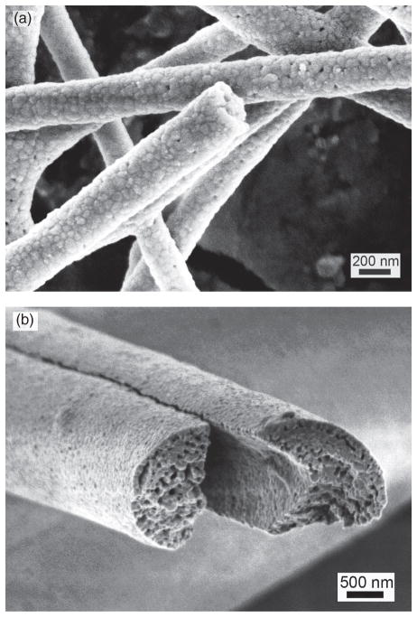
The amount of organic polymer added to the sol has a great influence on the porosity and morphology of the calcinated ceramic nanofibers. In all ceramic fibers made from the sol containing 1.5% or less organic polymers (e.g., PEO), no visible porosity was observed under FE-SEM, suggesting these fibers were nonporous (Figs. 4(a–d)). For organic polymer content greater than 5%, the pores are readily observed under FE-SEM, as shown in Figure 5. Also the diameter of the fiber increased, because the viscosity of the sol increased as the increase of the amount of organic polymer. Obviously, ZS and ZYS ceramic nanofibers calcinated at 1200 °C are good for the reinforcement of composites. Moreover, surface-modification of ZS and ZYS nanofibers is easier than that of ZY nanofibers, therefore, ZS and ZYS nanofibers calcinated at 1200 °C should be more useful in the reinforcement of composites than ZY nanofibers.
Fig. 5.
Scanning electron micrographs of yttria-zirconia nanofibers from sols containing (a) 5% PEO, (b) 7% PVP, both calcinated at 1200 °C.
3.3. Chemical and Structural Properties of Nanofibers
3.3.1. DSC/TGA Analysis
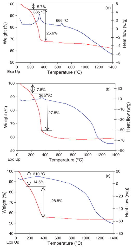
Figure 6(a) shows the DSC/TGA result of the ZY nanofibers. From room temperature to about 180 °C, weight loss was attributed to the release of physically absorbed water on the fiber surface. Weight loss between 180 °C and 400 °C corresponded to the decomposition of PEO. An exothermic peak at 666 °C was probably due to further decomposition of residual organic moieties in the nanofibers. Above 400 °C, sample weight only slightly decreased, indicating most of the organic moieties decomposed below 400 °C. Figure 6(b) shows the DSC/TGA result of ZS nanofibers. Almost all organic moieties decomposed below 600 °C. From about 650 °C, heat flow started to decrease (endothermic), corresponding to the formation of tetragonal zirconia crystalline phase. At about 1300 °C, heat flow curve tended to increase, probably indicating transformation from tetragonal phase to monoclinic phase.25 ZYS nanofibers had the similar curves (Fig. 6(c)) with ZS nanofibers in the DSC/TGA results below 1100 °C, but did not exhibit the tendency of increasing in heat flow curve below 1400 °C, suggesting ZYS did not transform to monoclinic phase.
Fig. 6.
DSC/TGA curves of (a) ZY, (b) ZS and (c) ZYS nanofibers. Samples were run in N2 atmosphere at a heating rate of 20 °C/min.
3.3.2. FT-IR Analysis
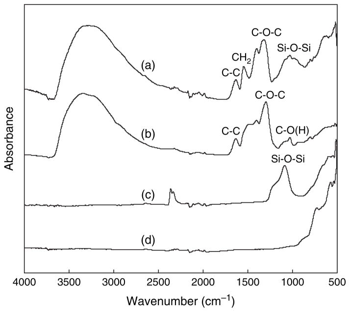
In order to confirm the formation of pure ZY, ZS and ZYS nanofibers after calcinations at high temperature with the complete removal of PEO, FT-IR spectra of both gel nanofibers and ceramic nanofibers were tested. The FT-IR spectrum (Fig. 6, curve (a)) of the as-prepared ZS gel nanofibers shows some strong absorptions in the region of 1200 to 1700 cm−1, corresponding to the stretching and bending vibration of CH2 and C–O–C in PEO. A broad absorption band at 1000–1200 cm−1 was attributed to the stretching vibration of Si–O–Si bonds. After calcinations at 1200 °C, the absorption band from Si–O–Si was still observed, while those absorption bands due to PEO disappeared, indicating complete removal of PEO from the ZS gel nanofibers (Fig. 7, curve (c)). The complete removal of PEO after calcinations in the ceramic ZY nanofibers was also confirmed by the disappearance of PEO absorption bands (Fig. 7, curves (b and d)). The FT-IR spectra of ZYS gel and ceramic nanofibers were similar to those of ZS and are not shown in Figure 7.
Fig. 7.
FT-IR spectra of (a) ZS gel nanofibers; (b) ZY gel nanofibers; (c) ZS ceramic nanofibers (calcinated at 1200 °C); (d) ZY ceramic nanofibers (calcinated at 1200 °C).
3.3.3. XRD Analysis
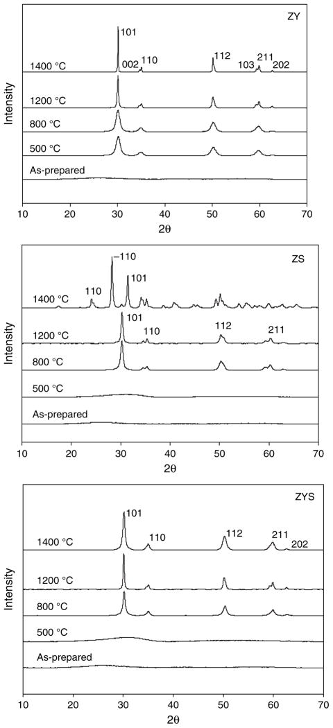
Figure 8 and Table II show the XRD results of ZY, ZS and ZYS nanofibers. All as-prepared nanofibers (ZY, ZS and ZYS) were amorphous. Ceramic ZY nanofibers were proved to be in tetragonal phase after calcinations at temperature between 500 °C and 1400 °C. A weak and broad peak at about 30 degree of 2θ was observed in both ZS and ZYS nanofibers calcinated at 500 °C, suggesting initial formation of tetragonal zirconia in these fibers. After calcinations at 800 °C and 1200 °C, both ZS and ZYS nanofibers transformed to tetragonal phase. While after calcination at 1400 °C, 99 wt% of zirconia in ZS nanofibers transformed to monoclinic phase, but zirconia in ZYS nanofibers was still in tetragonal phase possibly due to the stabilization effect by yttria. No crystalline silica peaks were detected in XRD spectrum, indicating silica in both ZS and ZYS nanofibers was amorphous. Table II also indicates that crystalline particle sizes of zirconia in ZY and ZYS nanofibers increased with calcination temperature but ZYS nanofibers calcinated at 1200 °C and 1400 °C have significantly smaller crystal size than ZY nanofibers at the same calcination temperature, and therefore, ZYS nanofibers are smooth while ZY nanofibers show grain structure and grain boundary (Figs. 4(a) and (c)). This indicates that the amorphous silica phase suppressed the crystal growth of the tetragonal zirconia phase. Similar result was obtained in ZS nanofibers, i.e., tetragonal crystalline particle sizes remain small (smooth fibers) and did not change significantly with the calcination temperature at or below 1200 °C. Without the stabilizing effect of yttria, however, the crystalline phases of ZS nanofibers are mostly monoclinic at calcination temperature of 1400 °C. The ceramic nanofibers with smaller crystal size and without grain boundary are preferable as reinforcing elements because they have less defects and better mechanical properties.
Fig. 8.
XRD patterns of ZY, ZS and ZYS nanofibers calcinated at 500, 800, 1200 and 1400 °C.
Table II.
Crystalline phase and particle size of zirconia in ZY, ZS and ZYS nanofibers measured by XRD.
| Sample | Calcination temperature (°C) | Crystal type
|
|||
|---|---|---|---|---|---|
| Tetragonal
|
Monoclinic
|
||||
| Weight (%) | Size (nm) | Weight (%) | Size (nm) | ||
| ZY | As-prepared | N/A | N/A | N/A | N/A |
| 500 °C | 100 | 1 | 0 | N/A | |
| 800 °C | 100 | 9 | 0 | N/A | |
| 1200 °C | 100 | 51 | 0 | N/A | |
| 1400 °C | 100 | 73 | 0 | N/A | |
| ZS | As-prepared | N/A | N/A | N/A | N/A |
| 500 °C | N/A | N/A | N/A | N/A | |
| 800 °C | 100 | 15 | 0 | N/A | |
| 1200 °C | 100 | 14 | 0 | N/A | |
| 1400 °C | 1 | 25 | 99 | 25 | |
| ZYS | As-prepared | N/A | N/A | N/A | N/A |
| 500 °C | N/A | N/A | N/A | N/A | |
| 800 °C | 100 | 12 | 0 | N/A | |
| 1200 °C | 100 | 21 | 0 | N/A | |
| 1400 °C | 100 | 41 | 0 | N/A | |
4. CONCLUSION
In this study, we have demonstrated that nonporous ZY, ZS and ZYS nanofibers with diameters of 100–300 nm can be prepared by a new reactive electrospinning technology with minimum organic polymer additive (1–1.5 wt%) and subsequent calcinations at high temperature. Viscosity of the electrospinning solution was important to the formation of the nanofibers. XRD and TGA/DSC tests proved the formation of tetragonal phase during calcination. FT-IR confirmed the complete removal of PEO from the gel nanofibers after calcination. SEM observation revealed that ceramic ZY nanofibers had grained structure, while ceramic ZS and ZYS nanofibers calcinated at 1200 °C had very smooth surfaces. Under this condition, the silica remains amorphous while zirconia is crystalline (mainly in tetragonal phase). Such ceramic nanofibers, particularly, ZS and ZYS nanofibers, may be used for reinforcement in dental composites and other composite materials. The new reactive electrospinning method may also be used to fabricate other crosslinked polymer nanofibers. This part of work is currently undergoing in our group.
Acknowledgments
This study is supported by the US National Institute of Health/National Institute of Dental and Craniofacial Research (NIH/NIDCR grant No. 1R21DE18349) and NIH/NCRR Center of Biomedical Research Excellence (COBRE) grant (grant No. 1 P20RR020160).
References and Notes
- 1.Mjör IA. Oper Dent. 1985;10:88. [PubMed] [Google Scholar]
- 2.Deligeorgi V, Mjör IA, Wilson NH. Prim Dent Care. 2001;18:5. doi: 10.1308/135576101771799335. [DOI] [PubMed] [Google Scholar]
- 3.Van Heumen CC, Kreulen CM, Bronkhorst EM, Lesaffre E, Creugers NH. Dent Mater. 2008;24:1435. doi: 10.1016/j.dental.2008.06.006. [DOI] [PubMed] [Google Scholar]
- 4.Tian M, Gao Y, Liu Y, Liao Y, Hedin NE, Fong H. Dent Mater. 2008;24:235. doi: 10.1016/j.dental.2007.05.002. [DOI] [PMC free article] [PubMed] [Google Scholar]
- 5.Kurunmäki H, Kantola R, HatamLeh MM, Watts DC, Vallittu PK. J Prosthet Dent. 2008;100:348. doi: 10.1016/S0022-3913(08)60235-8. [DOI] [PubMed] [Google Scholar]
- 6.Garoushi S, Vallittua PK, Lassilaa LVJ. Dent Mater. 2007;23:1356. doi: 10.1016/j.dental.2006.11.017. [DOI] [PubMed] [Google Scholar]
- 7.Garoushi SK, Lassila LV, Vallittu PK. J Contemp Dent Pract. 2006;7:10. [PubMed] [Google Scholar]
- 8.Garoushi SK, Lassila LV, Tezvergil A, Vallittu PK. J Con-temp Dent Pract. 2006;7:1. [PubMed] [Google Scholar]
- 9.Behr M, Rosentritt M, Latzel D, Kreisler T. J Dent. 2001;29:187. doi: 10.1016/s0300-5712(01)00007-0. [DOI] [PubMed] [Google Scholar]
- 10.Giordano R. Gen Dent. 2000;48:244. [PubMed] [Google Scholar]
- 11.Knobloch LA, Kerby RE, Seghi R, Berlin JS, Clelland N. J Prosthet Dent. 2002;88:307. doi: 10.1067/mpr.2002.128069. [DOI] [PubMed] [Google Scholar]
- 12.Lastumäki TM, Lassila LVJ, Vallittu PK. Int J Prosthodont. 2001;14:22. [PubMed] [Google Scholar]
- 13.XU HHK, Martin TA, Antonucci JM, Eichmiller FC. J Dent Res. 1999;78:706. doi: 10.1177/00220345990780021101. [DOI] [PubMed] [Google Scholar]
- 14.Xu HHK. J Dent Res. 1999;78:1304. doi: 10.1177/00220345990780070401. [DOI] [PubMed] [Google Scholar]
- 15.Xu HHK. J Dent Res. 2000;79:1392. doi: 10.1177/00220345000790060701. [DOI] [PubMed] [Google Scholar]
- 16.Xu HHK, Quinn JB, Smith DT, Giuseppetti AA, Eichmiller FC. Dent Mater. 2003;19:359. doi: 10.1016/s0109-5641(02)00078-7. [DOI] [PubMed] [Google Scholar]
- 17.Liu Y, Sagi S, Chandrasekar R, Zhang L, Hedin NE, Fong H. J Nanosci Nanotechnol. 2007;8:1. [PubMed] [Google Scholar]
- 18.Davies E, Lowe A, Sterns M, Fujihara K, Ramakrishna S. J Am Cer Soc. 2008;91:1115. [Google Scholar]
- 19.Panapoy M, Ksapabutr B. Adv Mater Res. 2008;55–57:605. [Google Scholar]
- 20.Dharmaraj N, Kim CH, Kim HY. Synth React Inorg Met-Org Nano-Metal Chem. 2006;36:29. [Google Scholar]
- 21.Azad AM. Mater Lett. 2006;60:67. [Google Scholar]
- 22.Jing N, Wang M, Kameoka J. J Photopolym Sci Technol. 2005;18:503. [Google Scholar]
- 23.Shao C, Guan H, Liu Y, Gong J, Yu N, Yang X. J Cryst Growth. 2004;267:380. [Google Scholar]
- 24.Chakrabarty PK, Chatterjee M, Naskar MK, Siladitya B, Ganguli D. J Eur Ceram Soc. 2001;21:355. [Google Scholar]
- 25.Aguilar DH, Torres-Gonzalez LC, Torres-Martinez LM. J Solid State Chem. 2000;158:349. [Google Scholar]


