Abstract
Purpose
To report a method for explicitly designing a planning target volume (PTV) for treatment planning and evaluation in heterogeneous media for passively scattered proton therapy and scanning beam proton therapy using single-field optimization (SFO).
Methods and Materials
A beam-specific PTV (bsPTV) for proton beams was derived by ray-tracing and shifting ray lines to account for tissue misalignment in the presence of setup error or organ motion. Range uncertainties due to inaccuracies in CT-based range estimation were calculated for proximal and distal surfaces of the target in the beam direction. The bsPTV was then constructed based on local heterogeneity. The bsPTV thus can be used directly as a planning target as if it were in photon therapy. To test the robustness of the bsPTV, we generated a single-field proton plan in a virtual phantom. Intentional setup and range errors were introduced. Dose coverage to the clinical target volume (CTV) under various simulation conditions was compared between plans designed based on the bsPTV and a conventional PTV.
Results
The simulated treatment using the bsPTV design performed significantly better than the plan using the conventional PTV in maintaining dose coverage to the CTV. With conventional PTV plans, the minimum coverage to the CTV dropped from 99% to 67% in the presence of setup error, internal motion and range uncertainty. However, plans using the bsPTV showed minimal drop of target coverage from 99% to 94%.
Conclusions
The conventional geometry-based PTV concept used in photon therapy does not work well for proton therapy. We investigated and validated a beam-specific PTV method for designing and evaluating proton plans.
Keywords: Proton Therapy, PTV, Range uncertainties, Treatment planning, Setup Errors
INTRODUCTION
One of the challenges in proton therapy treatment planning is accounting for various uncertainties associated with actual dose delivery, such as patient setup uncertainty, organ motion and proton beam range calculation. For photon treatment planning, some of these issues can be addressed by using geometrical concepts, such as the planning target volume (PTV) as introduced in the International Commission on Radiation Units and Measurements reports (1–3). In general, the PTV is created by adding geometric margins to the clinical target volume (CTV). The CTV to PTV margins are determined by considering uncertainties that arise during the treatment beam delivery process. The magnitude of errors resulting from hardware performance uncertainties, patient setup errors, and internal organ motion and external patient motion is specific to the type of radiation being used. Therefore, unlike the CTV, the PTV should be treatment modality dependent. For external-beam photon treatments, it is assumed that the spatial dose distribution from the photon plan may not be noticeably affected by the geometric change in the target or patient's anatomy (4, 5). Cho et al (6) conducted a study showing that, for the majority of clinical cases, change in photon dose distribution due to a small misplacement error of the target is negligible and that simple uniform expansions of the CTV are adequate. However, studies of treatment margins for proton therapy have found that simple geometric expansions of the CTV are inadequate for proton therapy treatment planning (7, 8). The difficulty of applying a geometric concept of the PTV to proton therapy is due to the fact that proton dose distribution can vary substantially when patient's anatomy in the beam path is changed. In particular, misalignment of the proton beam with the patient can cause significant cold spots or hot spots within the target volume in the presence of tissue heterogeneities, such as air pockets, dense bone, or skin surface irregularities, near the beam path. Due to setup error, these tissue heterogeneities may move into the beam path, causing cold spots or hot spots. When using a simple geometric expansion of the CTV, unanticipated changes in proton range can result in insufficient dose coverage to the target (8–10). In order to avoid such pitfalls, Moyers et al. (7) proposed abandoning the PTV concept and suggested corrections be made by adjusting the beam-specific hardware, such as the aperture and compensator, in passively scattered proton treatments. However, proton therapy delivered using a scanning beam system does not use hardware beam shaping devices, such as apertures and compensators. Therefore, most treatment planners use a conventionally derived geometric PTV concept to define the treatment target (11– 15), which may not be ideal.
In this paper, we investigate a PTV design method for proton treatment planning using single-field optimization (SFO) via a beam-specific PTV (bsPTV) concept suggested by Rietzel et al (16). The bsPTV concept will also apply for passively scattered proton plans, especially in the evaluation of such plans to confirm adequate compensator designs. This method provides a significant advantage over the conventional method using a single PTV for all beams because the magnitude of each margin can be individualized for each field. Traditionally, the uncertainty caused by tissue misalignment can be compensated by the compensator smearing technique for passively scattered proton therapy, as proposed by Urie et al. (17). We will demonstrate a similar concept can be used for constructing the bsPTV without a physical compensator. One unique contribution in our implementation is that we converted the water-equivalent margin into a local distance based on local density near the target region, which proves important for evaluating target coverage in heterogeneous tissues, such as lung or head & neck cancers.
METHODS AND MATERIALS
Design of a bsPTV
In designing a bsPTV, we accounted for three types of uncertainties. First, a “geometrical miss” of the CTV due to lateral setup error was accounted for by a lateral (relative to the beam direction) expansion of the CTV. Second, systematic range uncertainties were accounted for by adding distal margins (DMs) and proximal margins (PMs) for each ray trace from the beam source to the distal and proximal surfaces of the CTV. Third, range error due to misaligned tissue heterogeneity was accounted for by adding extra margins from a density correction kernel discussed later.
Lateral margin calculation
To ensure appropriate spot placements in case of a “geometrical miss” of the CTV due to setup error and internal target motion, we first expanded the CTV laterally from the beam's eye view using margins that encompassed the typical setup error margin (SM) and internal motion margin (IM) of the CTV. This step is similar to the aperture expansion step used in passively scattered proton therapy treatment planning in the sense that the margins are expanded laterally away from the beam axis rather than the patient axes. Thus, lateral margins (LM) can be defined as
| (1) |
Distal and proximal margin calculation
The second step in designing the bsPTV was to account for the systematic range error; the combination of errors resulting from the uncertainties in the calibration curve used to convert the computed tomography (CT) number (in Hounsfield units [HU]) to the proton stopping power and from the uncertainties in the HU values themselves that may appear during CT acquisition (i.e., due to artifacts in the CT images). The proton stopping power of tissue was estimated directly from the CT HU values using previously measured calibration curves. Accurate estimation of range uncertainty due to CT HU to stopping power conversion still remains a challenge (18–20). In this study, we used 3.5% of the radiological path length to the target as the range error, following the current protocol used at our institution for passively scattered treatment field design.
In order to account for range calculation error more precisely, the magnitude of the DMs was specific to each ray directed through the target volume (i.e. the laterally expanded CTV). First, we computed a “range matrix” whose pixel value represented the relative radiological path length of protons in a 1×1 mm grid perpendicular to the beam direction. For example, the relative radiological path lengths for distal (Di, j) and proximal (Pi, j) rays representing the index (i, j) of the range matrix were calculated by integrating the line segments and as follows (see Fig. 1):
| (2) |
| (3) |
where rsp(i, j, z) is the relative stopping power ratio function of the given CT data; that is, each CT number along the line segment is converted to its corresponding relative stopping power ratio from the previously measured calibration curve (21).
Fig. 1.
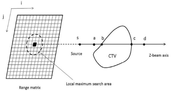
A schematic illustration of the method used to calculate the range matrix and relevant margin of a ray. Radiological path length is calculated per ray, and a kernel is applied to replace the radiological path length of a given ray with the local maximum within a distance (the lateral setup error and organ motion) of the range matrix. 3.5% of the assigned path length is used to convert to physical depth to form a margin (distal , proximal ).
Both the DMi, j and PMi, j for a given ray were found by taking 3.5% of the radiological path length that was calculated using Eqs. (2) and (3).
| (4) |
| (5) |
All the rays and their corresponding PMs and DMs were calculated accordingly. All margins were measured in unit of water-equivalent thickness first. This step is illustrated in Fig. 2 (c).
Fig. 2.
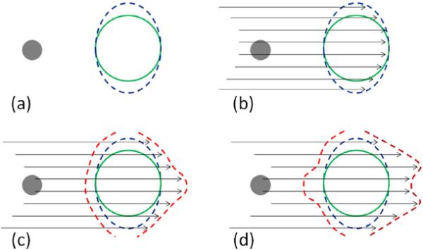
An illustration of the four essential steps in creating the bsPTV (red contour) from a CTV (green contour) with a dense object (grey sphere) along the beam path. (a) The CTV is expanded laterally away from the beam axis using the expected motion margin (IM) and setup margin (SM). (b) From a given beam angle, ray tracing is performed to calculate the radiological path length of each ray from the source to the both distal and proximal surface of the laterally expanded CTV (blue contour). (c) The fraction of the total radiological range calculated in previous step is used to the distal margins per ray. (d) Correction for interplay effect of setup and range error is accounted by applying the correction kernel and the radiological path length margins are converted to physical depth margins.
Correction for tissue density misalignment
The margins described above has not considered the situation that the setup errors can also introduce radiological pathlength variations due to misalignment of heterogeneous tissues in the beam path. In order to account for the misalignment of tissue heterogeneity, we replaced Di, j for a given ray with the maximum radiological path length (DMax(i, j)) found within a distance defined by the lateral setup error and organ motion perpendicular to the ray line: this is equivalent to applying a kernel to the range matrix that replace each index value (the radiological path length) by its local maximum. This maximum water-equivalent thickness is then used to compute DMi, j. Similarly, the same operation was applied to proximal side by replacing Pi, j with the minimum (rather than the maximum) radiological path length (DMin(i, j)). After repeating this process for each ray line within the beam aperture, the new local distal and proximal margins are created, accounting for additional range uncertainties caused by setup errors and organ motion lateral to the beam direction.
Conversion to physical depth margin
The margins calculated above are defined in terms of water equivalent radiological path length. However, tissues near the CTV may be heterogeneous. In order to use the PTV concept and compare the isodose lines with the PTV volume directly, it becomes necessary to convert the water-equivalent margin into a geometric expansion of identical radiological path length (to provide the “iso-penetration” for the beam). Therefore, in the final step, we converted the water-equivalent bsPTV to a physical bsPTV with identical radiological path length using the local density information from the CT data. Thus, we expressed the resulting physical depth margins of a given ray line as follow (see Fig. 1):
| (6) |
| (7) |
where the points c and d (a and b for proximal) are the limits of the following integral:
| (8) |
| (9) |
Fig. 2 shows a step-by-step illustration of bsPTV formation using the method described here.
Validation study
In-house software implementation
Because existing treatment planning system could not produce the bsPTV, we implemented the calculation in standalone software written in Matlab (Mathworks, Natick, MA). The software takes DICOM CT images, structure set, and RT plan as input. The software allows the selections of a target (CTV), a beam angle, and various parameters related to setup errors and range uncertainties. The software will calculate and create the bsPTV as a DICOM RT structure contour, which can be imported back to the treatment planning system.
Phantom construction
A virtual CT phantom with a water-equivalent body, a CTV, and a high-density object was created. The CTV (50 Hounsfield unit [HU]; volume = 50.4 cm3) was placed at the center of the body of water-equivalent material (0 Hounsfield unit [HU]), and the high-density object (1800 HU; volume = 1.9 cm3) was placed approximately 5 cm upstream of the proximal surface of the CTV. The distance from the surface of the body to the center of the CTV was 14 cm.
Target volume definitions
The conventional PTV was constructed in order to compare the results with bsPTV. The PTV was derived from the CTV by following a geometric expansion as in the photon planning. An 8-mm margin was used to expand the CTV laterally in the beam's eye view to create the PTV. The 8-mm LM was chosen to ensure lateral dose conformity when we applied a setup error of up to 6 mm. DM and PM values of 8.5 mm and 7.5 mm, respectively, were calculated using the following equations:
| (10) |
| (11) |
The extra 3mm margins from the above equations are used to account for inaccuracies in dose calculation algorithm to handle large angle scatter and nuclear interactions in the proton beam as well as the inaccuracy in manufacturing compensators. Similarly, for the bsPTV, the same 8-mm LM was used to expand the CTV. The method described in the previous section was used to expand the CTV in the distal and proximal directions with a uniform setup error of 6 mm, which resulted in a non-uniform expansion of the CTV for both the distal and proximal surfaces.
Treatment planning and simulation
A treatment plan using a single field with a gantry angle of 270° (directed from the patient's right to his/her left) that passed through the high-density object was created using SFUD to give a uniform dose of 200 cGy to the PTV and likewise to the bsPTV. To compare the robustness of the plans based on the PTV and bsPTV, we applied the original treatment beam data to CT data sets under different combinations of errors and recalculated doses for each simulation. Setup error was simulated by shifting the entire CT data set from its original isocenter from 0 mm to 6 mm in increments of 2 mm perpendicular to the beam axis. Internal motion was simulated by moving the high-density object from 0 mm to 8 mm in increments of 2 mm with respect to the center of the CTV along the same direction of the body shift. Systematic proton range error was introduced into the simulation by increasing the HU values of the entire CT data set by 3% which is close to 2.1% of radiological range error in the soft tissue region. Different combinations of setup, motion, and range errors resulted in 40 unique dose distributions for each plan using the PTV and bsPTV.
RESULTS
The resultant bsPTV closely conformed to the PTV except for the area where the smearing operation had the greatest impact. The final bsPTV was slightly larger than the PTV owing to the “horn-like” expansion as shown in Fig. 2d. The measured volume of PTV and bsPTV were 126 cm3 and 161 cm3, respectively. Fig. 3 shows examples of the dose distributions for some of the conditions used in the PTV and bsPTV treatment plan comparisons. The left column shows the dose distribution of plans designed using the PTV, and the right column shows the bsPTV as described in the previous section. The top figures show the dose distribution under normal conditions and no setup or motion uncertainties, while the bottom figures show the dose distribution with CT data with 3% increase in the CT number and a 6-mm setup error and an 8 mm shift of the high-density object. Under normal conditions, the prescribed dose for the CTV was uniform throughout the volumes for both plan using the PTV and bsPTV.
Fig. 3.
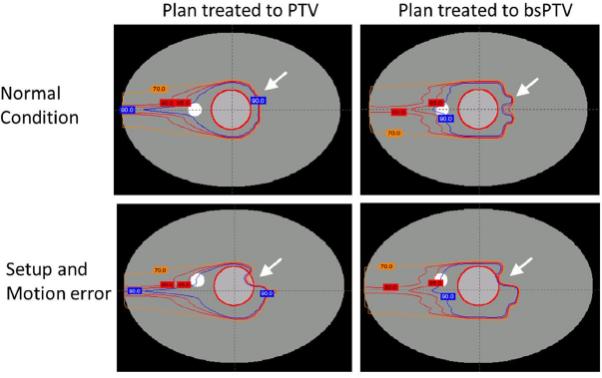
Dose distributions when conforming dose to the CTV (inner circular contour) using plans based on the PTV and bsPTV. From outside to inside, the isodose lines of 90% (blue), 85% and 80% (red), and 70% (orange) are shown.
The minimum percent dose which is the minimum dose found within the ROI as a percentage of the prescribed dose was used to measure the performance of both PTV and bsPTV. For the plans using the PTV as the primary target, with the normal CT data set, the minimum percent dose coverage to the CTV dropped from 99% to 95% with a 6-mm setup error, to 94% with an 8-mm motion, and to 88% when both setup error and motion were applied (see Fig. 4a). The margins calculated for both the proximal and distal edges using Eqs. (10) and (11) were meant to account for the systematic range calculation error. To take this systematic range calculation error into consideration in conjunction with both setup error and motion, we increased the CT number by 3% of its original value and recalculated dose distributions using the original beam data. When using this modified CT data set, the minimum percent dose coverage to the CTV dropped from 99% to 92% with a 6-mm setup error, to 83% with an 8-mm motion, and to 67% when both setup error and motion were applied (see Fig. 4b). Despite using PTV margins that exceeded the simulated uncertainties, dose coverage to the CTV was not maintained owing to the misplaced high-density object. Most of the under dosage occurred at the distal surface of the CTV along the lines passing through the high-density object.
Fig. 4.
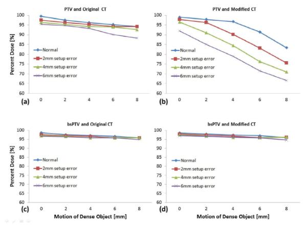
The minimum percentage of prescribed dose to the CTV for (a) plans using PTV simulated with original CT data, (b) plans using PTV with 3% up-scaled CT data, (c) plans using the bsPTV with original CT data, and (d) plans using bsPTV with 3% up-scaled CT data. The lines represent different setup errors ranging from 0 mm to 6 mm while the horizontal axis represents increasing motion errors of the dense object from 0 mm to 8 mm.
The right-hand images in Fig. 3 show the dose distributions for plans that were designed using the bsPTV, which was derived from the CTV using an 8-mm LM plus PM and DM calculated as described above. For this plan, using the normal CT data set, the minimum percent dose coverage to the CTV dropped from 99% to 95% when both 6 mm of setup error and 8 mm of motion were introduced (see Fig. 4c). Unlike the plans using the PTV, plans using the bsPTV showed little change in the minimum dose coverage to the CTV when using the modified CT data set. Under conditions of the largest simulated treatment uncertainty using the modified CT data, the dose coverage of the CTV dropped to 94% (see Fig. 4d). The range calculation error introduced by scaling up the CT numbers by 3% did not affect the dose coverage to the CTV when using the bsPTV as the primary target volume.
DISCUSSION
In this paper, we described a method of expanding the CTV treatment margins for planning purpose to account for the unique treatment delivery uncertainties encountered in proton radiotherapy. The results of the simulation study support the appropriateness of using bsPTV to calculate adequate margins to guarantee dose to CTV coverage for charged particle therapy. While the concept of employing beam-specific PTV is not new to the proton community, at the time of writing, its systematic design method has not been discussed in the literature. Previous studies have shown that the magnitude of required target margins depends on the beam's direction in proton therapy (7, 8, 16, 22) but specific designing methods to create such bsPTV have not been published in open literature. Thus, the current study fills an important gap in the goal of creating robust and yet practical target volumes.
Conventional PTV vs. bsPTV
The fundamental difference between the bsPTV design we have described in this paper and the conventional PTV is that the bsPTV method creates DMs and PMs that are varied along different rays according to their radiological path lengths. Furthermore, the bsPTV adds extra margins to account for possible range errors due to the misalignments of heterogeneous tissues traditionally done by compensator smearing. In addition, the final bsPTV takes into account local density variations of anatomical objects in the patient. The resulting shape of the bsPTV is highly dependent on the local tissue density near the CTV. In Fig. 5 we demonstrated the beam angle dependent characteristics of bsPTVs for one prostate and one thoracic case. It can be seen that bsPTV varies at different angles and depends strongly on local tissue densities surrounding the CTV. In the case of a homogeneous medium, the bsPTV should be similar to that of the conventional PTV, provided the PTV expansion is along the beam direction. In general, the size of the bsPTV will increase with increasing radiological path length to the target, setup error and the range of organ motion.
Fig. 5.
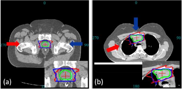
The CTV (green contour) is used to derive two bsPTVs (red and blue contours) under same specification (setup and range error) at different angles. (a) For prostate site, both bsPTV shows characteristic horn like distal shape to account for the misalignment of highly dense femur and femoral head. (b) For thoracic site, the two bsPTVs are significantly different in its shape and volume due to the difference in tissue density along their beam paths.
bsPTV for plan evaluation
Although the focus of this study was the utility of bsPTV as a robust proton planning tool, it is worth mentioning that defining the bsPTV may also be useful in plan evaluation. In conventional photon therapy, the dose-volume histogram (DVH) of the PTV is compared to the DVH of the CTV in order to judge the robustness of a given plan. This comparison assumes the PTV is large enough to contain the CTV of uncertain position during the course of treatments. Therefore, the DVH of the PTV is typically seen as the worst-case representation of CTV coverage in photon therapy. In proton therapy, however, such an interpretation of the DVH of the PTV does not work well because of the sensitivity of proton dose distribution to tissue heterogeneity and setup error. Currently there is no readily accepted method to evaluate a proton plan other than performing multiple dose calculations with simulated isocenter shifts. In Fig. 6, the DVH of the PTV and the DVH of the bsPTV under original conditions from our phantom study are shown separately along with all the DVHs of the CTV under the different simulation conditions. The arrow on Fig. 6a points to the area where some of the DVH curves reflect much worse coverage of the CTV than of the PTV itself, indicating that the DVH of the PTV does not necessarily represent the worse-case scenario for CTV coverage despite the fact that the PTV is derived by adding margins to the CTV that exceed the simulated geometrical uncertainty. In contrast, the DVH of the bsPTV curve conforms closely to the DVH curves of the CTV in this area, indicating that the coverage to the bsPTV closely represents the worst-case coverage for the CTV. Thus, it should be possible to use the difference in coverage between the bsPTV and CTV as a heuristic technique for evaluating the robustness of the proton treatment plan.
Fig. 6.
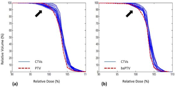
The DVHs of the CTV (blue lines) under simulated setup error and motion. (a) Plan using PTV, also shown here is DVH of PTV (red dotted line). (b) Plan using bsPTV, also shown here is DVH of bsPTV itself (red dotted line).
Limitation of the bsPTV in multi-field plans
The fundamental assumption used to derive the method of generating the bsPTV is that a uniform homogeneous dose is delivered to the volume being defined. When multiple beams are used and each beam is used to deliver uniform dose to the target, the bsPTV should be evaluated for each individual beam. It will be difficult to assess the overall target coverage because the interrelationship of different bsPTVs is difficult to combine into one PTV. The method presented in this paper will not be applicable to multi-beam, simultaneously optimized proton plan, such as the intensity- and energy-modulated proton therapy (IMPT) (23).
CONCLUSION
We investigated a practical method to create beam-specific PTV (bsPTV) for treatment planning and evaluation of proton beams. In current practice, scanning beam proton therapy using single-field optimization lacks a well-defined way of dealing with treatment uncertainties. The bsPTV takes into account both setup errors and range calculation uncertainties for the specific beam angle. The bsPTV can be used to directly design and evaluate a proton treatment plan similar to the geometric PTV concept used in the photon treatment planning. We demonstrated that the conventional (geometry-based) PTV concept in photon therapy failed to guarantee the prescribed dose coverage of the target in proton therapy because the dose distribution of protons is influenced by tissue heterogeneity along the beam's path. We demonstrated that the proton plan designed based on bsPTV concept provided better target coverage in the presence of setup error and range uncertainties.
Acknowledgments
Grant and financial support: This project is supported by P01CA021239 from the National Cancer Institute. The content is solely the responsibility of the authors and does not necessarily represent the official views of the National Cancer Institute or the National Institutes of Health.
Footnotes
Publisher's Disclaimer: This is a PDF file of an unedited manuscript that has been accepted for publication. As a service to our customers we are providing this early version of the manuscript. The manuscript will undergo copyediting, typesetting, and review of the resulting proof before it is published in its final citable form. Please note that during the production process errors may be discovered which could affect the content, and all legal disclaimers that apply to the journal pertain.
Conflict of Interest: None.
REFERENCES
- 1.International Commission on Radiation Units and Measurements . Stopping powers and ranges for protons and alpha particles ICRU Report 49. ICRU; Bethesda MD: 1993. [Google Scholar]
- 2.International Commission on Radiation Units and Measurements . Prescribing, Recording, and Reporting Photon Beam Therapy ICRU Report 62 (Supplement to ICRU Report 50) ICRU; Bethesda MD: 1999. [Google Scholar]
- 3.International Commission on Radiation Units and Measurement . Prescribing, Recording and Reporting Electron Beam Therapy ICRU Report 71. Oxford University Press; Oxford: 2004. [Google Scholar]
- 4.Stroom JC, De Boer HCJ, Huizenga H, et al. Inclusion of geometrical uncertainties in radiotherapy treatment planning by means of coverage probability. Int J Radiat Oncol Biol Phys. 1999;43(4):905–919. doi: 10.1016/s0360-3016(98)00468-4. [DOI] [PubMed] [Google Scholar]
- 5.Van Herk M, Remeijer P, Rasch C, et al. The probability of correct target dosage: Dose-population histograms for deriving treatment margins in radiotherapy. Int J Radiat Oncol Biol Phys. 2000;47(4):1121–1135. doi: 10.1016/s0360-3016(00)00518-6. [DOI] [PubMed] [Google Scholar]
- 6.Cho BCJ, Van Herk M, Mijnheer BJ, et al. The effect of set-up uncertainties, contour changes, and tissue inhomogeneities on target dose-volume histograms. Med Phys. 2002;29(10):2305–2318. doi: 10.1118/1.1508800. [DOI] [PubMed] [Google Scholar]
- 7.Moyers MF, Miller DW, Bush DA, et al. Methodologies and tools for proton beam design for lung tumors. Int J Radiat Oncol Biol Phys. 2001;49(5):1429–1438. doi: 10.1016/s0360-3016(00)01555-8. [DOI] [PubMed] [Google Scholar]
- 8.Engelsman M, Kooy HM. Target volume dose considerations in proton beam treatment planning for lung tumors. Med Phys. 2005;32(12):3549–3557. doi: 10.1118/1.2126187. [DOI] [PubMed] [Google Scholar]
- 9.Lomax AJ. Intensity modulated proton therapy and its sensitivity to treatment uncertainties 2: The potential effects of inter-fraction and inter-field motions. Phys Med Biol. 2008;53(4):1043–1056. doi: 10.1088/0031-9155/53/4/015. [DOI] [PubMed] [Google Scholar]
- 10.Lomax AJ. Intensity modulated proton therapy and its sensitivity to treatment uncertainties 1: The potential effects of calculational uncertainties. Phys Med Biol. 2008;53(4):1027–1042. doi: 10.1088/0031-9155/53/4/014. [DOI] [PubMed] [Google Scholar]
- 11.Meyer J, Bluett J, Amos R, et al. Spot scanning proton beam therapy for prostate cancer: Treatment planning technique and analysis of consequences of rotational and translational alignment errors. Int J Radiat Oncol Biol Phys. 2010;78(2):428–434. doi: 10.1016/j.ijrobp.2009.07.1696. [DOI] [PubMed] [Google Scholar]
- 12.Yoon M, Shin D, Kwak J, et al. Characteristics of movement-induced dose reduction in target volume: A comparison between photon and proton beam treatment. Medical Dosimetry. 2009;34(3):191–201. doi: 10.1016/j.meddos.2008.08.004. [DOI] [PubMed] [Google Scholar]
- 13.Trofimov A, Nguyen PL, Coen JJ, et al. Radiotherapy treatment of early-stage prostate cancer with IMRT and protons: A treatment planning comparison. Int J Radiat Oncol Biol Phys. 2007;69(2):444–453. doi: 10.1016/j.ijrobp.2007.03.018. [DOI] [PMC free article] [PubMed] [Google Scholar]
- 14.Widesott L, Pierelli A, Fiorino C, et al. Intensity-modulated proton therapy versus helical tomotherapy in nasopharynx cancer: Planning comparison and NTCP evaluation. Int J Radiat Oncol Biol Phys. 2008;72(2):589–596. doi: 10.1016/j.ijrobp.2008.05.065. [DOI] [PubMed] [Google Scholar]
- 15.Zhang X, Zhao K-, Guerrero TM, et al. Four-dimensional computed tomography-based treatment planning for intensity-modulated radiation therapy and proton therapy for distal esophageal cancer. Int J Radiat Oncol Biol Phys. 2008;72(1):278–287. doi: 10.1016/j.ijrobp.2008.05.014. [DOI] [PMC free article] [PubMed] [Google Scholar]
- 16.Rietzel E, Bert C, et al. Respiratory motion management in particle therapy. Med Phys. 2010;37(2):449–160. doi: 10.1118/1.3250856. [DOI] [PubMed] [Google Scholar]
- 17.Urie M, Goitein M, Wagner M. Compensating for heterogeneities in proton radiation therapy. Plasma Sources Sci Technol. 1984;29(5):553–66. doi: 10.1088/0031-9155/29/5/008. [DOI] [PubMed] [Google Scholar]
- 18.Schaffner B, Pedroni E. The precision of proton range calculations in proton radiotherapy treatment planning: experimental verification of the relation between CT-HU and proton stopping power. Phys Med Biol. 1998;43(6):1579–1592. doi: 10.1088/0031-9155/43/6/016. [DOI] [PubMed] [Google Scholar]
- 19.Geithner O, Andreo P, Sobolevsky N, et al. Calculation of stopping power ratios for carbon ion dosimetry. Phys Med Biol. 2006;51(9):2279–2292. doi: 10.1088/0031-9155/51/9/012. [DOI] [PubMed] [Google Scholar]
- 20.Moyers MF, Sardesai M, Sun S, et al. Ion stopping powers and CT numbers. Medical Dosimetry. 2010;35(3):179–194. doi: 10.1016/j.meddos.2009.05.004. [DOI] [PubMed] [Google Scholar]
- 21.Schneider U, Pedroni E, Lomax A. The calibration of CT Hounsfield units for radiotherapy treatment planning. Phys. Med. Biol. 1996;41(1):111–124. doi: 10.1088/0031-9155/41/1/009. [DOI] [PubMed] [Google Scholar]
- 22.Yoon M, Kim D, Shin DH, et al. Inter- and intrafractional movement-induced dose reduction of prostate target volume in proton beam treatment. Int J Radiat Oncol Biol Phys. 2008;71(4):1091–1102. doi: 10.1016/j.ijrobp.2007.11.031. [DOI] [PubMed] [Google Scholar]
- 23.Lomax A. Intensity modulation methods for proton radiotherapy. Phys Med Biol. 1999;44(1):185–205. doi: 10.1088/0031-9155/44/1/014. [DOI] [PubMed] [Google Scholar]


