Abstract
Background
Malignant melanoma has a good prognosis if treated early. Dermoscopy images of pigmented lesions are most commonly taken at × 10 magnification under lighting at a low angle of incidence while the skin is immersed in oil under a glass plate. Accurate skin lesion segmentation from the background skin is important because some of the features anticipated to be used for diagnosis deal with shape of the lesion and others deal with the color of the lesion compared with the color of the surrounding skin.
Methods
In this research, gradient vector flow (GVF) snakes are investigated to find the border of skin lesions in dermoscopy images. An automatic initialization method is introduced to make the skin lesion border determination process fully automated.
Results
Skin lesion segmentation results are presented for 70 benign and 30 melanoma skin lesion images for the GVF-based method and a color histogram analysis technique. The average errors obtained by the GVF-based method are lower for both the benign and melanoma image sets than for the color histogram analysis technique based on comparison with manually segmented lesions determined by a dermatologist.
Conclusions
The experimental results for the GVF-based method demonstrate promise as an automated technique for skin lesion segmentation in dermoscopy images.
Keywords: image processing, dermoscopy, active contours, gradient vector flow snakes, melanoma, boundary
Dermoscopy, otherwise known as skin-surface microscopy or dermatoscopy was originally introduced in 1921 (1) and reintroduced in 1987 (2). One common form of dermoscopy integrates oil immersion under glass with standard × 10 magnifying optics and incident surface lighting permit in vivo visualization of certain features of pigmented melanocytic neoplasms that cannot be observed by visual inspection. Dermoscopy using various rule- or feature-based schemes improves pigmented lesion diagnostic accuracy over the accuracy obtained without this aid for those dermatologists trained in the technique (3–8). Accurate segmentation of the lesion from the background skin is important for computer-assisted diagnostic techniques, both for the determination of lesion shape and lesion color, compared with the color of the surrounding skin (9).
In this paper, a method of automatic lesion boundary detection using gradient vector flow (GVF) snakes is presented. Snakes can be defined as curves within an image domain that can move under the influence of internal forces defined within the curve, from features such as smoothness, and external forces computed from the image data (10). Snake algorithms are often sensitive to initialization for effective object segmentation. Initial points for a snake algorithm can be selected by an operator or automatically determined. For this research, an automatic initialization method is used to select an initial set of skin lesion border points for the dermoscopy image data set examined.
The remainder of this paper is organized as follows. In the following section, an overview of traditional snake algorithms is presented, along with limitations of traditional snakes in the domain of pigmented images. In the third section, GVF snakes are presented. In the fourth section, the application of GVF snakes for skin lesion border determination in dermoscopy images is given. The automatic initialization method and the two-step operation of GVF snakes are described. In the fifth section, experimental results and discussion are presented comparing the GVF snake algorithm and its comparison with the histogram analysis technique developed by Pagadala (11). Finally, conclusions from this research are provided.
Overview of snake algorithms
The concept of deformable active contours, or snakes, was introduced by Kass et al. (12). The behavior of snakes is governed by minimizing their energy function (12)
where s∈[0, 1] and υ(s) = (x(s),y(s)) represents the position of the snake parametrically. Einternal is the internal energy of the snake, which specifies the tension or smoothness of the contour. Eimage is the image energy providing the external forces to the snake that cause the snake to move toward object boundaries as the energy is minimized. υ(s) is a set of coordinates to form a snake contour. A more complete overview of active contours, or snakes, can be found in (10, 13).
Weaknesses of conventional snakes
There are several weaknesses with conventional snake algorithms applied to boundary segmentation. First, the initial contour must be close to the actual object boundary because of the small capture range of the image gradient and the presence of artifacts in skin. Conventional snakes lack the larger capture range of several new methods (13, 14). Second, the weights of energies can affect the snake's behavior and performance of the deformation process. The weight constants are given by the operator in most of the applications. However, it is difficult but not impossible to modify conventional snakes with an adaptive system to change parameters automatically using data from the image during the deformation process and achieve better results. The third weakness of traditional snakes is the difficulty with expanding into boundary concavities (15, 16).
GVF snakes
GVF snakes use a new class of external forces. GVF fields are computed through a diffusion process (13), similar in spirit to the distance potential forces of Cohen and Cohen (14). Particular advantages of the GVF snake over a traditional snake are its insensitivity to initialization and its ability to move into boundary concavities (13). The initialization of the snake can be performed inside, outside, or across the object boundary. The GVF snake also has a larger capture range, due in part to a diffused image gradient (13). The GVF force can be computed from the Helmholtz theorem (17) as
where υ=υ(x, y) is the GVF field (13).
A parametric curve solving the above dynamic equation is called a GVF snake (13). The solution to this equation is obtained in the same manner as in a traditional snake algorithm by discretization and iteration. An edge map f(x, y), derived from an intensity image f(x, y), is determined. See (13, 18) for a more detailed mathematical description of GVF snakes.
Although GVF snakes may improve initialization, capture range, and progressing into concavities, images can create different types of problems during implementation. Some preprocessing techniques can be used to avoid these problems when applying the algorithm as we did for our dermoscopy image set.
Skin lesion boundary determination algorithm
GVF snakes are applied in this research as part of an automated skin lesion border determination algorithm for dermoscopy images. A Matlab implementation for the basic GVF snake algorithm was obtained from (19), modified for this implementation, and converted to C11. The algorithm consists of preprocessing operations and a two-step GVF-based approach.
Preprocessing and initialization of snake points
Preprocessing of the dermoscopy images is performed in two steps, including automatic snake point initialization and skin lesion image preprocessing, to facilitate application of the GVF snake algorithm. The dermoscopy images can have significant artifacts such as hair, small air bubbles, and skin texture around the skin lesion. These artifacts may prevent the snake from converging to the real skin lesion boundary during the deformation process, resulting in incorrect borders. Because the gradient information of the image is diffused in the image domain by the GVF method, the capture range of artifacts in the image as well as the capture range of the skin lesion boundary have been increased. Consequently, there is the potential problem that the snake may converge and remain on a noise point during the deformation process, resulting in an incorrect border.
Two steps to overcome this problem are to initialize snake points close to the actual border and to decrease the noise level in the image. We found that Gaussian filtering decreased the image noise or artifact level in the image to allow the snake to ignore weak edges on the lesion border.
The following procedure was used to initialize the snake points relatively close to the actual lesion border. The luminance image (20) was determined from the dermoscopy RGB color image and used for preprocessing operations and for applying the GVF snake algorithm. In order to facilitate snake initialization, blurring of the skin lesion region was performed using a 15 × 15 Gaussian filter (21) (Gσ with σ=15), which functions as an averaging filter rather than a Gaussian filter, since the kernel size is relatively small for this value of σ. The blurred image is inverted and thresholded using the Otsu technique (22), a histogram-based approach that assumes Gaussian distributions for the background and foreground pixels, where a threshold T is the gray level that maximizes between-group variance. The Otsu threshold T (Fig. 3) is reduced by P gray levels to provide for under-segmentation of the skin lesion region, where P=10 was empirically determined for our dermoscopy image data set. Blob labeling (23) of all eight connected objects within the thresholded image was performed, and the largest blob was retained as the skin lesion region.
Fig. 3.
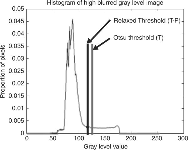
Histogram of negative of blurred image used for thresholding. The Otsu and relaxed thresholds obtained for this image are labeled.
Initial snake points were found along the edge of the skin lesion region (largest blob) using eight lines radiated at equal angles from the centroid of the lesion region. These points were expanded along the radial lines in approximately the normal direction, from the lesion region edge toward the image edge by a small constant to guarantee that the initial snake is formed outside the lesion border. The constant value of five pixels was empirically optimized for the application. Cubic spline interpolation was applied to the eight initial points to locate new snake points.
Application of GVF snake algorithm
After preprocessing and initialization of snake points, the gradient of the gray-level image and the corresponding GVF field of the gradient image were computed using Matlab. A two-step operation for the snake deformation process was used. The GVF field image was calculated by applying a high level of blurring to the gray level and gradient images, decreasing noise and artifacts such as hair and bubbles in the image domain that can prevent the snake from converging to the skin lesion border. A 6 × 6 Gaussian kernel (Gσ with σ=6) for the gray-level image and a 5 × 5 Gaussian kernel (Gσ with σ=5) for the gradient image, empirically determined, functioned as blurring parameters. In order to prevent the initial snake from deforming towards the image edge, the initial snake points were restricted to the central 8/9 W× 8/9 H of the W × H image. The Sobel operator (24) was used to generate the gradient images in this research.
During the deformation process in the first operation, a reduced number of iterations, 20, were used to get closer to the border without converging on the noise or artifacts around the skin lesion region. Linear interpolation (25) was used to add snake points during deformation if the Euclidean distance between two neighboring snake points became greater than one pixel.
After the first operation, the snake moves closer to the actual skin lesion border, with less likelihood that the snake will converge to noise points in the surrounding skin region. Therefore, the second operation used a small kernel on the gray level and the gradient images, a 2 × 2 Gaussian kernel (Gσ with σ=2) and a 4 × 4 Gaussian kernel (Gσ with σ = 3.5, respectively. The Gaussian kernels functioned as blurring filters for the luminance and gradient of luminance images. Filter parameters and the number of iterations used, 60, in the deformation process of the second iteration were empirically determined.
The final step of the border determination algorithm was to expand the border uniformly in all directions by N pixels. A line was constructed perpendicular to the line connecting two neighboring points. The snake point was expanded N pixels in an outward direction along this line. Based on experimentation with our dermoscopy image data set, N=9 was selected. This procedure was performed because the snakes tend to find the border at the maximum gradient, which lies somewhat inside the actual border location. A simple but effective solution for this problem is to expand the resultant border by some number of pixels in the normal direction.
Experiments performed
The GVF-based border determination algorithm was applied to a dermoscopy RGB image data set of 30 invasive malignant melanomas and 70 benign skin lesions. Images were full color 24 bit with typical resolutions of 1024 × 768 in jpeg format, obtained from the EDRA interactive Atlas of Dermoscopy (26). The benign skin lesions included dysplastic nevi, lentigines, and melanocytic nevi. None of the skin lesions included in the data set about the image boundaries. The resulting closed skin lesion borders are filled to obtain segmented skin lesions.
Baseline manually determined borders
For manual segmentation, points were selected along the skin lesion border. A cubic B-spline algorithm was used to connect the manually selected points to generate a closed curve lesion border. A dermatologist (Dr Stoecker) supervised all boundary determinations, providing the baseline for evaluation of the automated techniques. A second dermatologist (Dr Malters) found borders manually for comparison with the automated techniques.
Pagadala's automated technique
A fully automated histogram-based thresholding technique developed by Pagadala (11) was used for comparison with the GVF-based approach. For this approach, a histogram was made for each of the three color planes for each lesion. For each histogram, the local maxima (peaks) are determined initially with 10 bins. If only one local maximum can be obtained, the number of bins in the histogram was increased and the local maxima were again determined. Once the local maxima were found, the minimum between the two largest local maxima is found.
A brightness value equal to one-third the distance between the histogram peaks when added to the minimum brightness value gave a more useful threshold than the minimum brightness value for separating the skin lesion from the surrounding skin. After the threshold was obtained for each color plane, the color value for each pixel in the image was replaced with the minimum color value of the pixels in its 5 × 5 neighborhood. Then, thresholding was performed in each of the color planes. An OR function was applied to the individual thresholded color planes to generate a preliminary segmented lesion. The final segmented skin lesion was obtained based on smoothing the binary ORed image by an iterative median filter procedure that used decreasing filter sizes of 9 × 9, 7 × 7, 5 × 5, and 3 × 3.
Approach for evaluating automatically segmented skin lesions
Using baseline manually segmented skin lesions from a dermatologist (Dr Stoecker), the segmented lesions obtained from the GVF-based algorithm, Pagadala's color histogram threshold technique, and manually segmented lesions from a second dermatologist (Dr Malters) were compared based on the grading system developed by Umbaugh et al. (27). Let M represent the area of the manually segmented skin lesion for the same image. Let A denote the automatically segmented lesion and XOR the exclusive-OR operation. Then, the percentage border error (B) is given by .
Experimental results and discussion
Image example
An image example is presented for the GVF-based algorithm for skin lesion segmentation for a dysplastic compound nevus, a benign lesion, shown in Fig. 1. Figure 2 shows the negative of the blurred gray-level image obtained from the 15 × 15 Gaussian kernel (Gσ with σ=15). This image is used for the snake point initialization process. Figure 3 shows the histogram of the blurred image used for threshold determination to obtain the skin lesion region, showing the Otsu threshold T and the relaxed threshold T–P. Figure 4 presents the segmented skin lesion region, where the largest blob has been retained as the skin lesion region. Figure 5 shows the initial snake after applying the automated snake initialization algorithm with interpolation. Figure 6 provides the resulting deformed snake after the first operation of the GVF snake algorithm for 20 iterations. Figure 7 presents the resulting deformed snake after the second operation of the GVF snake algorithm for 60 iterations. Figure 8 shows the final skin lesion border after expanding the deformed snake by nine pixels in the normal direction from the second operation of the GVF snake algorithm.
Fig. 1.
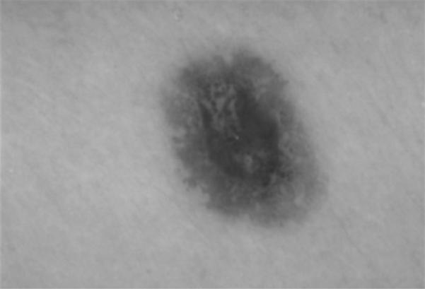
Dermoscopy image of a dysplastic compound nevus, a benign pigmented skin lesion.
Fig. 2.
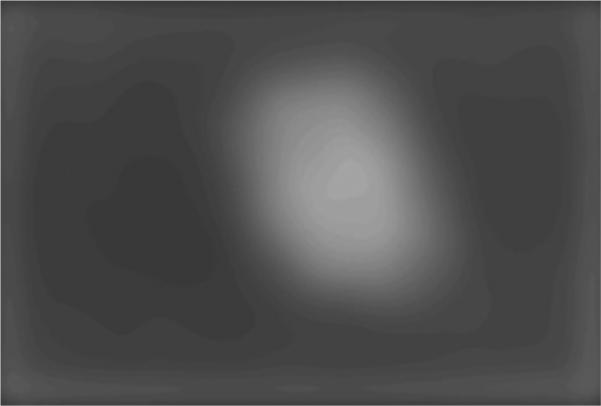
Negative of blurred gray-level image used for snake initialization.
Fig. 4.
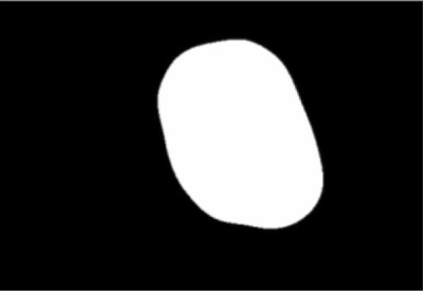
Skin lesion region obtained after thresholding, blob labeling, and retaining the largest blob.
Fig. 5.
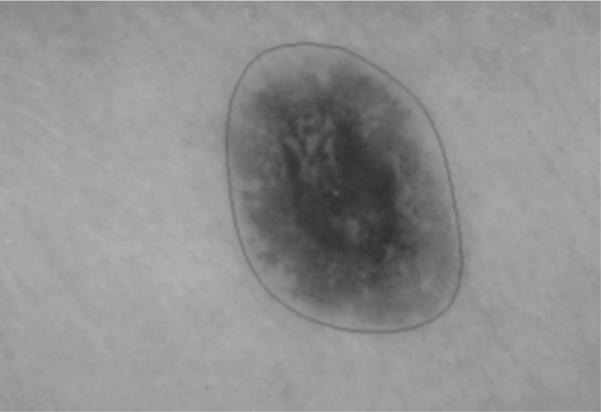
Initial gradient vector flow snake boundary after initialization algorithm and cubic spline interpolation.
Fig. 6.
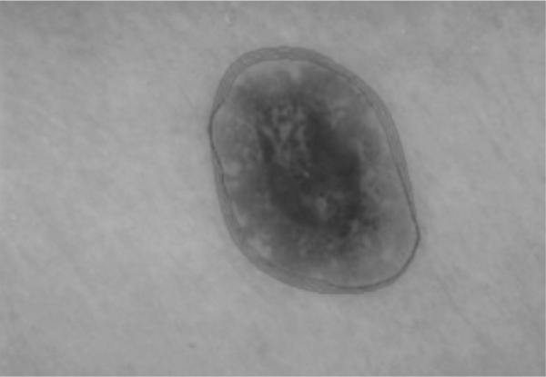
Output of gradient vector flow snake deformation process during the first operation after 20 iterations. Snake boundaries are shown for every fifth iteration.
Fig. 7.
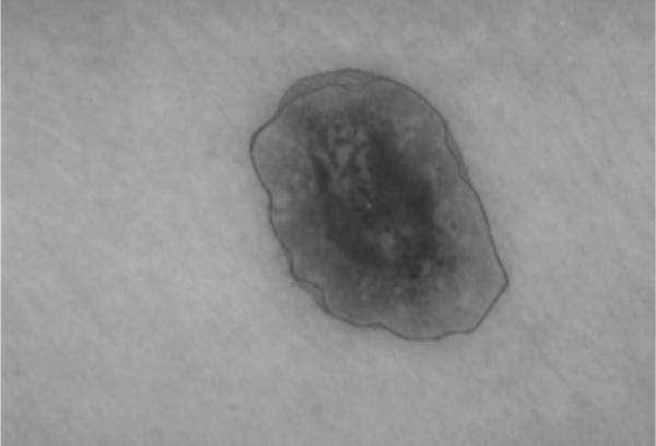
Output of gradient vector flow snake deformation process during the second operation after 60 iterations. Snake boundaries are shown for every fifth iteration.
Fig. 8.
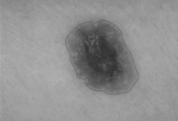
Final skin lesion border after expanding gradient vector flow snake boundary from Figure 7 based on the normal direction along the snake boundary.
Border error results
The GVF-based algorithm, the color histogram thresholding approach (Pagadala's method), and the manual method were applied to the entire data set. Using manually determined borders from a dermatologist as a baseline, the border error/difference (B) was computed for each skin lesion for the automated methods and the comparison borders found by a second dermatologist. Tables 1 and 2 contain the mean, standard deviation, and median border errors/differences for the three approaches for the benign and melanoma images, respectively, in the data set. Figure 9 presents a benign lesion example of the borders generated using the manual and automated techniques, with the borders superimposed on the lesion. The white border was the baseline border manually determined by a dermatologist. Note that the lesion shown in Fig. 9 corresponds to image number 48 in Table 1.
TABLE 1.
Percentage border error/difference results for benign lesions for the gradient vector flow (GVF)-based method, Pagadala's technique, and manual borders from the second dermatologist
| Image no | GVF method | Pagadala's technique | Borders from second dermatologist |
|---|---|---|---|
| 1 | 27.25 | 15.89 | 6.78 |
| 2 | 14.66 | 27.67 | 5.48 |
| 3 | 17.64 | 13.19 | 4.92 |
| 4 | 8.57 | 18.01 | 4.52 |
| 5 | 15.52 | 6.69 | 8.69 |
| 6 | 7.13 | 5.89 | 7.22 |
| 7 | 19.29 | 6.86 | 6.78 |
| 8 | 6.63 | 5.17 | 5.48 |
| 9 | 5.74 | 11.25 | 4.92 |
| 10 | 17.46 | 9.76 | 4.52 |
| 11 | 11.28 | 21.23 | 8.69 |
| 12 | 16.88 | 9.52 | 7.22 |
| 13 | 10.09 | 9.57 | 14.14 |
| 14 | 15.71 | 24.51 | 10.59 |
| 15 | 22.40 | 31.69 | 7.37 |
| 16 | 11.34 | 15.63 | 10.75 |
| 17 | 13.30 | 28.54 | 7.71 |
| 18 | 11.20 | 25.69 | 15.62 |
| 19 | 9.08 | 14.78 | 4.86 |
| 20 | 20.45 | 10.09 | 6.88 |
| 21 | 8.29 | 14.58 | 8.83 |
| 22 | 17.03 | 13.48 | 10.85 |
| 23 | 14.17 | 16.68 | 19.44 |
| 24 | 13.08 | 507.10 | 11.83 |
| 25 | 16.89 | 8.03 | 5.42 |
| 26 | 23.01 | 32.24 | 8.69 |
| 27 | 13.07 | 16.58 | 9.30 |
| 28 | 13.81 | 11.50 | 12.66 |
| 29 | 12.87 | 10.46 | 7.84 |
| 30 | 22.25 | 6.23 | 18.11 |
| 31 | 12.36 | 2.19 | 6.93 |
| 32 | 18.19 | 4.93 | 6.38 |
| 33 | 23.17 | 27.10 | 10.20 |
| 34 | 17.78 | 16.83 | 4.14 |
| 35 | 20.60 | 6.91 | 5.37 |
| 36 | 11.56 | 16.11 | 5.33 |
| 37 | 15.86 | 6.78 | 4.66 |
| 38 | 9.68 | 9.78 | 10.82 |
| 39 | 9.41 | 16.82 | 10.94 |
| 40 | 8.13 | 7.38 | 6.98 |
| 41 | 7.42 | 9.56 | 4.77 |
| 42 | 8.81 | 17.79 | 6.07 |
| 43 | 24.33 | 7.12 | 10.23 |
| 44 | 8.58 | 12.65 | 7.49 |
| 45 | 11.73 | 6.35 | 4.06 |
| 46 | 20.94 | 11.89 | 10.42 |
| 47 | 14.55 | 5.31 | 11.63 |
| 48 | 14.27 | 12.85 | 23.92 |
| 49 | 9.02 | 10.33 | 11.48 |
| 50 | 12.13 | 11.65 | 7.53 |
| 51 | 8.45 | 5.57 | 6.49 |
| 52 | 8.97 | 6.47 | 6.64 |
| 53 | 9.31 | 9.53 | 4.67 |
| 54 | 11.55 | 7.74 | 3.28 |
| 55 | 9.23 | 4.45 | 7.58 |
| 56 | 11.52 | 17.23 | 5.76 |
| 57 | 11.22 | 7.89 | 7.32 |
| 58 | 31.70 | 5.73 | 5.13 |
| 59 | 6.99 | 9.37 | 9.31 |
| 60 | 10.41 | 8.43 | 9.17 |
| 61 | 12.31 | 26.61 | 11.13 |
| 62 | 10.33 | 8.42 | 8.18 |
| 63 | 7.99 | 31.49 | 12.12 |
| 64 | 9.26 | 12.41 | 11.27 |
| 65 | 16.62 | 12.77 | 9.17 |
| 66 | 13.66 | 6.10 | 6.36 |
| 67 | 7.91 | 5.33 | 8.30 |
| 68 | 11.37 | 10.07 | 7.77 |
| 69 | 12.32 | 7.57 | 8.82 |
| 70 | 27.97 | 18.68 | 10.90 |
| Mean | 13.77 | 19.87 | 8.71 |
| SD | 5.61 | 59.53 | 3.78 |
| Median | 12.32 | 10.40 | 7.80 |
Average, SD, and median border errors/differences are provided for each approach. `Errors' are arbitrarily computed with respect to borders determined by the first dermatologist. GVF, gradient vector flow.
TABLE 2.
Percentage border error/difference for melanoma images for the gradient vector flow (GVF)-based method, Pagadala's technique, and manual borders from the second dermatologist
| Image no | GVF-based method | Pagadala's technique | Borders from second dermatologist |
|---|---|---|---|
| 1 | 13.90 | 6.22 | 17.36 |
| 2 | 12.10 | 13.20 | 6.15 |
| 3 | 16.69 | 7.85 | 5.89 |
| 4 | 22.32 | 73.65 | 6.04 |
| 5 | 15.03 | 22.55 | 4.85 |
| 6 | 21.37 | 7.35 | 6.14 |
| 7 | 27.09 | 804.48 | 18.37 |
| 8 | 18.41 | 32.16 | 10.56 |
| 9 | 14.17 | 21.66 | 11.33 |
| 10 | 15.23 | 21.26 | 9.93 |
| 11 | 14.99 | 10.96 | 7.35 |
| 12 | 27.33 | 11.32 | 16.29 |
| 13 | 21.38 | 8.99 | 4.80 |
| 14 | 16.17 | 23.80 | 6.99 |
| 15 | 19.61 | 20.93 | 13.38 |
| 16 | 18.32 | 14.30 | 10.08 |
| 17 | 21.08 | 29.48 | 8.21 |
| 18 | 36.03 | 23.50 | 7.39 |
| 19 | 22.82 | 16.37 | 3.33 |
| 20 | 11.69 | 23.25 | 7.87 |
| 21 | 31.12 | 251.36 | 5.48 |
| 22 | 28.41 | 31.26 | 4.23 |
| 23 | 20.34 | 35.38 | 6.54 |
| 24 | 14.74 | 17.87 | 10.75 |
| 25 | 20.95 | 1053.72 | 4.87 |
| 26 | 11.08 | 22.32 | 5.55 |
| 27 | 15.84 | 101.94 | 2.35 |
| 28 | 5.04 | 4.69 | 6.57 |
| 29 | 10.84 | 5.95 | 6.33 |
| 30 | 48.84 | 40.87 | 9.00 |
| Mean | 19.76 | 91.96 | 8.13 |
| SD | 8.60 | 234.46 | 3.99 |
| Median | 18.37 | 21.99 | 6.77 |
Mean, SD, and median results are provided for each approach. `Errors' are arbitrarily computed with respect to borders determined by the first dermatologist. GVF, gradient vector flow.
Fig. 9.
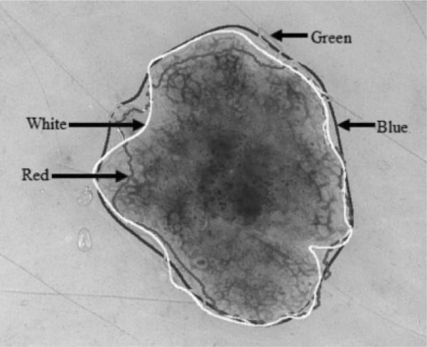
Benign lesion image example showing borders determined manually and automatically superimposed onto the lesion. Key for the borders shown: baseline dermatologist manual border (white), gradient vector flow-based algorithm (red), Pagadala's method (green), manual border by second dermatologist (blue). Note that both human-and computer-based methods have problems with the same areas where the border is hazy.
From Tables 1 and 2, it can be observed that the average errors obtained by GVF-based algorithm (13.77% for benign and 19.76% for melanoma) are lower for both the benign and melanoma image sets than for Pagadala's method. The average and median differences for the benign and melanoma image sets are lower for the manual borders from the second dermatologist than the automated methods. For the benign image set, the median difference for the second set of manual borders (7.80%) is similar to the error rates for the GVF-based algorithm (12.32%) and Pagadala's method (10.40%). For the melanoma image set, there is a greater disparity in the median differences for the second set of manually determined borders (6.77%) and the automated techniques (18.37% for the GVF-based algorithm and 21.99% for Pagadala's method). Greater border irregularity in melanoma lesions may have contributed to the greater disparity in lesion segmentation between the dermatologist-segmented lesions and the automated segmentation techniques. The median differences for the manually determined borders from the second dermatologist are similar for the melanoma (6.77%) and benign (7.80%) image sets with low standard deviations (3.99 for the melanoma image set and 3.78 for the benign image set), indicating consistency of the lesion segmentation results.
The higher standard deviation for Pagadala's method reflects the inconsistency of color segmentation. When images that gave an error of greater than 100% for Pagadala's method were not used in the image set, it was observed that the error levels of the two methods were similar. From Table 2, the mean and median percentage border errors are lower for the GVF-based method, 19.76% and 18.37%, respectively, than for Pagadala's technique, 91.96% and 21.99%, respectively. The color content difference between the benign and melanoma lesions may contribute to the disparity between the GVF-based method and Pagadala's technique. Table 3 shows the number of images with percentage border errors less than 10%, 20%, 30%, 40%, and 50% for the GVF-based method. From Table 3, 76 of the 100 images examined have percentage border errors of less than 20%, and 96 images have percentage border errors of less than 30%. The average (and median) variation for the GVF-based and Pagadala's methods is higher than the intraobserver variation observed by Guillod et al. (28) but is sufficiently small to allow accurate detection of lesion features.
TABLE 3.
Distribution of percentage border error results for all 100 benign and melanoma lesion images for the gradient vector flow (GVF)-based method
| Total number | Border error (%) |
||||
|---|---|---|---|---|---|
| ≤ 10 | ≤ 20 | ≤ 30 | ≤ 40 | ≤ 50 | |
| 100 | 18 | 76 | 96 | 99 | 100 |
Discussion
One of the main problems of GVF snakes applied to dermoscopy images is weak edges in some images. Because we have to perform some blurring to make the snake deform correctly, the weak edges become even weaker. Unfortunately, the noise or artifacts in the image can be stronger than these weak edges. Decreasing blurring results in the snake sticking onto noise or artifacts and produces the wrong border. Accordingly, we used several smoothing operators to provide a blurring effect to compensate for high-contrast noise or artifacts in our image data set. Note that Fig. 9 shows that borders diverge most, for both human and automatic methods, where edges are weakest.
The problem of automatic initialization has been addressed using the luminance image blurring and relaxed thresholding technique presented. Initialization and subsequent deformation can fail for lesions that extend to the edge of the image frame. In practice, some large lesions will extend to the image border.
Another weakness of the snake technique presented is that there are numerous parameters that we determined from our data set. The user can adjust parameters to conform to a user's visual standard of an acceptable skin lesion segmentation on an image-by-image basis. More testing should be carried out with different sets to determine whether our parameters are broadly applicable. For example, initial points could be expanded or contracted to obtain a more suitable set of initial snake points.
A two-step operation is used for the GVF snake application. This is done to prevent the snake from sticking on the noise or artifacts around the lesion during deformation. In the first operation, higher blurred grayscale and gradient images are used to calculate the GVF field. The snake points obtained from the first operation are used as input for the second operation. Less blurring is used during the second operation so that the snake can catch weaker edges. Figure 10 gives an image example where the initial snake border is located too far from the actual skin lesion border. The result is convergence to noise points and an incorrectly segmented skin lesion.
Fig. 10.
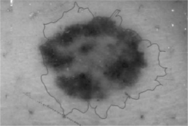
Example of the gradient vector flow snake algorithm converging to noise points around the skin lesion.
The results are obtained using a `reasonable' parameter set for 70 non-melanoma and 30 melanoma images. The results obtained were satisfactory for most of the images, but it was also observed that non-melanoma images gave better results. It was noted that the differences between dermatologists were similar for both benign and malignant lesions, and smaller than that between manual dermatologist borders and GVF borders. The reason for this result can be attributed to non-melanoma images having more regular boundaries than melanoma images. The eight initial snake points are determined in equal angular distances with respect to the centroid of the lesion, so the deformation process works better for images that do not have irregularities. The other reason is that melanoma images can have edges too weak to allow the snake to converge to them. We have found in other research that melanomas have widely varying gradients compared with benign lesions. Melanoma borders vary from very sharp to very fuzzy.
Finally, the snake algorithm presented in this research using the luminance image is representative of monochrome image segmentation techniques. Extending the snake algorithm to incorporate the RGB color planes is a future scope for this research.
Conclusion
In this research, a luminance image blurring approach was presented for automatic snake initialization, and the GVF snake algorithm was investigated to find the skin lesion borders of dermoscopy images automatically. The percentage border error obtained for the GVF-based method is more consistent for the benign and melanoma lesions examined than Pagadala's color thresholding-based approach. The experimental results show that 76 of 100 images have percentage border errors less than 20% and that 96 of 100 images have errors less than 30%. Overall, the experimental results for the GVF-based method demonstrate promise as an automated technique for skin lesion segmentation in dermoscopy images.
Acknowledgements
We gratefully acknowledge the guidance of Matthew G. Fleming, MD at the outset of this study and the assistance of Joseph M. Malters, MD in determining pigmented lesion borders.
References
- 1.Saphier J, Dermatoskopie D, Mitteilung I. Arch Dermatitis Syphillis. 1921;128:1–19. [Google Scholar]
- 2.Steiner A, Pehamberger H, Wolff K. Improvement of diagnostic accuracy in pigmented skin lesions by epiluminescent light microscopy. J Am Acad Dermatol. 1987;17:571–573. [PubMed] [Google Scholar]
- 3.Nachbar F, Stolz W, Merkle T, et al. The ABCD rule of dermatoscopy. J Am Acad Dermatol. 1994;30:551–559. doi: 10.1016/s0190-9622(94)70061-3. [DOI] [PubMed] [Google Scholar]
- 4.Binder M, Schwarz M, Winkler A, Steiner A, Kaider A, Wolff K, Pehamberger H. Epiluminescence microscopy. A useful tool for the diagnosis of pigmented skin lesions for formally trained dermatologists. Arch Dermatol. 1995;131:286–291. doi: 10.1001/archderm.131.3.286. [DOI] [PubMed] [Google Scholar]
- 5.Cristofolini M, Zumiani G, Bauer P, Cristofolini P, Boi S, Micciolo R. Dermatoscopy usefulness in the differential diagnosis of cutaneous pigmentary lesions. Melanoma Res. 1994;4:391–394. doi: 10.1097/00008390-199412000-00008. [DOI] [PubMed] [Google Scholar]
- 6.Steiner A, Pehamberger H, Wolff K. In vivo epiluminescence microscopy of pigmented skin lesions. II. Diagnosis of small pigmented skin lesions and early detection of malignant melanoma. J Am Acad Dermatol. 1987;17:584–589. doi: 10.1016/s0190-9622(87)70240-0. [DOI] [PubMed] [Google Scholar]
- 7.Pehamberger H, Binder M, Steiner A, Wolff K. In vivo epiluminescence microscopy: improvement of early diagnosis of melanoma. J Invest Dermatol. 1993;100:356S–362S. doi: 10.1111/1523-1747.ep12470285. [DOI] [PubMed] [Google Scholar]
- 8.Steiner A, Pehamberger H, Binder M, Wolff K. Pigmented Spitz nevi: improvement of diagnostic accuracy by epiluminescence microscopy. J Am Acad Dermatol. 1992;27:697–701. doi: 10.1016/0190-9622(92)70240-g. [DOI] [PubMed] [Google Scholar]
- 9.Zhang Z, Stoecker WV, Moss RH. Border detection on digitized skin tumor images. IEEE Trans Med Imaging. 2000;19:1128–1143. doi: 10.1109/42.896789. [DOI] [PMC free article] [PubMed] [Google Scholar]
- 10.Xu C, Pham DL, Prince JL. Medical image segmentation using deformable models. In: Fitzpatrick JM, Sonka M, editors. Handbook of medical imaging - Vol. 2: medical image processing and analysis. SPIE Press; Bellingham, WA, USA: 2000. pp. 129–174. [Google Scholar]
- 11.Pagadala P. MS Thesis. Department of Electrical Engineering, University of Missouri-Rolla; 1998. Tumor border detection in epiluminescence microscopy images. [Google Scholar]
- 12.Kass M, Witkin A, Terzopoulos D. Snakes: active contour models. Int J Comput Vision. 1998;1:321–331. [Google Scholar]
- 13.Chenyang Xu X, Prince JL. Snakes, shapes and gradient vector flow. IEEE Trans Image Process. 1998;7:359–369. doi: 10.1109/83.661186. [DOI] [PubMed] [Google Scholar]
- 14.Cohen LD, Cohen I. Finite-element methods for active counter models and balloons for 2-D and 3-D images. IEEE Trans Pattern Anal Mach Intell. 1993;15:1131–1147. [Google Scholar]
- 15.Davatzikos C, Prince JL. An active contour model for mapping the cortex. IEEE Trans Med Imaging. 1995;14:65–80. doi: 10.1109/42.370403. [DOI] [PubMed] [Google Scholar]
- 16.Abrantes AT, Marques JS. A class of constrained clustering algorithms for object boundary extraction. IEEE Trans Image Process. 1996;5:1507–1521. doi: 10.1109/83.541421. [DOI] [PubMed] [Google Scholar]
- 17.Morse PM, Fesbach H. Methods of theoretical physics. McGraw-Hill; New York: 1953. [Google Scholar]
- 18.Williams DJ, Shah M. A fast algorithm for active contours and curvature estimation. Comput Vision Graphics Image Process. Image Understanding. 1992;55:14–26. [Google Scholar]
- 19.Chenyang X, Prince JL. http://iacl.ece.jhu.edu/projects/gvf - gradient vector flow, April 2004.
- 20.Umbaugh SE. Computer vision and image processing: a practical approach using CVIP tools. Prentice-Hall, Inc.; Upper Saddle River, NJ: 1998. [Google Scholar]
- 21.Horn BKP. Robot vision, The MIT electrical engineering and computer science series. MIT Press; Cambridge, MA: 1986. [Google Scholar]
- 22.Otsu N. A threshold selection method from grey level histograms. IEEE Trans Systems, Man, Cybern. 1979;9:377–393. [Google Scholar]
- 23.Haralick RM, Shapiro LG. Computer and Robot Vision, Vol. I. Reading. Addison-Wesley; MA: 1992. [Google Scholar]
- 24.Sobel IE. PhD Thesis. Department of Electrical Engineering, Stanford University; 1970. Camera models and machine perception. [Google Scholar]
- 25.de Boor C. A practical guide to splines. Springer Verlag; Germany: 1978. [Google Scholar]
- 26.Argenziano G, Soyer HP, De Giorgi V, et al. Dermoscopy, an interactive atlas. EDRA Medical Publishing; Milan, Italy: 2000. [Google Scholar]
- 27.Umbaugh SE, Moss RH, Stoecker WV. Automatic color segmentation of images with application to identification of skin tumor borders. Comput Med Imaging Graph. 1992;16:227–235. doi: 10.1016/0895-6111(92)90077-m. [DOI] [PubMed] [Google Scholar]
- 28.Guillod J, Schmid-Saugeon P, Guggisberg D, Cerottini JP, Braun R, Krischer J, Saurat J-H, Kunt M. Validation of segmentation techniques for digital dermoscopy. Skin Res Technol. 2002;8:240–249. doi: 10.1034/j.1600-0846.2002.00334.x. [DOI] [PubMed] [Google Scholar]


