Abstract
Combining several methods for contact free micro-manipulation of small particles such as cells or micro-organisms provides the advantages of each method in a single setup. Optical tweezers, which employ focused laser beams, offer very precise and selective handling of single particles. On the other hand, acoustic trapping with wavelengths of about 1 mm allows the simultaneous trapping of many, comparatively large particles. With conventional approaches it is difficult to fully employ the strengths of each method due to the different experimental requirements. Here we present the combined optical and acoustic trapping of motile micro-organisms in a microfluidic environment, utilizing optical macro-tweezers, which offer a large field of view and working distance of several millimeters and therefore match the typical range of acoustic trapping. We characterize the acoustic trapping forces with the help of optically trapped particles and present several applications of the combined optical and acoustic trapping, such as manipulation of large (75 μm) particles and active particle sorting.
OCIS codes: (140.7010) Laser trapping, (170.4520) Optical confinement and manipulation, (350.4855) Optical tweezers or optical manipulation, (110.7170) Ultrasound
1. Introduction
Contact free trapping and micro-manipulation of small particles like cells or micro-organisms is a demanding task with many applications in physics, in analytical chemistry and in the life sciences. Many different methods have been realized that rely on a variety of approaches how to create the necessary forces, such as optical radiation forces, electric forces (dielectrophoresis), magnetic forces (magnetic tweezers) or mechanical forces generated by sound waves (for reviews see [1, 2, 3, 4, 5, 6]). Each method has its own peculiarities that make it the best choice for some specific application, but none of these methods can claim to fulfill all the requirements one might expect from an ideal implementation. Combining several methods that complement one another within a single setup offers new possibilities, if the drawbacks of one method can be compensated by the strengths of another.
In this paper we present the simultaneous implementation of acoustic and optical trapping of living micro-organisms within a microfluidic environment. Both trapping methods are similar in the sense that they rely on radiation forces exerted by optical or acoustic fields, respectively. However, since the wavelengths of the underlying radiation fields are quite different – about 1 μm for light and about 1 mm for ultrasound – the properties of the two methods are quite different. Optical trapping uses focused laser beams and offers a very precise and flexible way of handling individual small particles, but the comparatively weak optical forces are a limiting factor if one wants to scale this method for trapping of many or large particles. On the other hand, the larger wavelength of ultrasound allows one to separate and simultaneously confine a large number of micron sized particles within a rather large volume by acoustic forces. In the limit that the particle size is smaller than the sound wavelength, the exerted force scales with the volume of the trapped particle and therefore enables the levitation of much larger particles against gravity compared to what is possible with optical forces alone. Furthermore, the low intensities that are needed for acoustic trapping lead to a very small impact on the viability of trapped cells or micro-organisms [7, 8]. On the other hand, the rather large wavelength of ultrasound makes the selective handling of single, small particles with acoustic forces alone a challenging endeavor. Moreover, acoustic trapping typically makes use of resonantly enhanced standing wave patterns, which depend on the probe chamber geometry. This limits the flexibility of purely acoustic trapping. Our approach combines the high precision, selectivity and flexibility of optical forces with the large scale trapping abilities of acoustic forces.
Conventional single beam optical tweezers use a very tightly focused laser beam, requiring objective lenses with high numerical aperture (NA). This typically results in a small working distance and a narrow field of view, hardly exceeding a few hundred microns. This poses severe restrictions on the simultaneous implementation of optical and acoustic trapping and substantially diminishes the utilization of the beneficial properties of acoustic forces, especially the large scale trapping capabilities. We have recently developed an optical trapping technique that we called optical macro-tweezers [9, 10] which offers a much larger working distance and field of view than conventional single beam optical tweezers and therefore is better suitable for a combination with acoustic trapping. We create a light configuration that resembles that of counter-propagating or dual beam optical traps [11], but due to the use of a mirror next to the trapping volume our setup requires only a single microscope objective with low NA and low magnification.
This feature allows us to use a very basic implementation of acoustic trapping, simply by stacking a ceramic piezo plate on top of the probe chamber. Actually, no further changes to the setup were necessary. Such a convenient implementation of acoustic trapping is not possible with conventional dual beam traps, since they require optical access from two opposing directions. We have already demonstrated that our approach is well suited for optical trapping of large, motile micro-organisms [10]. As we will show in section 3.2, this capability is substantially improved by adding acoustic trapping.
2. Methods
2.1. Acoustic trapping
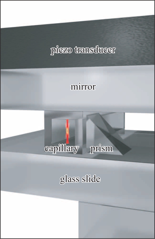
Figure 1 shows a schematic sketch of a typical probe chamber design. It consists of a piezo transducer (thickness 1 mm, Ferroperm Piezoceramics, Pz26), a dielectric mirror (thickness 1.1 mm, Edmund Optics, NT64-454), a square capillary (VitroCom 8240, inner diameter 0.4 mm, outer diameter 0.8 mm) filled with water, and a microscope slide (thickness 1.0 mm). For some applications with large probe volume we omit the capillary and instead use the complete volume between mirror and microscope slide, which are separated by spacers (thickness typically 0.3 mm). We use thin layers of glycerol as a coupling medium between the different layers to ensure proper acoustic coupling.
Fig. 1.
Probe chamber design. A rectangular capillary, filled with water, is sandwiched between a mirror on top and a microscope slide. The ultrasonic wave is excited by a piezo transducer on top of the stack. Next to the capillary a small prism, which acts as a mirror, provides an additional view from the side. The geometrical path length of the side-view imaging is longer than that of the direct-view. To compensate for this difference so that particles appear simultaneously sharp in the direct and side-view image, we add another mounting slide that covers only the area below the prism but not below the capillary.
At the fluid/glass interfaces, due to the different acoustic impedances, strong reflections of acoustic waves occur that lead to a standing wave pattern within the fluid layer. Choosing an excitation frequency f of the order of 2 MHz such that the wavelength λ = c/f approximates to λ/2 = dfluid we resonantly excite a standing wave with a single horizontal nodal plane of the acoustic pressure vertically centered within the fluid volume. In a similar manner we are able to create standing wave patterns with several nodal planes at higher frequencies. As discussed in more detail later, the acoustic radiation pressure of the ultrasonic standing wave confines particles like polystyrene beads, cells or micro-organisms within such a nodal plane.
To achieve an optimum acoustic efficiency it is required to carefully choose the dimensions of the individual layers. However, in our setup we were using only readily available standard components with thicknesses that only roughly match the optimized design. Nevertheless we observe in our setup acoustic trapping forces, which are strong enough to hold particles like polystyrene beads or micro-organisms in water against gravity with a modest driving voltage of a few Volts, such that a standard function generator (Agilent 33220A, 50 Ω output impedance) is sufficient to directly drive the piezo transducer.
To characterize the acoustic properties of our probe chamber design for more quantitative measurements, we performed simulations based on a simple one-dimensional model [12]. Since we did not know the precise material properties (especially the speed of sound) of the individual components of our probe chamber setup beforehand, we experimentally determined the frequencies of the most prominent resonances for several fluid layer thicknesses, using measurements as presented later in Fig. 3 and Fig. 6. These data allowed us to determine the unknown material properties, see Table 1. In turn, we use this 1D-model with the adjusted parameters to calculate the expected acoustic force profiles for various conditions, and based on these results we chose proper dimensions of the probe chamber.
Fig. 3.
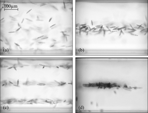
Side-view images of acoustic trapping of motile micro-organisms (Euglena gracilis), see Media 1 (4.8MB, MOV) . (a) The acoustic trap is off, the micro-organisms are randomly distributed within the probe volume. (b) Acoustic trap switched on (f = 1.95 MHz), specimens are confined in single nodal plane. (c) Trapping with resonance at f = 5.77 MHz with three nodal planes. (d) Aggregation of specimens due to additional horizontal confinement.
Fig. 6.
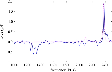
Measurement of the dependence of the acoustic force on on the excitation frequency for a 5.8 μm diameter polystyrene bead in water. These data are valid for a probe chamber with 0.62 mm fluid layer thickness, the other probe chamber dimensions are given in table 1. The optically trapped bead was placed 400 μm above the bottom, and the driving voltage of the ultrasound transducer was 3Vp–p. Also shown are the results of our model calculations (dashed line). We scaled the calculated force such that the peak value for the most prominent resonance at 2380 kHz matches the observed data.
Table 1.
Material properties and typical layer thicknesses of the individual components of the probe chamber used for the simulation of the acoustic properties of the probe chamber. The thicknesses are measured values, the sound velocities have been adjusted such that the simulated resonance frequencies match the actual ones. The densities are estimates taken from tabulated values.
| component | thickness (mm) | sound velocity (m/s) | density (kg/m3 |
|---|---|---|---|
| piezo transducer | 1.0 | 4780 | 7700 |
| mirror | 1.1 | 3800 | 2200 |
| mounting slide | 1.0 | 6200 | 2200 |
The acoustic force acting on a spherical particle that is significantly smaller than the acoustic wavelength, with density ρp and sound velocity cp is related to the acoustic pressure p(r) at position r within a fluid of density ρ and sound velocity c by [13, 14]
| (1) |
where and are dimensionless parameters that depend on the material properties of the particle and the fluid, and , where λ is the wavelength of the acoustic wave. The force scales with the volume V of the particle and the square of the sound pressure p. For a plane standing wave with sound pressure amplitude p(z) = p0 cos(kz) the acoustic force shows a dependence on the vertical z-position given by
| (2) |
For polystyrene particles in water f1 = 0.6 and f2 = 0.03, the first term in Eq. (1) dominates and from Eq. (2) they are trapped at pressure nodes. Similar results hold for cells or micro-organisms.
For an idealized λ/2-resonator this force has the shape of a full period sinusoid that leads to a stable trapping position in the center and vanishing force at the top and bottom boundaries. However, for a real system with a finite acoustic impedance at the fluid/glass interfaces, the force does not necessarily vanish at the boundaries. By properly choosing the parameters of the probe chamber design it is possible to design force profiles that push particles towards or away from the interface [15].
2.2. Optical trapping
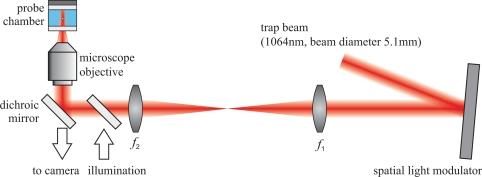
Figure 2 shows the setup of the optical trap, which we called optical macro-tweezers, and which is the starting point for the combined trap. In [10] we give a detailed description. As a light source we use an Ytterbium doped fiber laser (model PYL-10-1064-LP from IPG Photonics, max. 10 W) at a wavelength of 1064 nm. We holographically shape the beam by a phase-only spatial light modulator (model HEO 1080 P from HOLOEYE Photonics, resolution 1920 × 1080, pixel size 8 μm) into several copropagating beams with different divergencies and beam directions. These beams are coupled into an inverted optical microscope (Zeiss Axiovert 135) with two lenses (f1 = 200mm, f2 = 250mm) and a dichroic mirror, which image the SLM plane onto the back aperture of the microscope objective (Zeiss N-Achroplan 10×, NA 0.25 or Zeiss Fluar 5×, NA 0.2). These microscope objectives, which we employ for both imaging and focusing of the trapping light, have a much lower numerical aperture (NA) and magnification than typically used for single-beam optical tweezers. Consequently, both the working distance of 6 mm (12 mm) and the object field diameter of 2.3 mm (4 mm, respectively) are much larger. For illumination we couple the light from a green LED with a dichroic mirror into the beam path. The silver coated surface of the piezo transducer on top of the probe chamber acts as a diffuse reflector for the illumination light.
Fig. 2.
Schematic sketch of the experimental setup. We illuminate the spatial light modulator (SLM) with a collimated laser beam. With two lenses (f1 = 200mm, f2 = 250mm) and a dichroic mirror we couple the first diffraction order into an inverted optical microscope. See text for more details on the individual parts.
Within the probe volume, which is located 100–1000 μm in front of a plane mirror, we create a light configuration that resembles that of a counter-propagating beam trap. Radially the trapping relies on the optical gradient forces, whereas axially it is the balancing of the scattering forces. The maximum achievable optical forces in the radial and axial directions are similar, but the trap stiffness in the axial direction is about 10 times weaker than in the radial direction due to the larger trapping range. By an active feedback loop, which modifies the relative intensities of the counter-propagating beams, the effective trap stiffness can be strongly increased [16].
In addition to the above described basic features we equipped our setup with further enhancements, which are not necessary for optical trapping, but which improve the usability and convenience of our setup. We control the trap parameters such as trap position, separation of the foci or relative beam intensity in real-time. For this we change the phase pattern on the SLM, which is connected to a computer via a DVI-interface. For fast calculations of the phase pattern we utilize a graphics card (AMD Radeon 5850), the update rate is limited by the refresh rate of the SLM (60 Hz).
The distance of the microscope objective to the mirror strongly influences the light configuration. We therefore continuously measure the position with a rotary encoder, which is coupled to the focusing mechanics of the microscope and adjust the beam parameters in such a way that the optical trap always stays at the same distance, independent of the objective position. This feature is very convenient for the observation of the trapped particles, since thereby we can change the focal plane for imaging as usual without affecting the optical trap.
Furthermore, a small prism as shown in Fig. 1 (size 0.7 mm), which acts as a mirror, allows us to gain access to a side-view, using the same microscope objective for imaging from two sides and trapping. For the illumination of the side-view we employ an acrylic fiber (0.75 mm diameter) placed on the opposite side of the capillary, that fits between the empty space between mounting slide and dichroic mirror. While this prism is not essential for trapping, it directly provides useful information about the vertical position of trapped particles.
3. Results
3.1. Enrichment and levitation of specimens by acoustic trapping
The effect of the acoustic forces on motile micro-organisms (Euglena gracilis) is demonstrated in Fig. 3 ( Media 1 (4.8MB, MOV) ), which shows side-view images. When the acoustic trap is switched on, the micro-organisms are confined to specific horizontal planes. They are free to move within such a plane. This confinement of all particles within a single plane is very useful for the observation of actively swimming organisms, since they are all in focus when imaged from the direct-view direction, see Fig. 4. This method has advantages compared to confinement within a thin probe chamber. It allows us to use much larger probe volumes, from which all particles are concentrated within the nodal plane, where several organisms can be watched simultaneously. Unwanted influences from contact to a surface, e.g. sticking to the surface or hydrodynamic interactions are avoided.
Fig. 4.
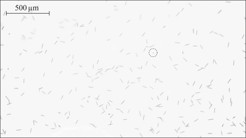
Combined acoustic and optical trapping of micro-organisms (Euglena gracilis). Shown is a direct-view image, selected from Media 2 (4.1MB, MOV) . The acoustic trap confines all micro-organisms within the focal plane. A single organism (marked by a circle) is trapped in the optical trap. It aligns along the (vertical) laser beam and appears point-like. Within 40 s the optical trap has been moved by a distance of about 1 mm, dragging the organism across the field of view.
At certain frequencies we also observe an additional horizontal confinement due to coupling of the acoustic wave from the vertical into the horizontal directions, especially within our setup employing a capillary. Since our probe chamber is not optimized for this, this additional horizontal confinement is less pronounced and is very sensitive on the experimental settings, e.g. on the excitation frequency. Nevertheless it leads to useful effects such as the accumulation of a large number of particles (additional confinement along the long axis of the capillary) or trapping of particles along a line. It is also possible to avoid the horizontal confinement in cases when it is not wanted. We observed that by slightly modulating the ultrasound frequency (typical settings: 20 kHz frequency deviation, modulation frequency 1 kHz), we are able to significantly suppress unwanted horizontal confinement due to an averaging effect over several different standing wave patterns.
3.2. Combined optical and acoustic trapping
Figure 4 ( Media 2 (4.1MB, MOV) ) demonstrates the combined acoustic and optical trapping of actively swimming micro-organisms (Euglena gracilis). In contrast to Fig. 3, images from the direct-view are shown. Instead of using a capillary we used the whole available space between mounting slide and mirror as the probe volume. Acoustic trapping is manifested by the fact that all micro-organisms are confined within the focal plane. At the same time, a single organism is optically trapped and dragged over a distance of more than 1 mm. During the movement, which was interactively controlled by hand, we took care to avoid collisions. This demonstrates the high selectivity and control of optical trapping. Furthermore, these images show the advantage of having a large field of view, which reaches a diameter of 4 mm for visual inspection, the images only show a smaller range. In this setup the large scale trapping capabilities of the acoustic trap can be efficiently exploited, e.g. for working with samples taken from the environment, which are typically more dilute.
In the previous demonstration we used acoustic trapping as a useful tool for confining and concentrating particles, which strongly enhances the applicability of optical trapping with our macro-tweezers setup for practical purposes. In the following example we show that the combined acoustic and optical trapping enables applications that are not possible with each method applied individually. Such a case is the micro-manipulation of large particles. For large particles (size above 50 μm) gravity becomes dominant, as it scales with the volume of the particle, whereas, e.g., drag forces only scale with the diameter of the particle. Due to the favorable fact that the acoustic force scales with the volume of the particle too (see Eq. (1)), levitation of large particles is preferably performed with an acoustic trap, since the optical forces are limited by the maximum available or reasonably applicable laser power. Moving an acoustically levitated particle with an optical trap requires much less power than holding it against gravity only by optical forces. In the combined acoustic and optical trap we were able to trap polystyrene beads with a diameter of 75 μm, large micro-organisms (dinoflagellates) with sizes of about 70 μm, and potato starch grains, see Fig. 5. To hold these particles in water against gravity, forces of about 100 pN for the 75 μm bead and 1000 pN for the starch grain are necessary. The force for the starch grain is much larger because of the higher density of about 1550 kg/m3, compared to about 1050 kg/m3 for polystyrene. Media 3 (976.3KB, MOV) , 4 (360KB, MOV) , and 5 (707.5KB, MOV) demonstrate the manipulation of these particles with optical forces while they are levitated by the acoustic trap.
Fig. 5.
Trapping of large particles in the combined acoustic and optical trap: (a) polystyrene bead, diameter 75 μm ( Media 3 (976.3KB, MOV) ), (b) living Dinoflagellate micro-organism, size approx. 70 μm ( Media 4 (360KB, MOV) ), (c) potato starch grain, size 95 μm×60 μm×60 μm ( Media 5 (707.5KB, MOV) ).
In these applications the vertical confinement of the acoustic trap typically dominates over any vertical forces of the optical trap. In this case it is even possible to work with experimental settings where there is no optical confinement along the vertical axis in our macro-tweezers configuration, e.g. if the focus separation of the two counter-propagating beams is very small or only a single beam is used. This allows us to optimize the settings for maximum optical forces within the horizontal plane, e.g. choosing a focus at the particle position, without the need to care about the vertical trapping conditions.
3.3. Characterization of acoustic forces
In this section we present quantitative measurements of the acoustic trapping forces, where we used the optical trap as a tool to perform these measurements. These data are important to assess proper trapping conditions for applications.
The excitation frequency of the acoustic trap is a very important experimental parameter, since the amplitude of the resonant standing wave and consequently the acoustic forces depend sensitively on it. It is necessary to carefully tune the frequency to one of the resonances. To perform a measurement of the acoustic forces we optically trapped the bead and measured the vertical excursion of it depending on the frequency. For this we immersed a small prism (size 0.5 mm) in the fluid layer, which allows us to directly observe the vertical particle position. From a calibration of the stiffness of the optical trap we determine the acoustic forces acting on the bead. Figure 6 shows the frequency dependence of the acoustic force on a 5.8 μm polystyrene bead. We observe a resonance structure that due to the excitation of non-planar acoustic modes shows more features than our simple one-dimensional model is able to explain, but the main features coincide with our model. In a setup employing a rectangular capillary the situation is even more complex and a one-dimensional model is not sufficient for a detailed description. Using the optical trap allows us to take quantitative measurements of the acoustic force in such a setup [14].
We also experimentally studied the dependence of the acoustic force on the vertical position. For this we used a more convenient method than repeatedly measuring the excursion from the optical trap at different positions: we first placed polystyrene beads with help of the optical trap at the top or bottom boundary of the probe chamber and then we switched on the acoustic trap. The particles are driven towards the central nodal plane. From a video of this movement, taken from the side-view, we determined position and velocity of the particle. The expression for the drag force
| (3) |
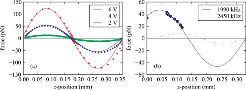
acting on a spherical particle with radius r, moving at a speed v in a viscous fluid with dynamic viscosity η (≈ 0.9 × 10⁻³ Pa s for water) relates the exerted force to the observed particle velocity. Some results of the force profiles along the vertical direction for several ultrasound amplitudes are shown in Fig. 7(a). The force profile is well represented by a sinusoidal shape as described by Eq. (2). As expected, the force scales with the square of the sound pressure p, which is proportional to the driving voltage of the piezo transducer. At the maximum driving voltage of U = 10Vp–p we expect in this setup for a 20 μm polystyrene bead in water a maximum acoustic force of about 350 pN. According to Eq. (2) this corresponds to a sound pressure amplitude of 0.4 MPa. These acoustic forces are much stronger than the force of 2.1 pN needed to hold the 20 μm beads against gravity.
Fig. 7.
(a) Force profiles for polystyrene beads (20 μm diameter) in the acoustic trap for different ultrasonic amplitudes. We performed the measurements in a capillary as depicted in Fig. 1 at an ultrasound frequency of f = 1911 kHz. The solid lines are based on a sinusoidal fit, which has been scaled accordingly to F ∝ U2, where U is the driving voltage of the piezo transducer. (b) Force profiles for a 0.33 mm thick probe chamber for two different resonances. At 1990 kHz we observe at the bottom of the probe volume (z = 0) a large lifting force of about 75% of the maximum acoustic force, whereas at 2450 kHz our model predicts a force pushing particles against the bottom. The data was measured with a starch grain of 23 μm diameter and is valid for a driving voltage of 0.73Vp–p, which is sufficient to detach such particles from the bottom.
Furthermore we observe for the given impedances and thicknesses of the setup employing a capillary at the bottom of the chamber a non-vanishing acoustic force of about 10% of the maximum force. This lifting force is very useful to detach particles that have settled to the bottom.
In a different probe chamber setup with a 1.25 mm thick mounting slide and a 0.33 mm thick water volume instead of the capillary, we observe a large lifting force of about 75% of the maximum force (resonance frequency f = 1995 kHz). In contrast, for another resonance at f = 2450 kHz in the same setup the residual force at the bottom boundary is directed towards the glass surface and a release of particles from the surface is avoided. Since in this setup the fluid volume is too thin to immerse a prism, we used another method to characterize the force profile. By refocusing we measured the vertical equilibrium positions zi of a starch grain for several driving voltages Ui, where the acoustic force equals the gravitational force FUi (zi) = Fgrav. Since the acoustic force scales with U2, i.e., FUi (zi) = (Ui/U0)2 F0(zi), where F0(z) denotes the force profile for some reference voltage U0, the force profile is proportional to . The starch grain was horizontally confined by a weak optical trap with a negligible vertical force. These measurements confirm the predictions of our one-dimensional model calculations, as shown in Fig. 7(b). In this probe chamber design a driving voltage of 0.73Vp–p is sufficient to detach a starch grain from the bottom surface, creating a lifting force of about 35 pN for a starch grain with a size of about 23 μm.
3.4. Active particle sorting
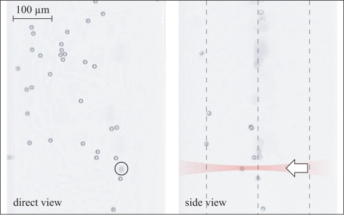
As a final demonstration we show the use of combined optical and acoustic trapping for active particle sorting in a microfluidic environment, see Fig. 8 ( Media 6 (2.1MB, MOV) ). The idea is to use acoustic trapping to confine particles within three nodal planes and to interactively redistribute the particles between these planes with optical forces.
Fig. 8.
Active particle sorting ( Media 6 (2.1MB, MOV) ). In a first trapping stage we prepare 10 μm polystyrene beads in a continuous flow with a speed of about 20 μm/s to occupy a plane centered vertically in the capillary. Then they enter the region shown in this image with three nodal planes, where some particles are selectively pushed with optical forces to the upper plane. Also shown in this image are markers indicating the positions of the nodal planes and the laser beam.
In this application we use two acoustic traps, created by two separate piezo transducers (size 6mm × 6mm × 1mm) placed next to each other along the capillary. We create a continuous flow along the capillary by injecting fluid with a thin capillary (diameter about 70 μm), which is attached to a micro pipette aid. In the first acoustic trapping stage, which is tuned to a resonance with a single nodal plane, particles are pushed to the center. Subsequently the particles are injected into the central plane of the next stage with three nodal planes. In this area all particles are initially contained in the central plane, and there we apply our optical trap to push particles to the top or bottom plane. For this it is not even required to have an optical trap along the vertical direction, but a single laser beam pointing up- or downwards is enough. This configuration makes use of the strong scattering forces along the beam axis. Particles contained in different planes can afterwards be completely separated, e.g., with a small capillary, sucking in particles from a single plane only.
4. Conclusions
The combination of acoustic and optical trapping in our setup enhances the large scale trapping abilities of acoustic forces with the high precision, selectivity and flexibility of optical trapping. We present several useful cases. First, acoustic trapping amends our optical trapping setup since it confines all particles within a specific plane, which is very convenient. Typical problems like sinking and sticking of particles to the bottom are avoided, and the enrichment of specimens within the focal plane allows us to work with dilute samples. The favorable scaling properties of acoustic forces enables levitation of large particles, which then can be manipulated by optical means. This advances optical micromanipulation to a considerably increased range of particle sizes. Following another route, the well established capabilities of optical trapping to measure small forces offer new possibilities to characterize and thus optimize acoustic trapping. Our combined acoustic and optical trapping method is compatible with typical microfluidic setups. We demonstrate the implementation of active particle sorting. Here acoustic trapping acts as a sort of invisible, reconfigurable microfluidic device. Instead of realizing a fixed pattern of channels we create a force field which confines particles in different planes, between which particles are selectively pushed with optical forces in an efficient manner.
With our optical macro-tweezers setup the integration of acoustic trapping is very easy to accomplish, and due to the large field of view the advantages of acoustic trapping can be well exploited. We therefore envisage that our method will find a broad range of applications.
Acknowledgments
The present work was supported by the ERC Advanced Grant catchIT (No. 247024).
References and links
- 1.Ashkin A., Optical Trapping and Manipulation of Neutral Particles using Lasers (World Scientific, 2006). 10.1142/9789812774897 [DOI] [PMC free article] [PubMed] [Google Scholar]
- 2.Jonáš A., Zemánek P., “Light at work: The use of optical forces for particle manipulation, sorting, and analysis,” Electrophoresis 29, 4813–4851 (2008). 10.1002/elps.200800484 [DOI] [PubMed] [Google Scholar]
- 3.Vandaele V., Lambert P., Delchambre A., “Non-contact handling in microassembly: Acoustical levitation,” Precis. Eng. 29, 491–505 (2005). 10.1016/j.precisioneng.2005.03.003 [DOI] [Google Scholar]
- 4.Nilsson J., Evander M., Hammarström B., Laurell T., “Review of cell and particle trapping in microfluidic systems,” Anal. Chim. Acta 649, 141–157 (2009). 10.1016/j.aca.2009.07.017 [DOI] [PubMed] [Google Scholar]
- 5.Padgett M., Di Leonardo R., “Holographic optical tweezers and their relevance to lab on chip devices,” Lab Chip 11, 1196–1205 (2011). 10.1039/c0lc00526f [DOI] [PubMed] [Google Scholar]
- 6.Dholakia K., Čižmár T., “Shaping the future of manipulation,” Nat. Photonics 5, 335–342 (2011). 10.1038/nphoton.2011.80 [DOI] [Google Scholar]
- 7.Hultström J., Manneberg O., Dopf K., Hertz H. M., Brismar H., Wiklund M., “Proliferation and viability of adherent cells manipulated by standing-wave ultrasound in a microfluidic chip.” Ultrasound Med. Biol. 33, 145–151 (2007). 10.1016/j.ultrasmedbio.2006.07.024 [DOI] [PubMed] [Google Scholar]
- 8.Bazou D., Kearney R., Mansergh F., Bourdon C., Farrar J., Wride M., “Gene expression analysis of mouse embryonic stem cells following levitation in an ultrasound standing wave trap,” Ultrasound Med. Biol. 37, 321–330 (2011). 10.1016/j.ultrasmedbio.2010.10.019 [DOI] [PMC free article] [PubMed] [Google Scholar]
- 9.Pitzek M., Steiger R., Thalhammer G., Bernet S., Ritsch-Marte M., “Optical mirror trap with a large field of view,” Opt. Express 17, 19414–19423 (2009). 10.1364/OE.17.019414 [DOI] [PubMed] [Google Scholar]
- 10.Thalhammer G., Steiger R., Bernet S., Ritsch-Marte M., “Optical macro-tweezers: trapping of highly motile micro-organisms,” J. Opt. 13, 044024 (2011). 10.1088/2040-8978/13/4/044024 [DOI] [Google Scholar]
- 11.Ashkin A., “Acceleration and trapping of particles by radiation pressure,” Phys. Rev. Lett. 24, 156–159 (1970). 10.1103/PhysRevLett.24.156 [DOI] [Google Scholar]
- 12.Hill M., Shen Y., Hawkes J. J., “Modelling of layered resonators for ultrasonic separation,” Ultrasonics 40, 385–392 (2002). 10.1016/S0041-624X(02)00127-0 [DOI] [PubMed] [Google Scholar]
- 13.Gor’kov L. P., “On the forces acting on a small particle in an acoustical field in an ideal fluid,” Sov. Phys. Dokl. 6, 773–775 (1962). [Google Scholar]
- 14.Barnkob R., Augustsson P., Laurell T., Bruus H., “Measuring the local pressure amplitude in microchannel acoustophoresis,” Lab Chip 10, 563–570 (2010). 10.1039/b920376a [DOI] [PubMed] [Google Scholar]
- 15.Hill M., “The selection of layer thicknesses to control acoustic radiation force profiles in layered resonators,” J. Acoust. Soc. Am. 114, 2654–2661 (2003). 10.1121/1.1616581 [DOI] [PubMed] [Google Scholar]
- 16.Bowman R., Jesacher A., Thalhammer G., Gibson G., Ritsch-Marte M., Padgett M., “Position clamping in a holographic counterpropagating optical trap,” Opt. Express 19, 9908–9914 (2011). 10.1364/OE.19.009908 [DOI] [PubMed] [Google Scholar]


