Abstract
Ni with different purities between 99.69 and 99.99 wt.% was deformed by high-pressure torsion (HPT) to high strains, where no further refinement of the microstructure is observed. The HPT deformation temperature varied between −196 and 400 °C. Both impurities and temperature significantly affect the lower limit of the grain size obtained by HPT. In the investigated samples, carbon was the most important impurity element in controlling the limit of grain refinement. The decrease in grain size due to an increase in the carbon content from 0.008 to 0.06 wt.% for HPT-deformed Ni samples at room temperature enhanced the ultimate tensile strength from 1000 to 1700 MPa. Surprisingly, the carbon content did not deteriorate the ductility, defined as the reduction in area, which is mainly limited by the total amount of impurities besides carbon. Furthermore, the deformation temperature dependency on ductility was not very pronounced and only visible for deformation temperatures above 200 °C.
Keywords: Severe plastic deformation, High-pressure torsion, Nickel, Carbon, Influence of impurities
1. Introduction
Interest in severe plastic deformation (SPD) has recently increased as it can provide ultrafine and nanograined bulk metals in industrial dimensions. SPD materials are of particular interest due to their interesting mechanical and physical properties. Most of these properties are related to the nanometer-scaled grain size. In the last few years, research has focused on understanding the fragmentation process and the limitation of the final grain size [1–4]. Deformation temperature, alloying and strain path are the dominant factors controlling the saturation grain size in single-phase materials [1]. Most of these concepts are based on experiments performed on high-purity materials such as Al, Cu or Ni. Only a few studies are related to the question of how low impurity contents (<0.5 wt.%) influence the final microstructure [5].
Ni is one of the model materials used for SPD processing [6–11]. In the last few years we have used different pure Ni grades for SPD processing several times. Unexpected significant changes in the hardness were observed, so a more systematic analysis of the effect of impurities on the hardness and structural evolution was performed. It has already been shown that impurity and deformation temperature have strong effects on refinement. However, how the different impurities affect the saturation grain size was not investigated, nor how the strain needed to reach the saturation in refinement is affected by the deformation temperature. Therefore the temperature was varied from −196 to 400 °C to understand the phenomena controlling the refinement during SPD better. Besides the effect of impurities on microstructure and hardness, the influence on the tensile strength and ductility has been studied too.
2. Experimental
Commercial Ni rods of different purities, ranging between 99.69 and 99.99 wt.%, were investigated in this study. Additional carbon-doped Ni samples were produced to understand the influence of carbon on the saturation microstructure. The total carbon content, the total impurity amount and the detected impurity elements are listed in Table 1. In the case of the Ni-doped samples, a 99.99 wt.% purity material (Ni99.99) with the corresponding graphite mass was arc melted. To guarantee a homogeneous carbon distribution, all samples were re-melted at least three times. Afterwards the carbon content was determined using a carbon determinator (C/S Leco® 125). The type and amount of included impurity elements were taken from the materials analysis provided by the supplier.
Table 1.
Material used in this study with the purity given in wt.% and ppm, otherwise carbon concentration and impurity elements in ppm.
| Material | Ni (wt.%) | Total impurity content (ppm) | Carbon content (ppm) | Impurity elements (ppm) |
|---|---|---|---|---|
| Ni99.99 | 99.996 | 41 | 8 | Al(2.9), Ca(<1), Co(1.9), Cr(2.065), Cu(2), Fe(12.15), Ir(0.32), Mo(0.48), Nb(0.1), Re(0.23), Sb(0.3), Si(0.17), Ta(<1), V(8.1) |
| Ni–300ppmC | 99.972 | 283 | 250 | |
| Ni–600ppmC | 99.950 | 518 | 485 | |
| Ni–1200ppmC | 99.880 | 1.200 | 1167 | |
| Ni99.79 | 99.789 | 2.110 | 600 | Cu(<100), Fe(<100), Mn(1100), S(10), Si(200) |
| Ni99.69 | 99.687 | 3.130 | 100 | Co(300), Cu(1600), Fe(400), Mn(300), P(200), S(<30), Si(200) |
Discs from the different materials were deformed under the same conditions using a constrained high-pressure torsion (HPT) tool [12]. The deformation temperature for the commercial Ni was varied from liquid nitrogen temperature up to 400 °C to study the effect of impurities in the different temperature regimes. Carbon-doped samples were only deformed at room temperature. All of the discs, 8 mm in diameter, were rotated three times under an applied pressure of 4 GPa and a rotation speed of 0.2 rpm. The equivalent strain at a radius of 3 mm was about 55, which is calculated using Eq. (1), where r is the radius of interest, n the number of rotations and h the sample thickness:
| (1) |
Further details concerning the whole HPT process and the heating/cooling setup used are described elsewhere [1,12,13]. After HPT deformation, the microstructure was investigated with Vickers hardness tests using a Buehler® Micromet 5104 and a load of 500 g. The indents were made on the top surface in radial direction, with a spacing of 250 μm between indents. Tensile tests were carried out using a Kammrath & Weiss® tensile stage with a 2 kN load cell. The dog-bone-shaped samples were tested at room temperature with a test speed of 2.0 μm s−1. The displacement was measured by the movement of the cross head. Two samples were machined from one HPT disc with a gauge length of 2.5 mm and a cross-section of 0.5 × 0.5 mm. Fracture surfaces were investigated using by scanning electron microscopy (SEM). In this study, ductility was defined as reduction in area. From the micrographs, the reduction in area was calculated according to Eq. (2):
| (2) |
where A0 is the initial cross-sectional area and A1 is the remaining fracture area. In addition, an atom probe test was carried out to investigate the distribution of carbon in the final HPT microstructure. The atom probe sample was prepared from the region of the sample where even further deformation would not change the final achieved microstructure [14].
3. Results
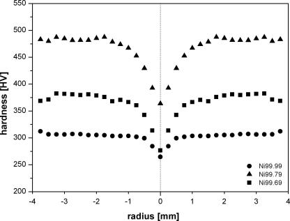
Fig. 1a shows the hardness profiles of three different commercial nickels (Ni99.99, Ni99.79 and Ni99.69) HPT deformed at room temperature. The samples exhibit the typical hardness distribution of HPT samples which are partly deformed to saturation [12]. Surprisingly, the Ni99.79 shows the highest saturation hardness. Ni99.69, with a somewhat higher impurity level, has a significantly low saturation hardness, which is 100 HV less than the Ni99.79. We assumed that the difference in the carbon content causes this behavior; therefore, carbon-doped samples were prepared to validate this hypothesis. Ni99.99 deformed at room temperature reaches the same saturation hardness as a 10 mm nickel disc (99.99 wt.%) deformed for 10 and 20 revolutions [11], which verifies that even further straining will not change the saturation hardness.
Fig. 1a.
Hardness profiles for Ni99.99, Ni99.79 and Ni99.69 along the HPT-disc radius deformed to 3 revolutions: All samples show a saturation region but the saturation hardness does not correspond to the total impurity content.
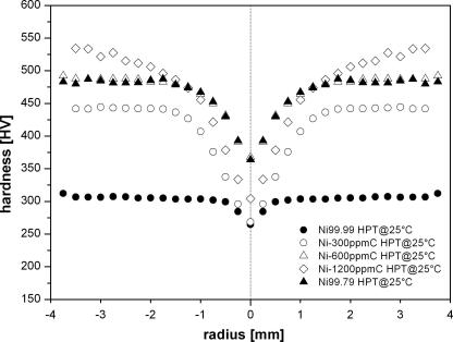
Fig. 1b shows the hardness profiles of the three carbon-doped samples with a carbon content of 300 ppm (Ni–300ppmC), 600 ppm (Ni–600ppmC) and 1200 ppm (Ni–1200ppmC). An increasing carbon content causes a significant increase in hardness. In the case of Ni–1200ppmC, no saturation was achieved after three rotations. For comparison, the hardness profile of Ni99.79 is also plotted in Fig. 1b. This curve closely follows that of Ni–600ppmC; both have a carbon content of 600 ppm, but there is an impurity difference of 0.15 wt.%. An increase in the carbon content from 8 ppm (Ni99.99) up to 1200 ppm (Ni–1200ppmC) is reflected by a hardness increase of 200 HV, which is quite surprising.
Fig. 1b.
Hardness profiles for carbon-doped samples along the HPT-disc radius deformed to 3 revolutions: With increasing carbon content saturation hardness also increases.
To understand the influence of temperature on the final microstructure, a systematic investigation on two Ni grades (Ni99.99 and Ni99.79), with different purities (99.99 and 99.79) and carbon contents (8 and 600 ppm), was carried out. The discs were deformed at four different temperatures: liquid nitrogen (−196 °C), room temperature (∼25 °C), 200 °C and 400 °C. Hardness profiles for both materials at the different deformation temperatures are shown in Fig. 2.
Fig. 2.
Hardness profiles of Ni 99.79 and Ni99.99 for the different HPT-deformation temperatures are shown. It has to be noted that r = 0 given in the plot might not be the exact position of the deformation center.
Ni99.79 HPT deformed at 400 °C achieves higher hardness values compared to Ni99.99 HPT deformed at −196 °C. Both Ni grades show the same temperature trend, with a decreasing deformation temperature leading to an increasing hardness. The temperature-related hardness gap is larger for Ni99.99 compared to Ni99.79. All hardness profiles exhibit a saturation at a radius of about 1 mm, which corresponds to an equivalent strain of about 20. The differences in hardness vs. radius behavior of small radii is caused by the inaccuracy of the sample positioning when the measured center is not identical to the deformation center. Figs. 1 and 2 indicate that with decreasing deformation temperature as well as with increasing impurity content, especially carbon, the onset of saturation is shifted to a larger radius, which implies that larger strains are required to achieve saturation. Due to the fact that the hardness follows the same trend, and considering the Hall–Petch relationship, a possible explanation might be related to the misorientation between two grains. Smaller grains need a greater strain to achieve a similar storage dislocation density compared to large grains.
Tensile tests were carried out to determine the ductility of the different Ni purities. Tensile curves of the carbon-doped samples are shown in Fig. 3. The ultimate tensile strength increases with the carbon content. A comparison of the tensile strength and the obtained microhardness indicates that the Tabor factor, c (H = cσy) of all samples is in the range of 2.8–3.2, which fits quite well to the theoretical value of 3 [15]. The tensile curves of the starting material (Ni99.99) and of Ni99.79 are also shown in Fig. 3. HPT Ni99.79 has a higher ultimate strength than Ni–600ppmC, which is related to a slightly lower carbon content and indicates how sensitive HPT Ni reacts on carbon. HPT deformation for three revolutions of Ni–1200ppmC is not enough to achieve saturation (Fig. 1b); therefore, even at the larger radii of the HPT samples, a gradient in hardness is observed.
Fig. 3.
Tensile curves of carbon-doped Ni samples, Ni99.99 and Ni99.79.
The tensile samples were taken at a radius of 2 mm, when the measured hardness is similar to the saturation hardness of Ni99.79 (Fig. 1b) and hence the ultimate tensile strength is similar. The total displacement at fracture of all carbon-doped samples is similar to that of Ni99.99. Only Ni–600ppmC shows a shorter total displacement to fracture, but this is related to the average calculation of the tensile curve. The average curve is calculated up to the first sample fractured, which is the total displacement at fracture plotted in Fig. 3.
Fracture surfaces of the tensile samples were investigated by SEM. Typical examples are shown in Fig. 4. Pores and dimples were observed on the fracture surface, which indicates a ductile fracture behavior. Fig. 7 depicts a bar plot of the reduction in area as a function of the carbon content. All carbon-doped samples were in the range of the starting material (Ni99.99), which had a reduction in area of around 70%.
Fig. 4.
SEM images of the fracture surface of the carbon-doped samples and Ni99.99 (starting material) HPT-deformed at room temperature: (a) Ni99.99, (b) Ni–300ppmC, (c) Ni–600ppmC, (d) Ni–1200ppmC.
Fig. 7.
Reduction in area shown for Ni99.99, Ni99.79 and carbon-doped samples according to their HPT-deformation temperature.
Fig. 5 shows the stress vs. displacement curves for Ni99.79 and Ni99.99 HPT deformed at different temperatures. Similar to the hardness test, the total impurity and carbon content have a stronger influence on the strength than the deformation temperature. Even a Ni99.79 deformed at 400 °C achieves higher strength values compared to Ni99.99 deformed at liquid nitrogen temperature (−196 °C). The highest ultimate strength value was achieved by Ni99.79 deformed at liquid nitrogen temperature. In contrast, the lowest ultimate tensile strength value was observed in the Ni99.99 deformed at 400 °C. The hardness is about three times the ultimate strength, which is close to the theoretical Tabor value [15]. The total displacement at fracture for the Ni99.79 is smaller compared to the Ni99.99. However, the results are not significantly influenced by the HPT deformation temperature. Only Ni99.99 deformed at 400 °C shows a significantly larger total displacement at fracture compared to the other samples.
Fig. 5.
Room temperature tensile curves for Ni99.99 and Ni99.79 deformed at different HPT-deformation temperatures.
Significant necking was observed in all tensile samples. This is clearly visible from the SEM images of the fracture surfaces (Fig. 6). Inclusions, pores and dimples were observed on the fracture surface in the middle of the tensile sample (Figs. 12 and 13). The Ni99.99 samples show fewer inclusions and pores compared to the Ni99.79 samples.
Fig. 6.
SEM images of the fracture surface of Ni 99.99 and Ni99.79 deformed at different temperatures: (a) Ni99.99 HPT@ −196 °C, (b) Ni99.99 HPT@ −196 °C, (c) Ni99.99 HPT@ 25 °C, (d) Ni99.99 HPT@ 25 °C, (e) Ni99.99 HPT@ 200 °C, (f) Ni99.99 HPT@ 200 °C, (g) Ni99.99 HPT@ 400 °C, (h) Ni99.99 HPT@ 400 °C.
Fig. 12.
SEM micrograph of a fracture relevant inclusion in a pore in the middle of a tensile sample.
Fig. 13.
Details of the fracture surfaces of Ni99.99: (a) Ni99.99 HPT@ −196 °C, (b) Ni99.99 HPT@ 25 °C, (c) Ni99.99 HPT@ 200 °C and (d) Ni99.99 HPT@ 400 °C.
A bar plot of reduction in area vs. HPT deformation temperature is depicted in Fig. 7. In agreement with the observed change of the total displacement at fracture, a larger reduction in area is achieved by Ni99.99 compared to Ni99.79. In the case of Ni99.79, the reduction in area remains nearly constant at 50% independent of the HPT deformation temperature up to a deformation temperature of 200 °C, then increases to 68%. Ni99.99 shows this jump at an HPT deformation temperature of 200 °C, when the reduction in area increased from 70% up to 90%. Back-scattered electron (BSE) micrographs from the saturation region confirm that an increasing hardness or ultimate tensile strength is caused by a decreasing average grain size. This is clearly visible in the micrographs in Fig. 8. Ni99.79, deformed at liquid nitrogen temperature, achieved the finest microstructure (Fig. 8b), with an average grain size of about 50 nm. Using the same deformation temperature, the Ni99.99 reaches an average grain size somewhat less than 200 nm (Fig. 8a), which is quite similar to Ni99.79 HPT-deformed at 400 °C (Fig. 8d). The largest grains were observed in the Ni99.99 deformed at 400 °C with an average grain size about 1.4 μm (Fig. 8c). This micrograph was taken with the electron backscatter detection (EBSD) system. An electrolytic sample preparation was required because a mechanical polishing process would cause sub grain formation as a consequence of the small hardness. The temperature related change in microstructure for Ni99.99 (Fig. 8a and c) is more pronounced than for Ni99.79 (Fig. 8b and d).
Fig. 8.
BSE and EBSD – images of the saturation microstructure taken at a radius of 3 mm (a) Ni99.99 HPT@ −196 °C (BSE), (b) Ni99.79 HPT@ −196 °C (BSE), (c) Ni99.99 HPT@ 400 °C (EBSD –image quality map) and (d) Ni99.79 HPT@ 400 °C (BSE).
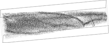
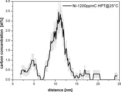
An atom probe analysis has been carried out on a HPT-deformed Ni–1200ppmC sample at room temperature to study the carbon distribution in the microstructure. Bars of dimension 0.3 mm × 0.3 mm × 7 mm of the HPT-deformed samples were cut out. Tips at a HPT-radius of 3 mm have been produced by a standard two step electrochemical polishing procedure [16]. The test was carried out on a LEAP 3000X HR from Cameca®, former Imago Scientific Instruments. A voltage mode measurement was not possible and therefore the sample was measured with a pulsed laser with a frequency of 200 kHz, a temperature of 30 K and a laser pulse energy 0.3 nJ. The software package IVAS 3.4.3 from Cameca® was used for reconstruction of the probed volume and the data analysis. Fig. 9a shows the carbon atom map of the investigated volume illustrating that the carbon is enriched along the interfaces which are suggested to be grain boundaries. The overall carbon composition of 0.73 at.% fits quite well to the estimated of 0.57 at.%. A carbon concentration profile perpendicular to the grain boundary is shown in Fig. 9b, revealing the carbon enrichment at the grain boundary.
Fig. 9a.
Carbon atom map of Ni–1200ppmC HTP-deformed at room temperature. The box size is 63 × 65 × 250 nm3.
Fig. 9b.
Carbon concentration profile in at.% perpendicular to a boundary marked in (a) by a cuboid. The cube size is 5 × 5 × 25 nm3 and the sampling volume thickness 1000 ions.
4. Discussion
4.1. Impurity influence on the final microstructure
This study clearly shows that from the investigated impurities listed in Table 1 only carbon has a significant influence on the final HPT-microstructure. Nevertheless, there could be a significant effect of other impurity element if their content is different. In literature, the influences of only a few elements on SPD Ni have been investigated. A well known element is silicon (<6.5 wt.%) which decreases the average grain size [17]. A finer HPT-microstructure is achieved using Ni oxides in HPT powder consolidation where the dispersed Ni oxides lead to a pinning of the grain boundaries [18]. Electrodeposited nanocrystalline Ni usually contains sulfur as a consequence of the production process. After deposition, the sulfur is dispersed in the grains but even at moderate temperature the sulfur diffuses to the grain boundaries [19]. This sulfur layer deteriorates the mechanical properties. The present investigation shows that both the carbon content and the deformation temperature have a significant influence on the final microstructure. This is clearly reflected in Fig. 10 where the saturation hardness of the different investigated nickels is plotted as a function of the carbon content. The effect of HPT deformation temperature is more pronounced at lower carbon content than at higher carbon content.
Fig. 10.
Saturation hardness of different HPT nickels deformed at room temperature vs. carbon content. A clear trend that a higher carbon content leads to a higher saturation hardness is visible.
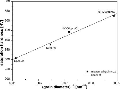
Fig. 11a shows that the hardness as a function of grain size, determined from EBSD analyses where only high angle boundaries (HAB) are taken into account, can be described by the Hall–Petch relation, Eq. (3), where H0 is the offset of the curve and d the grain diameter.
| (3) |
Fig. 11a.
Saturation hardness as a function of grain size diameter.
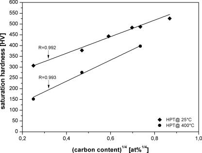
A similar linear relation is obtained in Eq. (4) when the hardness is plotted vs. , where c is the carbon concentration in atomic percentage and is the offset of the curve as shown in Fig. 11b.
| (4) |
Fig. 11b.
Saturation hardness as a function of the carbon content for two different HPT-deformation temperatures. The correlation coefficient of the linear fit is given by the value R.
In this figure only the data of the HPT-deformed samples at room temperature and 400 °C is shown. Similar curves can be obtained for the other HPT-deformation temperatures, however, with a different slope. Unfortunately not so many data are available to verify such linear relation for other HPT-deformation temperatures. The slope of the hardness vs. dependency decreases with decreasing HPT-deformation temperature which reflects that the impurities have a larger effect on the saturation grain size at higher HPT-deformation temperatures than at lower HPT-deformation temperatures. According to the work of Cahn, Luecke and Stuewe [20–22], impurities should influence the grain boundary mobility which is proposed to be the key parameter of the saturation grain size in SPD [1]. At higher SPD temperature the grain boundary velocity is governed by a process similar to hot deformation where as at low SPD temperatures strain induced boundary migration becomes dominant. Using Eqs. (3) and (4) and the assumption of d ∝ v, the grain boundary mobility, v, should be proportional to , such dependence are predicted for a wide range of impurity concentrations. At low SPD temperature, where strain induced boundary migration is dominant, the decreasing effect of the impurities should become less dominant. Hence, the slope in the H vs. relation decreases and the value increases.
4.2. Mechanical strength and ductility
The ductility of all carbon-doped samples is similar (Figs. 4 and 7) which indicates that no embrittlement due to the carbon content at the grain boundary does occur. The ductility is mainly governed by the number of non metallic inclusions which serves as micro defects but there is still a HPT deformation temperature dependency during the fracture event visible. In the region near the ultimate tensile strength, these micro defects in the middle of the sample start to grow and build up pores as for example shown in Fig. 12.
In Fig. 13 details of the fracture surface of the Ni99.99 tensile samples deformed at different temperatures are shown. In case of the 400 °C HPT-deformed samples these inclusions cause pores coalescence until final fracture occurs (Fig. 13d). Samples deformed at liquid nitrogen temperature (Fig. 13a) or room temperature (Fig. 13b) still shows large pores caused by large inclusions. Between these large pores small pores are generated which finally forms a dimpled fracture surface without inclusions. These small pores are a consequence of the multi-axial stress distribution caused by the formation of the inclusion pores, the necking and the high stresses which finally leads to a new pore formation in the triple junctions of the grains. Both pores grow until final fracture occurs. In Fig. 13c the fracture surface detail of the 200 °C HPT-deformed sample is visible. This fracture surface still shows large inclusion caused pores but they are either completely coalesced or show new pores caused by triple junctions. This could be a consequence of the less equiaxed grain structure compared to the sample deformed at 400 °C HPT and of the significant larger grain size compared to the room temperature deformed samples.
The increasing carbon content strongly increases the ultimate tensile strength but does not deteriorate the ductility. These findings are in clear contrast to the results reported for carbon-doped electrodeposited nanocrystalline Ni [23]. In this study, the yield stress and the ultimate tensile strength are dramatically lowered with increasing carbon content. Furthermore the elongation to fracture is shifted to smaller values compared to the carbon free samples. The beneficial influence of carbon, observed in this study, is maybe overcome by an embrittlement of grain boundary caused by other elements maybe by sulfur [23]. Unfortunately no information about the sulfur content is available but from other studies it is well known that sulfur has a detrimental effect and it is especially present in electro deposited Ni [19].
An other interesting effect, which should be mentioned, is the variation of the plastic strain at the uniform elongation, which decreases with increasing HPT-deformation temperature. Furthermore this effect is nearly independent of the carbon or total impurity content as plotted in Fig. 14. Both HPT deformation temperature and carbon content affects the grain size. The shape of the grain expressed for example by the ratio of the thickness of the grain to the length of the grain is mainly affected by the HPT deformation temperature [13] and only to a minor part by the carbon content. Therefore it seems that the grain shape induces this unexpected variation of the plastic strain at uniform elongation. the reason why a more equiaxed grain structure in Ni has a lower plastic strain at uniform elongation than an elongated grain structure requires, however, further investigations.
Fig. 14.
The ultimate tensile stress vs. the plastic strain of uniform elongation is shown. A deformation temperature dependency of the plastic strain at uniform elongation is visible independent of the reached ultimate tensile strength.
5. Conclusion
The SPD microstructure after very heavy straining where no further refinement of the structure is observed and the mechanical properties are strongly influenced by the type and amount of impurities. The findings of this investigation can be summarized as follows:
-
(i)
The final achieved microstructure depends mainly on the carbon content and is less affected by the total impurity content. A change from 8 ppm to 600 ppm of the carbon content leads to an increase in the ultimate tensile strength of more than 65% by keeping a ductility of 70%.
-
(ii)
The final achieved average grain size is influenced by the deformation temperature where a higher deformation temperature leads to larger grain sizes. The influence of the deformation temperature is less pronounced compared to the carbon content.
-
(iii)
The uniform elongation is significantly affected by the deformation temperature and is nearly independent of the purity in the investigated Ni grades. In general, the uniform elongation increases with decreasing deformation temperature, which is a further surprising result.
-
(iv)
Ductility is mainly affected by the total amount of impurities and is especially limited by the number and the size of non metallic inclusions. The phenomenon that carbon does not influence the ductility is an abnormal effect which may help to design high strength materials with excellent ductility.
Acknowledgment
This work was supported by the Austrian Science Foundation (FWF) through Project N16S10402.
References
- 1.Pippan R., Scheriau S., Taylor A., Hafok M., Hohenwarter A., Bachmaier A. Ann Rev Mater Res. 2010;40:319. [Google Scholar]
- 2.Valiev R.Z., Islamgaliev R.K., Alexandrov I.V. Prog Mater Sci. 2000;45:103. [Google Scholar]
- 3.Zhang H.W., Huang X., Hansen N. Acta Mater. 2008;56:5451. [Google Scholar]
- 4.Zhilyaev A.P., Langdon T.G. Prog Mater Sci. 2008;53:893. [Google Scholar]
- 5.Zhang H.W., Huang X., Pippan R., Hansen N. Acta Mater. 2010;58:1698. [Google Scholar]
- 6.Hafok M., Pippan R. Phil Mag. 2008;88:1857. [Google Scholar]
- 7.Krasilnikov N., Lojkowski W., Pakiela Z., Valiev R. Mater Sci Eng A. 2005;397:330. [Google Scholar]
- 8.Neishi K., Horita Z., Langdon T.G. Mater Sci Eng A. 2002;325:54. [Google Scholar]
- 9.Schafler E., Pippan R. Mater Sci Eng A. 2004;387–389:799. [Google Scholar]
- 10.Zhilyaev A.P., Lee S., Nurislamova G.V., Valiev R.Z., Langdon T.G. Scripta Mater. 2001;44:2753. [Google Scholar]
- 11.Zhilyaev A.P., Gimazov A.A., Soshnikova E.P., Révész A., Langdon T.G. Mater Sci Eng A. 2008;489:207. [Google Scholar]
- 12.Vorhauer A., Pippan R. Scripta Mater. 2004;51:921. [Google Scholar]
- 13.Vorhauer A., Pippan R. Metall Mater Trans A: Phys Metall Mater Sci. 2008;39:417. [Google Scholar]
- 14.Rathmayr GB, Pippan R. In: Nanomaterials by severe plastic deformation: NanoSPD5. Materials science forum. Stafa-Zuerich, Switzerland: Trans Tech Publications LTD; 2011. p. 797.
- 15.Tabor D. Br J Appl Phys. 1956;7:159. [Google Scholar]
- 16.Miller M.K., Cerezo A., Hetherington M.G., Smith G.E.W. Oxford University Press; New York: 1996. Atom probe field ion microscopy. [Google Scholar]
- 17.Scheriau S., Kriegisch M., Kleber S., Mehboob N., Grssinger R., Pippan R. J Magn Magn Mater. 2010;322:2984. [Google Scholar]
- 18.Bachmaier A., Hohenwarter A., Pippan R. Scripta Mater. 2009;61:1016. [Google Scholar]
- 19.Yang B. Saarbrücker Reihe Materialwissenschaft und Werkstofftechnik. 2006;8:132. [Google Scholar]
- 20.Lücke K., Stüwe H.P. Acta Metall. 1971;19:1087. [Google Scholar]
- 21.Cahn J.W. Acta Metall. 1962;10:789. [Google Scholar]
- 22.Mendelev M.I., Srolovitz D.J. Acta Mater. 2001;49:2843. [Google Scholar]
- 23.Xiao C., Mirshams R.A., Whang S.H., Yin W.M. Mater Sci Eng A. 2001;301:35. [Google Scholar]


