Abstract
Light is a versatile and precise means to control neuronal excitability. The recent introduction of light sensitive effectors such as channel-rhodopsin and caged neurotransmitters have led to interests in developing better means to control patterns of light in space and time that are useful for experimental neuroscience. One conventional strategy, employed in confocal and 2-photon microscopy, is to focus light to a diffraction limited spot and then scan that single spot sequentially over the region of interest. This approach becomes problematic if large areas have to be stimulated within a brief time window, a problem more applicable to photostimulation than for imaging. An alternate strategy is to project the complete spatial pattern on the target with the aid of a digital micromirror device (DMD). The DMD approach is appealing because the hardware components are relatively inexpensive and is supported by commercial interests. Because such a system is not available for upright microscopes, we will discuss the critical issues in the construction and operations of such a DMD system. Even though we will be primarily describing the construction of the system for UV photolysis, the modifications for building the much simpler visible light system for optogenetic experiments will also be provided. The UV photolysis system was used to carryout experiments to study a fundamental question in neuroscience, how are spatially distributed inputs integrated across distal dendritic branch points. The results suggest that integration can be non-linear across branch points and the supralinearity is largely mediated by NMDA receptors.
Protocol
General design considerations
If the wavelength of photo stimulation is in the visible range, such as for optogenetic experiments, the layout of the system will be considerably simpler than for UV photolysis experiments. One only needs to purchase a dual camera port module that is available from all of the microscope companies. The DMD plane can be positioned at the conjugate image plane of either one of the two camera ports. But in UV photolysis the light originating from the DMD must be brought in through the epi-illumination path (Fig. 3A), because the imaging tube lens leading to the camera is not corrected for UV wavelength in any of the commercially available microscopes. The spherical aberration of the imaging tube lens at 350 nm is severe enough to prevent the ability to focus light to a tight spot and to generate sufficient spatial resolution. This problem is not encountered in confocal microscopy because the tube lens is removed when a collimated laser beam is brought in along the same optical axis. The problem of UV illumination can be solved by bring in the light through the epi-fluorescent path because the tube lenses there are all partially corrected for spherical aberration at UV wavelength. We can expand on the optics of microscopes to any degree the journal wishes. The scientific community is in general quick interested in this topic and there are not many sources that teaches it well.
In order to minimize modifications of the microscope and because of tight space constraints at the epi-fluorescence unit, the DMD is placed at a newly created conjugate image plane created by a relay lens (point out the position of the DMD unit in relation to the microscope). A commercial UV corrected relay lens was purchased (Specialty Optics) (point it out in the diagram and on the microscope).
Illumination of the DMD
Upon receiving its binary input a micromirror can switch between a positive and a negative 12° tilt relative to the plane of the chip. The axis of rotation is along the diagonal corners of each mirror (45° to the sides of the chip). The orientation of the mirror rotation is designated by a gold colored triangle at one corner on the front surface of the chip. The tilt angle of the micromirror dictates the alignment of the pitch and azithmus of the incoming illumination beam. The pitch of the illumination beam needs to be 24° from the perpendicular axis of the DMD chip and azithmus needs to be perpendicular to the axis of mirror rotation. Precise beam alignment is critical for efficient operation. In the prototype system we designed multiple manual tilt adjustments that allowed us to correct for design and machining inadequacies. This resulted in a system that is considerably more bulky than is necessary. Alternate, more compact arrangement for bringing in the light is possible (show alternate design if deemed useful).
For photolysis experiments a laser source is required to generate the high light intensity focused beam necessary for rapid uncaging. For optogenetic experiments where high intensity sharply focused light is not required, a non-coherent light source would be adequate. In the photolysis experiment described here we employed a quasi-continuous diode pumped solid state (DPSS) frequency tripled NdVO4 laser (1 W, 355 nm). (For a detailed discussion of the choices of light sources for photolysis see reference 2). A relatively high power laser is required in the experiments described here because only a small fraction of the laser output is actually delivered to the specimen when using a DMD system. The amount of light delivered to the specimen is proportional to the ratio of the number of ON/OFF mirrors within the region illuminated by the laser beam.
If a laser light source is required, it is best to launch the output of the laser into a multimode fiber so that it can be easily position and oriented along the correct axis for illuminating the DMD. Transmitting the light through the optical fiber solves a second problem, how to eliminate the speckle patterns inherent to coherent illumination. The fiber is wound around a piezoelectric fiber stretcher (model 915, Canadian Instrumentation & Research, Ltd) that oscillates at ~40 kHz. (point these out in the rig) The microscopic stretching of the fiber is sufficient to moves the speckle pattern many times during the milliseconds duration of each photo stimulation pulse, thus effectively eliminating the effect of speckling. The output of the optical fiber is then collimated with a UV microscope objective (Olympus DApo20UV). (point this out) A calibration of the optical resolution of the system is shown in Fig. 3B. The effective physiological resolution as measured by the amplitude of current flow as a function of position of the spot of photostimulation is shown in Fig. 3C. Current responses to photostimulation of different intensities are illustrated in Fig. 3D.
Operation of the system:
Co-registering the CCD pixels with the DMD mirrors
An in-house software was written that determines the correspondence of individual DMD mirrors to specific pixels of the imaging CCD camera. The graphics user interface (GUI) within this software then allows the user to assign the DMD mirrors that corresponds to the region on the CCD image tagged by the mouse. Thus, the location for photo stimulation can be tagged by simply moving the cursor over the image displayed on the computer screen and clicking the tagged region of interest. (A fluorescent image of a dendritic arbor will be displayed on the computer screen. Student will mark a number of locations over the image on the computer screen.)
Programming the patterns for light delivery
The pattern marked on the computer screen by the operator is stored as a series of separate images. The timing of the laser pulses for each spatial pattern is then programmed into the software which is integrated with data acquisition program (pClamp). (demonstrate this).
Coordinating the laser pulses to the DMD patterns
The data acquisition program initiates and coordinates the timing of the DMD electronics, the gating of the laser, and the acquisition of the patch clamped electrical signal from the target neuron. (simulate this sequence on the computer)
Experimental data:
Non-linear summation across distal dendritic branch points
Dendritic integration with electrodes has traditionally been carried out by varying the amplitude of stimulation at discrete locations rather than expanding the area of stimulation while maintaining a constant intensity. Issues relating to saturation of electrogenesis and recruitment of location dependent channels can influence the result and conclusion. Distributed dendritic stimulation can be easily implemented using a DMD based system (Fig. 4A). Input intensity was varied by increasing the number of spots of photostimulation. We can see that spatial summation can be non-linear across branch points becoming increasingly supra-linear with increasing input amplitudes arriving on the two daughter branches. The supra-linearity is largely mediated NMDA receptors and not to voltage gated channels (Fig. 5)
Representative Results
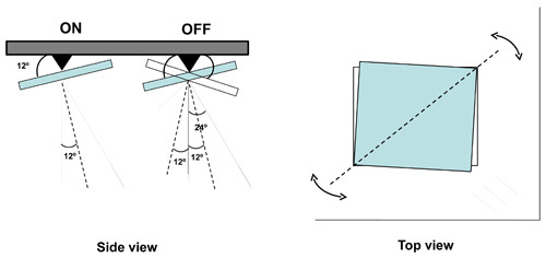 Figure 1. Operation of the micromirrors in the DMD. (Side view) Electrostatic forces directed at individual mirrors cause the mirror to be tilted in one of two possible orientations 12° from the horizontal. In the ON position an incident beam is directed along the optical axis perpendicular of the chip. In the OFF position the incident beam is directed 48° off axis. Light that hits the thin gaps between the mirrors is directed 24° off axis. (Top view) the tilt is oriented 45° with respect to the sides of the mirrors and chip.
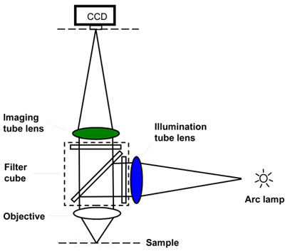 Figure 2. Basic layout of the modern fluorescent microscope. The filter cube is positioned in the "infinity space" between the objective and the tube lens. There is an imaging path that leads to the camera and there is an illumination path that brings the light to the sample. The tube lens for these two light path are typically different in design and in focal length. The illumination, but not the imaging, tube lens is designed for operation in the UV spectrum.
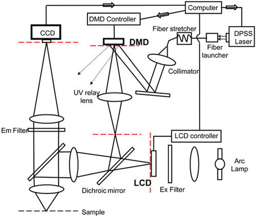 Figure 3. Layout for UV based DMD system. If the illumination is in the UV spectrum, then it must be brought through the tube lens that is corrected for UV. The tube lens in the imaging path is not designed for UV. A relay system is needed to create an easily accessible conjugate image plane. The different conjugate image planes in the microscope is marked by dotted red lines. Bright patterns in one image plane are projected in other conjugate planes. During imaging the pattern in the sample plane is projected onto the detector/camera. For illumination the pattern generated by the DMD is projected onto the sample.
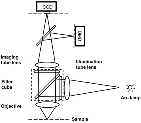 Figure 4. Layout for visible light DMD projection system. If the illumination light is in the visible range, it is possible to bring the DMD generated light pattern through the imaging light path. This can be easily implemented with commercial dual camera port attachments and the appropriate dichroic mirror.
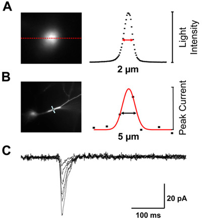 Figure 5. Lateral resolution of system. (A) Optical resolution on fluorescent target is ~2 μm. (B) Effective resolution as measured by photolysis of caged glutamate across a dendrite is ~5 μm. The increased distance is due to a combination of diffusion of glutamate and the finite width of the dendrite. (C) Photolysis can mimic the kinetics of synaptic events. The family of voltage clamped current responses is due to variations in the light energy delivered to the dendrite.
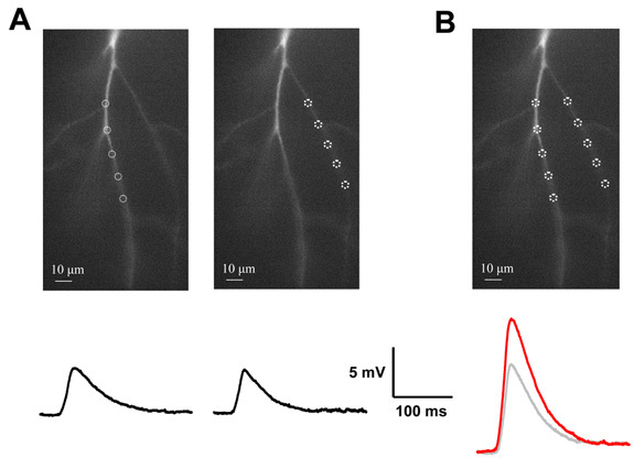 Figure 6. Non-linear summation across dendritic branch points. (A) Distributed inputs are applied to two dendritic branches separately. Their respective voltage responses are shown below. (B) The stimuli are then given simultaneously. The measured response (red trace) is different than the arithmetic sum of the two individual responses (grey trace).
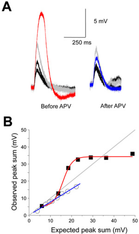 Figure 7. Supralinear summation is NMDA receptor dependent. (A) APV, a selective NMDA receptor antagonist blocks the supralinear summation. (B) The stimulus intensity relationship and its sensitivity to NMDA receptor antagonist is plotted.
Discussion
The advantage of DMD based photostimulation approach is most apparent for situations where the target occupies a relatively large area. If the target of interest is very small, such as a few dendritic spines, sequential scanning confocal and 2-photon systems are likely to be the better approach. One significant weakness of the DMD approach is its inefficient use of the available light. The bulk of the available light is necessarily directed to the OFF mirrors and not used.
The DMD based system is best suited for operation in the visible range. We anticipate DMD based photostimulation systems will make a significant impact when employed with optogenetics experiments.
Disclosures
No conflicts of interest declared.
Acknowledgments
This work was supported by a RO1 from NIH and Merit Reviews from the VA Research Service to C.-M. T., and an individual NRSA to C.W.L.
References
- Scanziani M, Hausser M. Electrophysiology in the age of light. Nature. 2009;461:930–939. doi: 10.1038/nature08540. [DOI] [PubMed] [Google Scholar]
- Tang C. Photolysis of caged neurotransmitters: Theory and procedures for light delivery. Curr. Prot. Neurosci. 2006:6.21.1–6.21.12. doi: 10.1002/0471142301.ns0621s37. [DOI] [PubMed] [Google Scholar]
- Nature Technology Feature, Cell imaging: Light activated. Nature. 2008;456:826–827. doi: 10.1038/456826a. [DOI] [PubMed] [Google Scholar]
- Lutz C, Otis TS, DeSars V, Charpak S, DeGregorio DA, Emiliani V. Holographic photolysis of caged neurotransmitters. Nature Methods. 2008;5:821–827. doi: 10.1038/nmeth.1241. [DOI] [PMC free article] [PubMed] [Google Scholar]
- Hornbeck LJ. Digital Light Processing and MEMs: An overview. Texas Instrument White Papers; [Google Scholar]


