

Abstract
Linear polarization intrinsic optical signal (LP-IOS) measurement can provide sensitive detection of neural activities in stimulus-activated neural tissues. However, the LP-IOS magnitude and signal-to-noise ratio (SNR) are highly correlated with the nerve orientation relative to the polarization plane of the incident light. Because of the complexity of orientation dependency, LP-IOS optimization and outcome interpretation are time consuming and complicated. In this study, we demonstrate the feasibility of circular polarization intrinsic optical signal (CP-IOS) measurement. Our theoretical modeling and experimental investigation indicate that CP-IOS magnitude and SNR are independent from the nerve orientation. Therefore, CP-IOS promises a practical method for polarization IOS imaging of complex neural systems.
Rapid scattering and polarization light changes have been observed in stimulus-activated neural tissues [1–4]. These stimulus-evoked fast intrinsic optical signals (IOSs), i.e., transient scattering and polarization changes, have time courses comparable to electrophysiological dynamics and, thus, promise a high-spatial- and high-temporal-resolution method for simultaneous examination of many neurons functioning together [5–9]. Because of the small magnitude of IOSs, system optimization of IOS recording is essential to provide necessary sensitivity and signal-to-noise ratio (SNR) to ensure reliable detection of stimulus-evoked neural activities.
Previous investigations have demonstrated that linear polarization IOS (LP-IOS) recording can provide 1 order of magnitude improvement compared to light scattering IOS measurement [4]. In the LP-IOS recording system [1–5,10], stimulus-evoked polarization responses were measured by sandwiching the nerve between a linear polarizer and an analyzer. LP-IOS recording was highly dependent on the orientation of the nerve relative to the polarization plane, i.e., the vibration plane of the electrical field, of the linearly polarized light [1,10]. Both LP-IOS magnitude and SNR could achieve peak values by placing the long axis of nerve axons at 45° relative to polarization plane of the linearly polarized light. Orientation optimization of the LP-IOS measurement is practical for simple nerve systems, such as isolated nerve axons [4,10,11]. However, in complex neural systems, such as the brain cortex or retinal tissue, neural axons and dendrites may have variable orientations. Therefore, LP-IOS imaging of complex neural networks is technically difficult.
In this study, we demonstrate the feasibility of using the circular polarizer and analyzer to achieve circular polarization IOS (CP-IOS) measurement of stimulus activated nerve axons. Our theoretical modeling and experiment verification indicate that CP-IOS magnitude and SNR are independent from nerve orientation and, thus, can provide a simple method for sensitive IOS measurement of neural systems with complex structures.
Figure 1 is a block diagram of the CP-IOS recording system. In order to simplify the description, we employed a model in which the nerve orientation was in the plane that was perpendicular to the optical axis of the recording system (Fig. 1). However, the CP-IOS measurement can generally work for other nerve orientations. In Fig. 1, the right-circular polarizer consists of linear polarizer LP1 and quarter-wave plate QWP1; the left-circular analyzer consists of another quarter-wave plate (QWP2) and linear polarizer LP2. Because of the orthogonal arrangement of the right-circular polarizer and left-circular analyzer, transient polarization IOS change in the stimulus-activated nerve bundle (NB) can be detected using a high-speed (10,000 Hz) photodiode (PD), as shown in Fig. 1.
Fig. 1.

Diagram of the experimental setup for CP-IOS recording. A near-IR (~830 nm) superluminescent laser diode (SLD-35-HP, Superlum) is used for light illumination. Lenses L1 and L2 are used to deliver and collect light, respectively. A right-circular polarizer, which consists of LP1 and QWP1, is used to produce clockwise polarization illumination of the NB (observer facing to the light propagation direction). The orientation of the long axis of nerve bundles relative to polarization plane of LP1 is indicated by α. The left-circular analyzer, which consists of QWP2 and LP2, is used to pass through anticlockwise polarization signals. A fast (10,000 Hz) PD is used for monitoring stimulus-evoked CP-IOS dynamics. The polarization planes of LP1 and LP2 are set at 0° and 90°, respectively, relative to the x axis. The fast axes of QWP1 and QWP2 are set at 45°, and −45°, respectively, relative to the x axis.
The polarization property of each optical part in Fig. 1 can be mathematically described by the Jones matrices. In the following equations, P1, Q1, Q2, and P2, are used to denote the Jones matrices of LP1, QWP1, QPW2 and LP2, respectively:
| (1) |
| (2) |
| (3) |
| (4) |
where R(θ) is the rotation matrix [12]:
| (5) |
If we assume that polarization IOS of the nerve is dominated by stimulus-evoked birefringence change [4,13,14], the nerve bundles can be considered a phase retarder. The Jones matrix of the nerve bundle can be modeled as
| (6) |
where α is the nerve angle relative to the x axis, and ψ is the phase difference between the long axis (x′ axis, Fig. 1) and the perpendicular axis (y′ axis, Fig. 1) of the nerve bundle due to the birefringence. R(α) is the rotation matrix defined by Eq. (5).
We assume that the electrical field of the linear polarized light is Ein = [Ex, Ey]T, where the superscript T denotes transpose operation, and Ex, and Ey are real values. The output electrical field can be modeled as
| (7) |
Therefore, the output irradiance of the CP-IOS measurement is
| (8) |
where * demotes the conjugate operation. As shown in Eq. (8), the output of the CP-IOS measurement is independent from α, which is the nerve orientation with respect to the x axis.
By ignoring QWP1 and QWP2 in the CP-IOS, the system shown in Fig. 1 can be simplified to a traditional LP-IOS recording system. For the LP-IOS recording system, the output electrical field can be modeled as
| (9) |
The output irradiance of the LP-IOS recording is [14]
| (10) |
Equation (10) indicates that the output irradiance of the LP-IOS recording is highly dependent on the nerve orientation α.
Lobster (Homarus americanus) leg nerve axons were employed as a simple nerve model for experimental verification of the CP-IOS measurement. The detailed procedure of the sample preparation has been reported in our previous publications [5,10]. Briefly, the Furusawa pulling out method was applied to extract the nerves [15]. The recording chamber was filled with Ringer’s solution. At the center of the chamber, a 1 mm × 3 mm transparent window was opened for transmitted IOS recording. A cover glass was placed on the top of the recording chamber to reduce the effect of water fluctuation on the recording stability. A pair of silver electrodes, ~10 mm away from the left edge of the recording window, were used to stimulate the nerve. Another pair of silver electrodes, ~10 mm away from the right edge of the imaging window, were used to record stimulus-evoked electro-physiological response of the nerve. Each stimulus pulse lasted for 0.1 ms, with current magnitude of ~2 mA. Each stimulus pulse corresponded to one individual recording trial, and repeated stimuli, at 1.5 s intervals, were used for averaging purposes to increase the SNR of the IOS measurement. For each recording trial, a 40 ms prestimulus and a 100 ms poststimulus measurement were continuously recorded with the PD system shown in Fig. 1. In the PD system, two recording channels, i.e., a DC channel with a 10 K Hz low-pass filter and an AC channel with a 1–10 K Hz bandpass filter, were used for dynamic measurements of the background light and dynamic light changes, respectively.
Figure 2 represents comparative measurements of the CP-IOS (dark traces in the left panel, Fig. 2) and LP-IOS (dark traces in the right panel, Fig. 2), with simultaneous electrophysiological recordings (gray traces in Fig. 2). In Fig. 2, the IOS and electrophysiological responses reached their magnitude peaks with comparable time courses. Therefore, the IOS could reliably track the stimulus-evoked neural activities. As shown in Fig. 2, the CP-IOS (left panel) magnitude had no obvious change with respect to variable α, while the LP-IOS magnitude (right panel) peaked at α = 45°, which was consistent with previously reported orientation dependency of the LP-IOS recording [1,10].
Fig. 2.
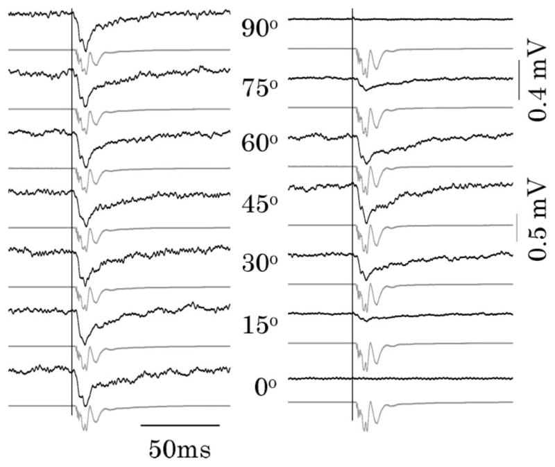
Left panel shows CP-IOSs (dark traces) and corresponding electrophysiological signals (gray traces) relative to α, which is the nerve orientation with respect to the x axis. Right panel shows CP-IOS responses (dark traces) and corresponding electrophysiological signals (gray traces) with respect to α. It is observed that the CP-IOS magnitude is independent from α. In contrast, the LP-IOS magnitude peaked at α = 45°. Vertical lines indicate the onset of stimulus. Each trace is an average of 150 recording passes. IOS magnitude is represented with units of millivolts, corresponding to the voltage output of the PD in Fig. 1. During the experiment, the light power after LP1 (Fig. 1) was constantly controlled at 1.0 mW for both CP-IOS and LP-IOS measurements.
Figure 3 shows quantitative comparisons of the CP-IOS and LP-IOS measurements. As shown in the left panel of Fig. 3, CP-IOS magnitudes (dark bars) had a relatively constant value (3.3–3.5 × 10⁻⁴ V) with nerve orientation α at 0°, 15°, 30°, 45°, 60°, 75°, and 90°. In contrast, LP-IOS peaked at 45° with magnitude of ~3.4 × 10⁻⁴ V), and degraded dramatically at other orientations. The peak value of CP-IOS at different nerve orientations was comparable to that of the LP-IOS peak recorded at α = 45°. The right panel of Fig. 3 represents the correlation coefficient, i.e., the similarity, between the CP-IOS and LP-IOS dynamics. The high correlation ratio (~0.92) indicates that CP-IOS and LP-IOS had comparable temporal dynamics, and implies that they might share identical signal source/mechanism associated with the stimulus-evoked neural activity.
Fig. 3.
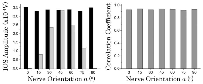
Left panel shows CP-IOS amplitude (dark bars) and LP-IOS amplitude (gray bars) as a function of the nerve orientation α. Right panel shows correlation rates between the CP-IOS (0°, 15°, 30°, 45°, 60°, 75° and 90°) and LP-IOS (45°) responses shown in Fig. 2.
In summary, we demonstrated robust CP-IOS recording of stimulus-evoked neural activity. Both theoretical analysis and an experimental test were conducted to compare the CP-IOS measurement and conventional LP-IOS recording. Our investigations indicated that the stimulus-evoked CP-IOS changes were free from the nerve orientation, but LP-IOS recording was highly dependent on the nerve orientation (Figs. 2 and 3). Moreover, at any given nerve orientation, the CP-IOS magnitude was comparable with the peak value of the LP-IOS with the nerve oriented at 45° (~3.4 × 10⁻⁴ V, left panel of Fig. 3). The high correlation ratio (~0.92) between the CP-IOS and LP-IOS dynamics suggested that they could equivalently reflect the stimulus-evoked neural activity. This equivalence can be theoretically explained by comparing Eqs. (8) and (10). By substituting α = 45° into Eq. (10), it can be simplified to
| (11) |
which is exactly identical to Eq. (8).
Because the CP-IOS recording is totally orientation free, highly sensitive imaging of the dynamic neural activities of complex neural systems will be possible. For traditional LP-IOS measurement, the IOS can be optimized by adjusting the nerve to 45° relative to polarization plane of the linear polarized light. This orientation adjustment is feasible for polarization measurement of isolated nerve bundles [1,10]. However, this simple strategy cannot work for complex neural systems, such as brain cortex or retina, that may consist of neurons in multiple directions. In principle, dynamic rotation of the linear polarizer and analyzer in the LP-IOS can be used for optimized imaging of selective neural groups, but it is a time-consuming procedure and simultaneous monitoring of many types of neurons functioning together is challenging. Our demonstrated CP-IOS system provides a simple method to compensate for orientation sensitivity of nerve systems. We anticipate that the CP-IOS can find important applications for simultaneous polarization imaging of many neurons working together in complex neural networks.
Acknowledgments
The authors thank Dr. Shuangyun Shao for help on this project. This research was supported in part by the Dana Foundation (Brain and Immuno-Imaging Grant Program) and the National Institutes of Health (NIH) (5R21RR025788-02 and 1R21EB012264-01A1).
References
- 1.Cohen LB, Keynes RD, Hille B. Nature. 1968;218:438. doi: 10.1038/218438a0. [DOI] [PubMed] [Google Scholar]
- 2.Tasaki I, Watanabe A, Sandlin R, Carnay L. Proc Natl Acad Sci USA. 1968;61:883. doi: 10.1073/pnas.61.3.883. [DOI] [PMC free article] [PubMed] [Google Scholar]
- 3.Landowne D. Jpn J Physiol. 1993;43:S7. [PubMed] [Google Scholar]
- 4.Carter KM, George JS, Rector DM. J Neurosci Methods. 2004;135:9. doi: 10.1016/j.jneumeth.2003.11.010. [DOI] [PubMed] [Google Scholar]
- 5.Schei JL, McCluskey MD, Foust AJ, Yao XC, Rector DM. NeuroImage. 2008;40:1034. doi: 10.1016/j.neuroimage.2007.12.055. [DOI] [PMC free article] [PubMed] [Google Scholar]
- 6.Schmoll T, Kolbitsch C, Leitgeb RA. J Biomed Opt. 2010;15:041513. doi: 10.1117/1.3463008. [DOI] [PubMed] [Google Scholar]
- 7.Li YC, Strang C, Amthor FR, Liu L, Li YG, Zhang QX, Keyser K, Yao XC. Opt Lett. 2010;35:1810. doi: 10.1364/OL.35.001810. [DOI] [PMC free article] [PubMed] [Google Scholar]
- 8.Yao XC, George JS. NeuroImage. 2006;33:898. doi: 10.1016/j.neuroimage.2006.06.060. [DOI] [PubMed] [Google Scholar]
- 9.Yao XC, Zhao YB. Opt Express. 2008;16:12446. doi: 10.1364/oe.16.012446. [DOI] [PubMed] [Google Scholar]
- 10.Yao XC, Foust A, Rector DM, Barrowes B, George JS. Biophys J. 2005;88:4170. doi: 10.1529/biophysj.104.052506. [DOI] [PMC free article] [PubMed] [Google Scholar]
- 11.Tasaki I, Byrne PM. Jpn J Physiol. 1993;43:S67. [PubMed] [Google Scholar]
- 12.Jones RC. J Opt Soc Am. 1941;31:488. [Google Scholar]
- 13.Foust AJ, Beiu RM, Rector DM. Appl Opt. 2005;44:2008. doi: 10.1364/ao.44.002008. [DOI] [PubMed] [Google Scholar]
- 14.Cohen LB, Hille B, Keynes RD. J Physiol. 1970;211:495. doi: 10.1113/jphysiol.1970.sp009289. [DOI] [PMC free article] [PubMed] [Google Scholar]
- 15.Furusawa K. J Physiol. 1929;67:325. doi: 10.1113/jphysiol.1929.sp002573. [DOI] [PMC free article] [PubMed] [Google Scholar]