Abstract
A novel approach to constructing robots is based on concentrically combining pre-curved elastic tubes. By rotating and extending the tubes with respect to each other, their curvatures interact elastically to position and orient the robot's tip, as well as to control the robot's shape along its length. Since these robots form slender curves, they are well suited for minimally invasive medical procedures. A substantial challenge to their practical use is the real-time solution of their kinematics that are described by differential equations with split boundary equations. This paper proposes a numerically efficient approach to real-time position control. It is shown that the forward kinematics are smooth functions that can be pre-computed and accurately approximated using Fourier series. The inverse kinematics can be solved in real time using root finding applied to the functional approximation. Experimental demonstration of real-time position control using this approach is also described.
I. Introduction
Minimally invasive medical procedures involve the manipulation of tools, sensors and prosthetic devices inside the body while minimizing damage to surrounding tissue structures. In many cases, navigation to the surgical site involves steering the instrument along three-dimensional curves through tissue to avoid bony or sensitive structures (percutaneous procedures), or following the interior contours of a body orifice (e.g., the nasal passages) or body cavity (e.g., the heart). Once at the surgical site, it is often necessary to control the position and orientation of the instrument's distal tip while holding relatively immobile the proximal inserted length.
The instruments used in minimally invasive procedures can be grouped into three general categories. The first category includes straight flexible needles that are used for percutaneous procedures in solid tissue. Needle steering along a curved insertion path is achieved by applying lateral forces at the needle base or tip that cause it to flex as it is advanced into the tissue. Consequently, these instruments possess no ability to produce lateral tip motion without further penetration into solid tissue.
The second category of instruments is composed of a straight, stiff shaft with an articulated tip-mounted tool and is in common use for minimally invasive access of body cavities (e.g., chest or abdomen) [1]. The shaft must follow a straight-line path from the entry point of the body to the surgical site. Lateral motion of the tip depends on pivoting the straight shaft about a fulcrum typically located at the insertion point into the body.
The third category of instruments includes elongated, steerable devices, such as multi-stage micro-robot devices, [2], [3] and steerable catheters [4],[5]. Multi-stage micro-robot devices are typically sufficiently rigid to support their own weight as well as to apply appreciable lateral forces to the surrounding tissue. Since the steerable length is modest, however, these devices are often mounted at the distal end of a rigid shaft. Similarly, only the distal portion of catheters is steerable, however, their proximal length is of sufficient flexibility so as to conform to the curvature of the vessel through which it is advanced. An alternate novel technology enables extension along an arbitrary 3D curve [3]. This technology is, however, nonholonomic in that lateral motion of the tip is only accomplished in combination with tangential motion.
Concentric tube robots possess the best properties of all three types of instruments. With cross sections comparable to needles and catheters, they are nevertheless capable of substantial actively-controlled lateral motion and force application along their entire length. Since robot shape can be controlled, they enable navigation through the body along 3D curves. Furthermore, the lumen of the tubes can house additional tubes and wires for controlling articulated tip-mounted tools. An example is shown in Fig. 1.
Fig. 1.
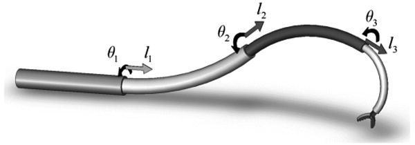
Concentric tube robot comprised of four telescoping sections that can be rotated and translated with respect to each other.
Thus, this technology holds the potential for enabling many new and exciting minimally invasive interventions. An important class of applications for such a device would be to enter a body lumen by steering along a curved path through tissue or through a body orifice. Once inside the lumen, the proximal portion can remain relatively fixed while the distal portion manipulates tools within the lumen to perform minimally invasive surgery.
The kinematic modeling for real-time control of these robots is challenging in comparison to that of traditional robots whose links are relatively rigid and whose joints are discrete. The forward kinematics can be cast as a 3D beam-bending problem in which the kinematic input variables (tube rotations and displacements at the proximal end) enter the problem as a subset of the boundary conditions. The remaining boundary conditions are comprised of point forces and torques applied to the distal ends of the tubes. Contact along the robot's length (e.g., with tissue) generates additional distributed and point loads.
Thus, it can be anticipated that the most general kinematic model can be expressed as a two-point boundary value problem involving a differential equation with respect to arc length along the common centerline of the tubes. Phenomena that may be included in the model are bending, torsion, friction, shear, axial elongation and nonlinear constitutive behavior.
Since real-time control necessitates balancing accuracy of the model with efficiency of its computation, the first kinematic models developed treated the curved portions of the tubes as torsionally rigid [6]-[11]. The torsionally rigid model, first derived in [6], results in an algebraic expression for curvature of the combined tubes that can be analytically integrated to yield position and orientation of the robot's tip. The resulting forward kinematic model is also algebraic and can thus be computed quickly.
Closed form inverse kinematic solutions only exist for very simple concentric tube robots [8]. Jacobian-based inverse kinematics using the algebraic curvature model were first formulated in [8] and experimentally implemented in a teleoperation system in [9]. Despite error in the kinematic model, position control of the slave was possible since the human operator visually closes a feedback loop on position error.
Despite its computational efficiency, this approach is not, however, amenable to achieving smooth, high-bandwidth performance. Toward this end, a forward kinematic model and Jacobian matrix were formulated that includes torsion in the straight proximal portions (transmission lengths) of the tubes, but treats the curved portions as torsionally rigid [7],[11]. With this model, each computation of the forward model and Jacobian involves solving a root-finding problem for the torsional twist in each of the tubes' transmission lengths. This approach can appreciably reduce modeling error for robot designs with long transmission lengths at the computational cost of real-time root finding.
The most recent forward kinematic models for concentric tube robots include torsional compliance along the entire length of the constituent tubes [12]-[14]. This work also demonstrates experimentally that the predicted twisting in the curved portions of the tubes does occur and can be substantial [12],[14]. While providing significantly improved accuracy over earlier models, these new models are, as anticipated, considerably more complex.
They consist of second-order differential equations with split boundary conditions. Furthermore, integration of these equations yields curvature as a function of arc length. To solve for the robot tip frame relative to the base, curvature must be integrated along the arc length once more to yield tip frame orientation and a second time to obtain tip frame position.
The computational difference between the various forward kinematic models can be summarized as follows. Solution of the torsionally rigid model involves evaluating algebraic expressions. This is comparable to the kinematics of standard open-chain robots comprised of rigid links and discrete joints. Including torsional compliance in the straight transmission lengths of the tubes converts the computation to an algebraic root finding problem. Finally, including torsional compliance in the curved portions of the tubes converts the algebraic root finding problem to root finding on the (numerically computed) solution of second-order differential equations followed by the additional integrations needed to compute position and orientation.
The contribution of this paper is to provide a framework that enables real-time position control using the kinematic models incorporating torsional compliance along the entire length of the tubes. The paper is arranged as follows. Section II summarizes the torsionally compliant model. Section III describes the proposed approach in which the forward kinematic solution is pre-computed over the robot's workspace and approximated by a product of truncated Fourier series. The inverse kinematic solution is solved at each time step using a root finding method applied to the functional approximation. Experimental implementation of closed-loop position control is described in Section IV and conclusions are presented in Section V.
II. Kinematic Modeling
This section summarizes the model of [12] that includes bending and torsion for an arbitrary number of tubes whose curvature and stiffness can vary with arc length. Effects that are neglected include shear of the cross section, axial elongation, nonlinear constitutive behavior, friction between the tubes and deformation due to external loading. Note that these effects are neglected, but not necessarily negligible. For example, deformation due to external loads during environment interaction is an important topic that we are also considering [15].
In the remainder of the paper, subscript indices, i = 1, 2,…, n, are used to refer to individual tubes with tube 1 being outermost and tube n being innermost. Arc length, s, is measured such that s = 0 at the proximal end of the tubes. The total length of each tube is designated by Li.
As shown in Fig. 2, material coordinate frames for each cross section can be defined as a function of arc length s along tube i by defining a single frame at the proximal end, Fi(0), such that its z axis is tangent to the tube's centerline. Under the unrestrictive assumption that the tubes do not possess initial material torsion, the frame, Fi(s), is obtained by sliding Fi(0) along the tube centerline without rotation about its z axis (i.e., a Bishop frame [16]). As the tubes move, bend and twist, these material frames act as body frames tracking the displacements of their cross sections. It is also useful to define a reference frame, F0(s), which displaces with the cross sections, but does not rotate about its z axis.
Fig. 2.
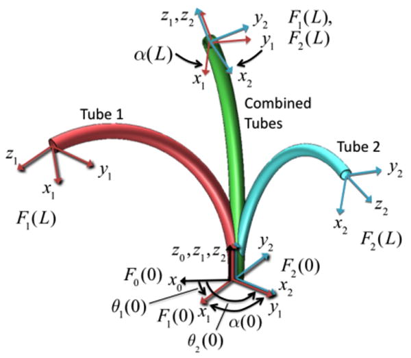
Tube coordinate frames are denoted Fi(s). The relative z-axis twist angle between tube frames 1 and 2 is α2 (s). Due to torsional twisting, it varies from a maximum α2 (0) at the base to a minimum α2 (L) at the tip.
As the ith tube's coordinate frame Fi(s) slides down its centerline, it experiences a body-frame angular rate of change per unit arc length given by
| (1) |
in which (uix, uiy) are the components of curvature due to bending and uiz = 0 is the curvature component due to torsion.
The kinematic input variables consist of the rotation and translation of each tube about and along the common centerline of the combined tubes. The rotation angle, θi(s), is defined as the z -axis rotation angle from frame F0(s) to frame Fi(s). The translation variable, li, is defined as the arc length distance from frame F0(0) to the initially coincident frame Fi(0). Elastic interaction of the tubes is a function of relative rotation angles of the tubes so these are also defined as
| (2) |
The forward kinematic equations for n tubes of arbitrary stiffness and initial curvature can be written in terms of 2n − 2 state variables {αi, uiz}, i = 2,…, n as [12]
| (3) |
In these equations, kixy and kiz are the bending and torsional stiffnesses, respectively, of the ith tube. A circumflex on a curvature component is used to designate the initial pre-curvature of a tube. Rz(αj) is the rotation matrix for a rotation of angle αj about the z axis. Also, ui∣x,y denotes the x and y components of the vector.
Half of the boundary conditions for this equation are obtained from the kinematic input variables, θi(0)
| (4) |
The remaining boundary conditions are defined by the torque applied at the distal ends of the tubes. Assuming no external torque, the torsional bending moment and thus curvature are zero at this location,
| (5) |
Equations (3)-(5) are easily applied to any combination of pre-curved tubes. The stiffness and pre-curvature of each tube can be an arbitrary function of arc length – even discontinuous. Consequently, there is no need to subdivide the domain during integration over a telescoping arrangement of tubes. Distal to the physical end of each tube, its stiffness and curvature can be defined as zero. Details of the numerical solution are presented below.
III. Closed-loop Position Control
Tool-frame position control involves solving the forward and inverse kinematic problems at real-time rates. The forward kinematic model (3)-(5) presents a challenge in this regard since it is a nonlinear second-order differential equation with split boundary conditions. Furthermore, these equations yield curvature as a function of arc length. Curvature must be integrated once more to yield tip frame orientation and a second time to obtain tip frame position.
To achieve a real-time implementation, the approach taken here is to pre-compute the model's forward kinematic solution over the robot's workspace and then to approximate it by a product of truncated Fourier series. The inverse kinematic solution is solved at each time step using a root finding method applied to the functional approximation. These techniques are described in the following subsections.
A. Forward Kinematic Functional Approximation
For solving (3)-(5), we note that robot shape is independent of rigid body translation and rotation. Since rotation or translation of all tubes simultaneously produces rigid body motion, the number of independent kinematic inputs can be reduced by two. Given the form of (3), we choose the rotation and translation of the first tube, θ1 and l1, as references for measuring all tubes' angles and linear displacements. Thus, the reduced set of kinematic input variables is {α2-n (0),l2-n} = {αi(0),li}, i = 2,…, n and the desired output is the tip frame position and orientation relative to the base, g1 (α2-n (0),l2-n). Here, the subscript 1 indicates that the displacement is for the reference values of θ1 = l1 = 0. The transformation for nonzero values is given by
| (6) |
To pre-compute the forward kinematic solution over a grid of kinematic input values, it is convenient to define the grid at the robot's tip in terms of {αi (L),li}, i = 2,…,n and so solve (3) and (5) as an initial value problem by integrating backward in arc length from L to 0. This yields the curvature along the robot as well as the input twist angles, αi (0), i = 2,…,n. Curvature can then be integrated along the robot's length to yield tip position and orientation relative to the base, g1(α(0),l) as defined above. Integrating curvature is analogous to integrating body frame twist velocity. A variety of numerical integration methods are available that preserve group structure on SE(3) [17],[18].
A dense discretization of {α2-n(0),l2-n} yields a large data set of g1(α2-n (0),l2-n). While one approach is to store this data as a lookup table, functional approximations offer reduced storage requirements at modest computational cost. Since the input variables have a periodic effect on the tip frame, each of the tip frame coordinates can be modeled using a product of truncated Fourier series.
Define a scalar Fourier series H of order q as
| (7) |
in which cj ∈ ℂ, and asterisk indicates complex conjugate. We model each of the tip coordinates in p1 =[x1, y1, z1]T using a product of series in the form of (7). For example, assuming n tubes that can be rotated and translated and using the same order series for all input variables, x1 is of the form
| (8) |
in which the linear displacement variables, li, are scaled by appropriate wavelength variables, λi.
Tip orientation can be modeled in a similar fashion. For example, for the five degree of freedom robot used in the experiments, roll angle is undefined and a tangent vector can define orientation, t1 = [tx1, ty1, tz1]T, with components modeled by (8).
Multiplying out the product expansion for each component of tip position and direction produces sets of unknown constant coefficients that can be estimated using linear least squares from the data set g1(α2-n (0),l2-n). The resulting approximation is denoted as g̃1(α2-n (0),l2-n) and it can be used in (6) to produce the approximated forward kinematic solution, g̃0(α2-n(0), l2-n,θ1,s1).
B. Real-time Inverse Kinematics
Given the desired tip frame , the inverse kinematics problem can be posed as a root finding problem. The desired joint values correspond to the zero of a scalar- or vector-valued function, , representing the distance between the actual and desired tip frames. One example of is the twist vector corresponding to the screw motion between g̃0 and . In this context, the standard Jacobian inverse approach is an on-line implementation of Newton's root finding method.
For the five degree of freedom robot used in the experimental implementation described below, tip frame roll angle is undefined and so the function is selected as
| (9) |
Here, tip position is given by p0 and tip tangent direction by unit vector t0. The scaling factor γ is given by the ratio of maximum tip position error to maximum orientation angle error,
| (10) |
Root finding is accomplished using the Gauss-Newton method. The method requires the Jacobian of (9) with respect to the joint variables. This can be evaluated numerically using additional function evaluations of (9) or computed from the analytic form of the Jacobian. The latter is easily obtained since the partial derivatives of (8) with respect to the joint variables have the same functional form as (8).
The number of iterations needed to converge to the inverse solution depends on the initial magnitude of (9). In teleoperation, the current joint values and tip location can be used to initiate root finding for the next time step. Thus, the maximum magnitude is usually small and can be estimated from the desired tip motion bandwidth and controller cycle time. For example, a 10 mm amplitude sinusoidal tip displacement at 10 Hz has a maximum displacement of less than 1 mm during a 1 kHz control cycle. Consequently, the algorithm typically converges within a controller time step. For those cases when convergence is not obtained within a control cycle, motion is still well behaved since the implementation is such that error decreases with each iteration. As described below, our current unoptimized implementation can compute up to eight iterations during the 1 msec time step of our 1 kHz controller.
IV. Experiments
To demonstrate real-time position control using the approach described above, a teleoperation system using the robot shown in Fig. 3 and Fig. 4 was implemented using the controller shown in Fig. 5. The system includes a master arm comprised of a PHANTOM Omni haptic device (Sensable Technologies, Inc.), a slave arm consisting of the concentric tube robot, and master and slave controllers. The robot consists of the three NiTi tubes shown in Fig. 4 and possesses five degrees of freedom. The tubes comprising the outer pair are of almost equal stiffness and are translated as pair. Thus, they form a section of variable curvature with kinematic input variables consisting of tube rotation angles, θ1, θ2, and a single translation variable for the pair, l1 = l2. The innermost tube is much less stiff than the outer pair such that the portion of its length retracted inside the outer pair conforms to the curvature of the pair. Its kinematic variables are θ3,l3. The five kinematic inputs are used to control the robot's tip position and tangent direction.
Fig. 3.
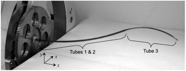
Three-tube concentric tube robot.
Fig. 4.
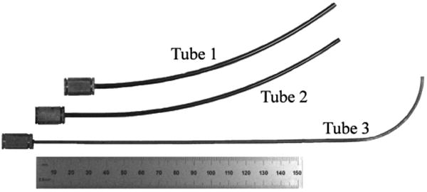
Tubes comprising the robot. Tubes 1 and 2 form a variable curvature balanced pair that dominate tube 3. Ruler shows units in mm.
Fig. 5.
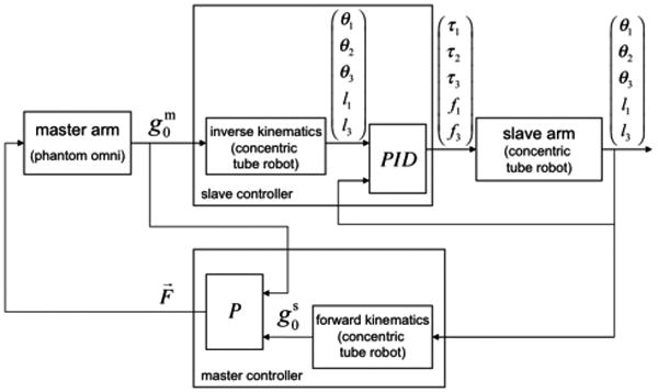
Teleoperator block diagram.
The properties of the tubes are given in Table 1. To solve the forward kinematics, (3) requires the ratio of bending to torsional stiffness for each tube as well as the relative stiffness of the tubes. For linear elastic tubes, the former is given by 1+ν and was computed using a value of ν = 0.3.
Table 1.
Tube Parameters.
| Tube | 1 | 2 | 3 |
|---|---|---|---|
| Outer Diameter (mm) | 2.77+/-0.01 | 2.41+/-0.01 | 1.85+/-0.01 |
| Inner Diameter (mm) | 2.55+/-0.01 | 1.97+/-0.01 | 1.65+/-0.01 |
| Sections of constant pre-curvature listed base to tip (length, mm; radius, mm) | (l=150; r=242) | (l=18; r= ∞) (l=150; r=260) |
(l=186; r= ∞) (l=57; r=35) |
| Calibrated stiffness (relative to Tube 1) | 1 | 1.53 | 0.21 (straight) 0.07 (curved) |
| Maximum % strain to straighten curved section | 0.57 | 0.46 | 2.64 |
Given that the tubes are of the same alloy and were processed similarly, the relative stiffness of the tubes should be computable as the ratio of moments of inertia. Stacking the tolerances for inner and outer diameters of tube pairs, however, produces large variations in stiffness ratio. Instead, calibrated stiffness ratios were computed by measuring the individual tube pre-curvatures and the pair-wise combined curvature for αi(s) = π using a camera measurement system (Vision Appliance, Dalsa, Inc.). Using this approach, it was observed that the curved section of Tube 3 was a third of the stiffness of the straight portion. This observation is in agreement with the flattening of the stress-strain curve that occurs for NiTi alloys at strains greater than 1%.
In Fig. 5, the slave controller receives the position and tangent direction of the tip of the master arm (represented by ) and calculates the inverse kinematics of the concentric tube robot using the method described in the preceding section. Then, a set of PID controllers calculate the torques/forces applied to the joints of the robot. The master controller reads the joint configuration of the robot and calculates the position and direction of its tip. The force feedback provided to the master is governed by a proportional control law based on the Cartesian position error between the master and slave tip positions.
The teleoperator system of Fig. 5 is implemented by a multi-thread process under Windows 2000. While Windows 2000 does not natively support hard real-time scheduling, it does support soft real-time scheduling with a time-critical thread priority. When used appropriately, a time-critical thread may be used to maintain a regular 1 kHz update rate with sufficiently low timing variations to be used for closed-loop control. For this particular controller, the slave mechanism bandwidth is less than 10 Hz, so soft real-time implementation of a 1 Khz control loop was more than sufficient.
The process includes two time-critical user mode threads running at 1 kHz that implement the controllers and an application thread that updates a GUI (not shown). One of the time-critical threads executes the PID controller of the slave arm and the other executes the master controller and inverse kinematics block of the slave controller. The separation of threads eases integration between the master with its IEEE-1394 based interface and the slave controlled through a Quanser Q8 data acquisition board with its realtime IO subsystem support accessed through the HIL SDK.
A. Forward Kinematic Model
The method of section III.A was used to arrive at a functional approximation of the forward kinematic model. Removing the rigid body degrees of freedom, the reduced set of kinematic input variables is given by {α2, α3, l3}. Solving (3) and (5) as an initial value problem, the resulting curvature was integrated backward in arc length from L to 0 to get g1(α2(0),α3(0),l3) for a uniform 40×40×40 grid of {α2(L),α3(L),l3}. As an example, the position coordinate x1 is plotted as a function of α2 and α3 for a fixed value of l3 in Fig. 6. It can be seen that the coordinate is a smooth, periodic function of the inputs.
Fig. 6.
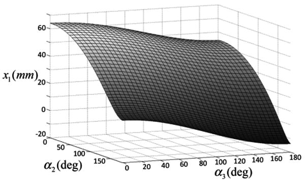
Model computed tip position coordinate x1 as a function of α2 and α3 for l3 = 20.5 mm.
This data set was used to construct a second-order product series (8) for each component of position vector p1 and direction vector t1 using a wavelength of . The resulting functional approximations, each defined by 125 constant coefficients, were evaluated against a second data set constructed using grid values midway between those of the original set. In this evaluation, the average tip position error was 0.025 mm (0.1 mm maximum) and the average tip direction error 0.02 degrees (0.06 degrees maximum). This approximation error is insignificant in comparison to a modeling error of several mm and degrees [12]. Furthermore, it is a fraction of the desired model error of 1 mm and 5 degrees that is suitable for many clinical applications.
B. Inverse Kinematic Model
Inverse kinematics were implemented as described in section III.B. Tube lengths and pre-curvatures limit maximum tip position and orientation errors over the entire workspace to approximately 200 mm and π radians, respectively. For convenience of interpretation, the scaling factor of γ = (180 mm) / (π rad) was selected yielding a tangent error magnitude in degrees.
Our current unoptimized implementation of the Gauss-Newton method can perform eight iterations in 0.5 msec, however, convergence to the accuracy of the functional approximation is usually achieved in five or fewer iterations. This fits easily within the 1 msec cycle time of our controller.
In addition, the inverse kinematic implementation enforces continuity of the inverse solution and enforces joint limits on the tube extension variables, l1 = l2 and l3.
C. Demonstration Task
Performance of the teleoperation system was evaluated for a task that consisted of touching a sequence of nine 2 mm diameter beads embedded in the faces of three dodecahedral dice suspended on posts as shown in Fig. 7. This task requires the operator to control both the tip position and tangent direction to contact the beads. As shown in the accompanying video, teleoperation is smooth and responsive.
Fig. 7.
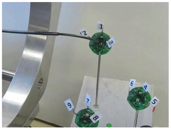
Teleoperated real-time position control task. Touching sequence of nine silver beads embedded in dice involves controlling both position and tangent direction of robot tip.
Since the inverse kinematic model converges within a single time step, any trajectory following error is due to two factors: kinematic modeling error and electromechanically-imposed bandwidth limitations. Steady state control error is due only to modeling error.
V. Conclusions
Concentric tube robots are a novel technology that has broad potential in minimally invasive surgery. While the most recently proposed and most accurate kinematic models are two-point boundary value differential equations, the solutions are smooth periodic functions that permit accurate approximation. This property is exploited and combined with an on-line root finding method for implementing realtime position control. Unoptimized control code running on a PC was easily able to compute the three-tube inverse kinematic solution at 1 kHz rate. Thus, both analytically and numerically, the approach provides the capacity for extension to robots with greater numbers of tubes. It can also be easily adapted to future kinematic models that include currently neglected effects such as friction and nonlinear constitutive behavior.
Acknowledgments
This work was supported by the National Institutes of Health under grants R01HL073647 and R01HL087797 and by the Wallace H. Coulter Foundation.
Contributor Information
Pierre E. Dupont, Email: pierre@bu.edu, Mechanical Engineering, Boston University, Boston, MA 02215 USA (phone: 617-353-9596; fax: 617-353-5866.
Jesse Lock, Email: lockj@bu.edu, Biomedical Engineering, Boston University, Boston, MA 02215 USA.
Brandon Itkowitz, Email: bitkowitz@gmail.com, Electrical and Computer Systems Engineering, Boston University, Boston, MA 02215 USA.
References
- 1.Madhanir A, Niemeyer G, Salisbury JK., Jr The Black Falcon: A Teleoperated Surgical Instrument for Minimally Invasive Surgery. IEEE/RSJ Int Conference on Intelligent Robots and Systems; Victoria, B.C., Canada. 1998. pp. 936–944. [Google Scholar]
- 2.Xu K, Simaan N. An Investigation of the Intrinsic Force Sensing Capabilities of Continuum Robots. IEEE Trans Robotics. 2008;24(3):576–587. [Google Scholar]
- 3.Degani A, Choset H, Wolf A, Zenati M. Highly Articulated Robotic Probe for Minimally Invasive Surgery. IEEE Int Conf on Robotics & Automation; Orlando. 2006. pp. 4167–4172. [DOI] [PMC free article] [PubMed] [Google Scholar]
- 4.Camarillo D, Milne C, Carlson C, Zinn M, Salisbury JK. Mechanics Modeling of Tendon-Driven Continuum Manipulators. IEEE Trans Robotics. 2008 Dec;24(6):1262–1273. [Google Scholar]
- 5.Meeker DC, Maslen EH, Ritter RC, Creighton FM. Optimal realization of arbitrary forces in a magnetic stereotaxis system. IEEE Trans on Magnetics. 1996 Mar;32(2):320–328. [Google Scholar]
- 6.Sears P, Dupont P. A Steerable Needle Technology Using Curved Concentric Tubes. IEEE/RSJ Int Conference on Intelligent Robots and Systems; Beijing. 2006. pp. 2850–2856. [Google Scholar]
- 7.Webster RJ, Okamura AM, Cowan NJ. Toward Active Cannulas: Miniature Snake-Like Surgical Robots. IEEE/RSJ Int Conference on Intelligent Robots and Systems; Beijing. 2006. pp. 2857–2863. [Google Scholar]
- 8.Sears P, Dupont PE. Inverse Kinematics of Concentric Tube Steerable Needles. IEEE International Conference on Robotics and Automation; Roma, Italy. 2007. pp. 1887–1892. [DOI] [PMC free article] [PubMed] [Google Scholar]
- 9.Itkowitz B. MS Thesis, Electrical & Computer Engineering. Boston Univ.; Boston, MA: 2007. Teleoperation of Concentric Tube Manipulators. [Google Scholar]
- 10.Webster RJ, III, Romano JM, Cowan NJ. Kinematics and Calibration of Active Cannulas. IEEE International Conference on Robotics and Automation; 2008. pp. 3888–3895. [Google Scholar]
- 11.Webster RJ, III, Swensen JP, Romano JM, Cowan NJ. Closed-Form Differential Kinematics for Concentric-Tube Continuum Robots with Application to Visual Servoing. 11th International Symposium on Experimental Robotics; Athens, Greece. 2008. [Google Scholar]
- 12.Dupont PE, Lock J, Butler E. Torsional Kinematic Model for Concentric Tube Robots. IEEE Int Conf on Robotics & Automation; Kobe, Japan. 2009. pp. 3851–58. [DOI] [PMC free article] [PubMed] [Google Scholar]
- 13.Rucker DC, Webster RJ., III Mechanics of Bending, Torsion, and Variable Precurvature in Multi-Tube Active Cannulas. IEEE Int. Conf. on Robotics & Automation; Kobe, Japan. 2009. pp. 2533–37. [Google Scholar]
- 14.Dupont PE, Lock J, Itkowitz B, Butler E. Design and Control of Concentric Tube Robots. IEEE Trans Robotics. 2010;26(2) doi: 10.1109/TRO.2009.2035740. [DOI] [PMC free article] [PubMed] [Google Scholar]
- 15.Mahvash M, Dupont P. Stiffness Control of Surgical Continuum Manipulators. IEEE Trans Robotics. doi: 10.1109/TRO.2011.2105410. in review. [DOI] [PMC free article] [PubMed] [Google Scholar]
- 16.Bishop RL. There is More than One Way to Frame a Curve. The American Mathematical Monthly. 1975 March;82(3):246–251. [Google Scholar]
- 17.Crouch PE, Grossman R. Numerical integration of ordinary differential equations on manifolds. Journal of Nonlinear Science. 1993;3(1):1–33. [Google Scholar]
- 18.Park J, Chung WK. Geometric integration on Euclidean group with application to articulated multibody systems. IEEE Trans Robotics. 2005;21(5):850–863. [Google Scholar]


