Abstract
Graphene oxide is promising as a plate-like giant molecular building block for the assembly of new carbon materials. Its water dispersibility, liquid crystallinity, and ease of reduction offer advantages over other carbon precursors if its fundamental assembly rules can be identified. This article shows that graphene oxide sheets of known lateral dimension form nematic liquid crystal phases with transition points in agreement with the Onsager hard-plate theory. The liquid crystal phases can be systematic ordered into defined supramolecular patterns using surface anchoring, complex fluid flow, and micro-confinement. Graphene oxide is seen to exhibit homeotropic surface anchoring at interfaces driven by excluded volume entropy and by adsorption enthalpy associated with its partially hydrophobic basal planes. Surprisingly, some of the surface-ordered graphene oxide phases dry into graphene oxide solids that undergo a dramatic anisotropic swelling upon rehydration to recover their initial size and shape. This behavior is shown to be a unique hydration-responsive folding and unfolding transition. During drying, surface tension forces acting parallel to the layer planes cause a buckling instability that stores elastic energy in accordion-folded structures in the dry solid. Subsequent water infiltration reduces interlayer frictional forces and triggers release of the stored elastic energy in the form of dramatic unidirectional expansion. We explain the folding/unfolding phenomena by quantitative nanomechanics, and introduce the potential of liquid crystal-derived graphene oxide phases as new stimuli-response materials.
Keywords: graphene oxide, liquid crystal, nematic, assembly, surface anchoring, folding, unfolding
Graphene oxide (GO) has received significant attention as an intermediate in the synthesis of monolayer graphene for electronics applications.1,2,3 Reduction of GO to high-quality graphene is challenging due to defect creation,4 but GO is an interesting material in its own right, and is attractive as a giant molecular building block for a variety of new carbon materials.1,5 Interest is growing in the applications of GO and reduced GO6,7 as barriers and fillers,8 sorbents,9 hydrogels,10 surfactants,11,12 and multilayer papers.13 The fundamental colloidal assembly rules for GO as a water-dispersible5,14 giant molecular plate are only beginning to be explored. Recently liquid crystalline phases have been observed in GO aqueous dispersions15,16 and in graphene strong acid solutions.17 We became interested in using GO liquid crystal phases to make new carbon materials by self-assembly and reductive annealing, as has been done with other carbon-atom-rich liquid crystalline systems.18,19,20 Liquid crystal phases offer a route to long-range order, and can be manipulated through flows, fields, surfaces, and micro-confinement to produce well-defined equilibrium assemblies that can be thermally converted into carbon materials with precise control of graphene layer structure.18,19,20 Here we investigate the fundamental assembly rules specific to GO as a liquid crystalline system, focusing on surface anchoring, complex fluid flow and micro-confinement. Some of the new ordered GO phases we create with these methods are observed to undergo drying and rehydration cycles, in which the GO layers fold and unfold to give unique anisotropic swelling behaviors. This hydration-responsive folding and unfolding is described in detail and opens the potential for liquid crystal-derived GO phases as smart stimuli-response materials.
RESULTS AND DISCUSSION
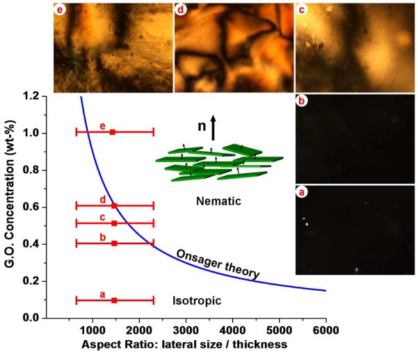
We began by studying the structure of GO suspensions during drying. Kim and coworkers15 recently observed spontaneous phase separation in GO through long-time sedimentation, leading to an isotropic top phase and a nematic liquid crystalline bottom phase. We attempted to make single-phase nematic GO by evaporative concentration starting from stable dilute GO suspensions (1 mg/ml). We observed that simple evaporation does not lead to bulk liquid crystals, but rather produces GO surface films at the liquid-gas interface,11 which increase in thickness as drying proceeds (Supplementary Fig. 2). Centrifugal vacuum evaporation, in contrast, is very effective at producing homogeneous liquid crystal phases (Fig. 1) as it prevents interfacial accumulation by driving GO away from the drying front. At approximately 0.5 wt-% there is a transition from the disordered isotropic liquid phase to an ordered phase with Schlieren textures characteristic of nematic liquid crystals (Fig. 1c,d,e). These textures are similar to those reported recently15,16 and contain disclinations of various strength as revealed by rotation of crossed polars.15,16 Near the transition, the textures are somewhat diffuse, which has been reported to indicate biphasic behavior associated with polydispersity in the GO layer population,16 and at the higher concentrations in Fig. 1 the textures become quite well defined indicating a homogeneous nematic phase.16 To produce a quantitative phase diagram (Fig. 1a), we measured the distribution of GO flake lateral sizes (Supplementary Fig. 1), defined as the diameter of a circle having the same area as the GO sheet determined by digital image analysis, and found reasonable agreement with the Onsager model of lyotropic liquid crystals in the disk formulation:21
| (1) |
where d and l are the lateral size and thickness of GO sheets respectively, ρ is the true material density, C is the concentration at isotropic-nematic phase transition.
Figure 1. Graphene oxide liquid crystal phase diagram.
Images are optical micrographs of bulk GO aqueous phases under crossed polarizers. Images show characteristic nematic phase Schlieren textures at GO concentrations greater than about 0.4 wt-%. Plot shows the nematic-isotropic transition predicted by the Onsager model using the hard disk formulation21 of d/l ≈ 5σGO/(σsuspensionC). The measured transition concentrations are in reasonable agreement with the Onsager prediction. Calculation of aspect ratio is based on lateral size distributions measured from SEM micrographs of GO monolayers on Si (Supplementary Fig. 1) and taking 0.83 nm13 for the GO monolayer thickness.
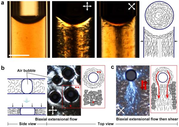
At concentrations above about 10 mg/ml, these nematic phases cease to flow when flipped vertically in a test-tube, indicating formation of a highly viscous phase or physical gel, in which the GO plates form the percolating gel framework. The assembly of liquid crystal phases and the structure of materials made through LC intermediates (mesogenic materials) depends not only on bulk phase behavior, but also by flow alignment and surface anchoring states.19,20,22 The surface anchoring states of GO are unknown, but can be revealed through structures in confined microspaces and near interfaces.20,22 Figure 2a shows GO suspensions above the isotropic-nematic (I-N) transition infiltrated into glass micro-capillary tubes. Under 0°/90° crossed polars, the liquid is dark except for the sloped regions at the liquid-air interface. Rotation of the cross-polars by 45° reverses the light-dark pattern (middle panel) and indicates the layer orientational pattern sketched at the far right. GO layers anchor homeotropically (face-on) at the liquid-glass and liquid-air interfaces. Additional evidence for this behavior is seen at the surfaces of air bubbles trapped between two glass slides confining GO suspensions (Fig. 2b,c) and by the birefringence near the surface of an immersed metal wire (Supplementary Fig. 4). The homeotropic anchoring of GO sheets is not unexpected. Anchoring states in lyotropic liquid crystals are typically dominated by entropic effects, and there is a free energy reduction associated with homeotropic anchoring, since is minimizes excluded volume at the interface according to:23
| (2) |
where G is the orientational contribution to the interfacial free energy per unit area, n is the number density of the GO sheets, d is their lateral dimension, and θ is the angle between the GO planes and the substrate. There is an additional driving force specific to GO that relates to interfacial adsorption. The charged periphery and uncharged face of GO sheets impart an amphiphilic character that causes adsorption at the gas-water interface.11,12 In the case of GO, the hydrophobic graphitic domains are located at the plate faces, and the energy-driven homeotropic (face-on) adsorption essentially templates the same alignment in the fluid region immediately adjacent to the interface. Both factors (excluded volume entropy and adsorption energy) combine to give a strong preference for homeotropic alignment of GO, as seen at each of the interfaces studied in our studies (air, glass, silanized glass, steel). As dilute GO suspensions dry, the receding liquid front collects GO layers in an anchored surface deposit if diffusion away from the drying front is slow. Behind the surface deposit is a film of enriched GO in the nematic state, whose thickness is estimated to be of order 100 μm (Supplementary Fig. 2).
Figure 2. Assembly modes in graphene oxide aqueous phases: surface anchoring, microconfinement, and flow ordering.
a, Infiltration of 10 mg/ml GO suspension into 1 mm diameter cylindrical capillaries leads to a well-defined concentric layer patterns driven by homeotropic surface anchoring at the glass walls and shear flow into the capillary. b, Biaxial extensional flow (squeezing flow) orients GO platelets perpendicular to the compression direction leading to large non-birefringent (black) regions under crossed polars in top view (see *). The presence of air bubbles in the GO suspension also leads to vertically aligned GO layers in the near-surface region of the bubbles reflecting homeotropic surface anchoring. This alignment is clearly seen by the bright lenses at 45°/135°/225°/315° under 0°/90° crossed polars (see **). Rotation of crossed polars causes equivalent rotation in these features clearing indicating the surface anchored pattern shown in the top view sketch at the far right. c, Following biaxial extension flow by oscillating shear flow leads to vertically aligned “wakes” of GO layers forced to flow around the lens-shaped air bubbles (top view). The vertically aligned GO layers are trapped in the viscous LC phase are stable after oscillating shear flow is stopped (scale bar: 400 μm).
An important assembly mechanism for liquid crystals is flow ordering (Fig. 2b,c). Pressing a small amount of GO suspension between two glass slides creates biaxial extensional flow, or squeezing flow, which orients discotic mesogens parallel to the two confining surfaces (Fig. 2b). Again, homeotropic surface anchoring is seen at edges of trapped air bubbles (Fig. 2b), and this surface anchoring templates the vertical alignment of GO layers, which in oscillating shear flow (Fig. 2c) produces optically active “wakes” behind the bubbles. Overall, flow and surface anchoring are dominant factors determining layer orientation in GO liquid crystals.
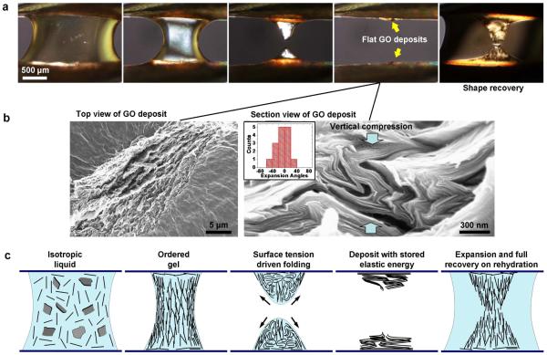
During our study of GO assembly we observed a surprising drying and rehydration behavior (Figs. 3-5). Figure 3 shows an hourglass droplet (2 mg/ml aqueous GO) undergoing drying between two metal needles. Evaporation causes gradual thinning of the drop until instability in the stretched liquid bridge causes breakage, and surface tension drives collapse of the droplet into thin deposits on the two opposing substrates. Upon re-addition of water, the deposits swell, rise vertically, and return to the same volume and shape as the original droplet before breakage (Fig. 3). This gel-like phase is stable for some minutes, and then slowly redisperses into a GO suspension. This phenomenon occurs if rehydration is carried out soon after drying, or if the deposit is vacuum dried overnight, but not if the deposit is converted from GO to reduced GO by annealing at 450 °C in N2 flow for 15 min. The effect is much less pronounced if the deposits are wetted with ethanol or acetone. The phenomenon is fully repeatable in this geometry, and similar behavior can be seen for droplets suspended in millimeter slits or fine wire rings.
Figure 3. Hydration-responsive folding and unfolding transitions.
Optical micrographs of hourglass-shaped droplet of 2 mg/ml GO suspension positioned in millimeter gap between two metal needles. Left-to-right: drying causes surface recession, concentration of the GO layers and eventually physical gelation due to interlayer interaction. Instability in late stages of drying causes rupture of the hourglass droplet and Z-directional collapse driven by surface tension. Rehydration triggers anisotropic growth and recovery of original shape. The final state does not immediately redissolve, but is stable for some period in a gel-like state. b, SEM images of dried deposit: Left: top view showing upward facing GO edge surfaces on top plane, Right: cross-sectional SEM showing extreme accordion folded morphology that reflects vertical compression of the low-mobility plate network in the concentrated suspension. Inset gives statistical data extracted from image on the fold orientation (preferred expansion/contraction vector), which indicates formation by Z-directional compression (see Supplemental). c, Proposed molecular assembly of GO plates during drying and rehydration. Receding drying front templates vertical alignment of GO layers by surface anchoring; increase in concentration causes layer-to-layer interaction and partial gelation; thinning causes liquid bridge instability, surface tension drives vertical collapse and folding, and rehydration triggers unfolding, expansion, and shape/size recovery.
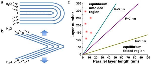
Figure 5. Mechanics of water-actuated unfolding.
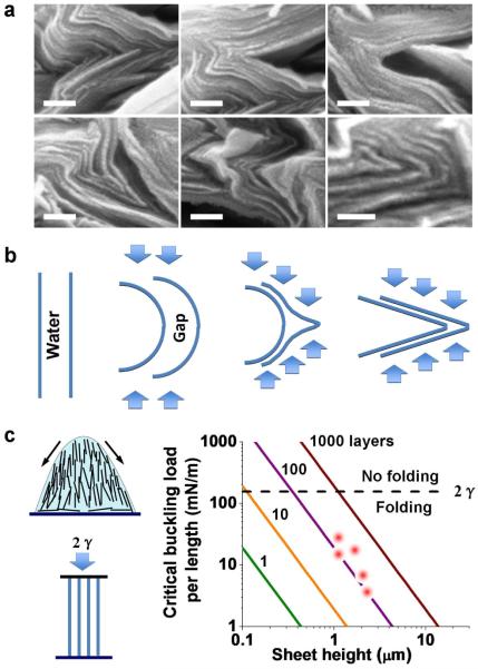
a, Nested half-cylindrical loops that are the idealized folded structures from the buckling of close-packed layers with no slippage. b, Nested triangular structures that closely resemble the experimental folds in dried GO deposit. c, Calculated phase diagram showing minimum energy state (folded vs. unfolded) as a function of tip curvature (assuming triangular folds) and length of parallel layer segment along cleavage planes (as shown in a). Points described experimental features in Fig. 3. Most of the experimental folded structures are triangular and have short or no cleavage planes. This analysis shows that the experimental folds are non-equilibrium structures held in place by interlayer friction, which is released by water intercalation on rehydration.
Figure 3b shows the characterization of the dried deposits. They have upward facing GO edges at the top surface, and show extreme accordion-like folding in cross section. The fold orientations carry the signature of the vertical compression that follows breakage of the stretched liquid bridge (Fig. 3b histogram, Supp. Fig. 5). Figure 3c gives our conceptual model of the drying and rehydration process. In this geometry, liquid crystal surface anchoring aligns GO layers vertically due to the vertical air-liquid interface. This layer alignment also templates liquid crystal order behind the surface film, and further drying gives a vertically oriented GO gel-like phase, where layer-to-layer interactions severely restrict individual layer rotational motion. Surface tension during the late stages of drying acts primarily in the vertical direction (third panel), and the interacting layers in the gel network are bent into accordion-folded multi-layer structures that store elastic energy. Folding of single GO layers by liquid surface tension has been explored theoretically by Patra et al.24 for the case of nanodroplets on patterned graphene sheets of varying shape. Key to the accordion fold structure seen here is creation of a vertically aligned nematically ordered GO phase at high concentration, and the arrangement of balanced surface tension forces parallel to that vertical alignment.
We hypothesized that the observed behavior is a folding/unfolding transition, in which rehydration lowers interlayer forces and releases the elastic fold energy stored previously by liquid surface tension during drying (Fig. 3 sketch). This hypothesis is supported by our modeling work on the nanomechanics of folding (Fig. 4) and unfolding (Fig. 5). The folding process is a buckling instability, and because it occurs in a concentrated gel-like phase, the load-bearing elements are GO sheets that form a connected framework. If individual GO layers were free to rotate, they would align parallel to the substrate in response to the squeezing flow introduced by surface tension, as seen directly in the squeezing flow experiments in Fig. 2. In this concentrated suspension, however, interlayer connectivity prevents single-layer rotation and the same driving force gives rise to buckling instead. Even at this late stage of drying, the majority component of the concentrated GO phase is water, which allows slippage of parallel GO layers, and thus the appropriate model is one based on the buckling of independent parallel vertical sheets (Fig. 4c). This model is supported by the morphology of the folded structures, which are not nested half-cylindrical loops (Fig. 5a) as one would expect from the bending of close-packed layers, but rather triangular folds or “nose-shaped” structures with inflection points (Fig. 4b) that occur because of the water-filled spaces between sheets in the gel-like phase. Applying the Euler buckling theory to a set of n independent vertically aligned GO layers (Young’s modulus, E ~ 200 GPa)25 gives the buckling criterion:
| (3) |
where h is the layer height, and l the layer thickness taken as 1 nm. Figure 4c shows that water surface tension is easily sufficient to buckle these vertically aligned nematic GO layers.
Figure 4. Mechanics of water-actuated folding.
a, Examples of triangular and “nose-shaped” folds in cross-sectional SEM images of the dried GO deposit (scale bar: 100 nm). b, Sketch showing the formation mechanism of triangular or nose-shaped fold structures, which are favored due to the abundance of water between GO sheets in the original suspension. c, Eulerian buckling model applied to multiple independent vertically aligned GO sheets as structural beams. Left: sketch and model formulation, Right: Calculation of critical buckling load (maximum force) as a function of the number of sheets in a packet and their height. Points represent layer packets observed in panel a. All layer packets are predicted to be unstable in the presence of water surface tension, and to buckle and fold, in agreement with observation.
Our most interesting observation is hydration actuated unfolding, which for GO to our knowledge has never before been observed experimentally or proposed theoretically. It is clear that rehydration releases stored elastic energy in folded GO, but the release mechanism was initially unclear. We first hypothesized that the folded structures are stabilized in the dry state by interlayer forces along potential cleavage planes (Fig. 5a), which for GO have been proposed to be primarily due to interlayer hydrogen bond networks.26 The total energy of this system, E, is the sum of elastic fold energies and interlayer energies integrated over regions that must cleave for unfolding to occur:
| (4) |
where εe is the bending energy constant of GO, R the radius of curvature for layers k = 1 through n in the nested half-cylinder structures, εi the interlayer energy constant, and L the length along the cleavage plane (Fig. 5a). Most of the observed folds, however, are more triangular (Figs. 4a, 5b) than half-cylindrical, and have radii of curvature at the tip less than 10 nm. The total energy for the case of nested triangle structures is:
| (5) |
where n is the number of layers in the nested triangular fold. Figure 5c is a folding phase diagram based on Eq. 5, and includes data points from the SEM images. All of data lie in the region where the unfolded structures are energetically favored, meaning the dry (folded) deposits are non-equilibrium features. The points lie in the far left region of the plot because the cleavage planes depicted in Fig. 5a are short in length or absent altogether. Most of the observed structures are not fully folded, but open at the back, as depicted in Fig. 5b. In these cases there is no energy penalty for unfolding, and the folded triangles are clearly nonequilibrium structures. These structures are held in place by frictional forces, since the complex collective unfolding process will certainly require some interlayer slip.
Interlayer frictional forces can be estimated as f=μσi A, where f is the static frictional force, μ the coefficient of friction, σi the GO interlayer attractive force, and A the total interlayer contact area. The area, A is (n-1)hL, where n is the number of GO layers in the system, and h and L the dimensions of the system. For μ=0.1, σi=230 MPa,27 h=L=400 μm, and a GO concentration of 10 mg/ml, the static frictional forces are estimated at >103 Newtons, which far exceeds the water surface tension force, 2γL (~ 6×10⁻⁵ N) that produced the initial elastic deformation. It is clear that frictional forces in the dry state are sufficient to kinetically stabilize the non-equilibrium folded structures.
Upon rehydration, water intercalation increases interlayer spacing and greatly reduces interlayer frictional forces, as has been reported in calculations of the shear modulus for graphene oxide papers.26 The reduction of shear modulus allows rapid relaxation to the unfolded state, which is the minimum energy state by the analysis in Fig. 5. Note that we can observe a crude but related behavior in GO multilayer deposits formed from droplet drying, which wrinkle under compressive stresses during deposition, and partially unwrinkled if rehydrated (Supplementary Fig. 3).
Overall, we show that graphene oxide can be systematically assembled through surface anchoring, flow, and microconfinement into complex multilayer structures that can form the basis for advanced GO or carbon-based materials. The ability to fold and unfold sets GO apart from other molecular building blocks, and is the basis for the new hydration-actuated folding and rehydration actuated unfolding behavior observed here. More work is needed on other solvents, salt effects, and the influence of drying speed. This opens the potential to fabricate a whole new class of GO-based smart, stimuli-response materials. Hydration-responsive folding/unfolding of GO may find application in controlled release, in nano/micro-electro-mechanical devices, or in dynamic space filling or sealing applications.
METHODS
Graphene oxide was prepared by a modified Hummers and Offeman’s method28,29 and stored in stock suspensions of 1 mg/ml. The detailed synthesis and purification procedures are described in Kim et al.29 This procedure has been shown previously to yield a majority of monolayers as confirmed here by atomic force microscopy. The lateral sizes are particularly important for liquid crystal formation, so the size distribution was characterized by SEM on GO sheets casted on a Si substrate (Supplementary Fig. 1). The areas of GO flakes in the SEM images were measured using digital image analysis (ImageJ, version 1.4), which recognizes the plane area of GO by the contrast relative to the substrate, and automatically calculates the area of each sheet. An effective lateral dimension of each sheet was calculated as the diameter of a circle having the equivalent area.
The GO liquid crystal phases were examined on an Olympus BX60 System Microscope and the dried deposits on a LEO 1530 SEM (at 5 kV below 10−5 Torr) after coating with gold–palladium by a PS-2 sputter-coating unit (International Scientific Instruments) for 30 s (1.2 kV, 20 mA, vacuum argon environment). Microcapillary infiltration experiments were carried out using calibrated micropipets (10 μL, VWR Scientific). Selected glass slides were treated in a 10 % dimethyldichlorosilane solution in toluene overnight to make the surfaces hydrophobic.
The modeling of hydration-reponsive folding and unfolding requires estimation of mechanical properties for graphene oxide from the literature, and the values were Young’s modulus (E ~ 200 GPa);25 bending energy constant (εe ~ 2.22 eV);30 and interlayer attractive force (σi ~ 230 MPa).27 Note that in GO the interlayer energy is proposed to be due primarily to hydrogen bonding, which includes direct layer-to-layer H-bonds and those involving bridging water molecules.26 For GO we used an interlayer energy of ~ 3 eV/nm2, which is slightly higher than in pristine graphene, whose interlayer attraction (2.48 eV/nm2)30 involves only vdW forces.
Supplementary Material
Acknowledgements
Financial support was provided by National Science Foundation, through the Brown University MRSEC (DMR0520651), the China Scholarship Council (CSC), and the Superfund Research Program Grant P42ES013660 from the National Institute of Environmental Health Sciences.
Footnotes
Supporting Information Available: Characterization of GO, surface deposition and nematic liquid crystal film formation, additional information on folding and unfolding transitions, geometric analysis of folding patterns in GO deposits. This material is available free of charge via the Internet at http://pubs.acs.org.
REFERENCES
- 1.Ruoff RS. Calling All Chemists. Nat. Nanotechnol. 2008;3:10–11. doi: 10.1038/nnano.2007.432. [DOI] [PubMed] [Google Scholar]
- 2.Eda G, Fanchini G, Chhowalla M. Large-Area Ultrathin Films of Reduced Graphene Oxide as A Transparent and Flexible Electronic Material. Nat. Nanotechnol. 2008;3:270–274. doi: 10.1038/nnano.2008.83. [DOI] [PubMed] [Google Scholar]
- 3.Wang X, Zhi LJ, Mullen K. Transparent, Conductive Graphene Electrodes for Dye-Sensitized Solar Cells. Nano Lett. 2008;8:323–327. doi: 10.1021/nl072838r. [DOI] [PubMed] [Google Scholar]
- 4.Bagri A, Mattevi C, Acik M, Chabal YJ, Chhowalla M, Shenoy VB. Structural Evolution During the Reduction of Chemically Derived Graphene Oxide. Nat. Chem. 2010;2:581–587. doi: 10.1038/nchem.686. [DOI] [PubMed] [Google Scholar]
- 5.Compton OC, Nguyen ST. Graphene Oxide, Highly Reduced Graphene Oxide, and Graphene: Versatile Building Blocks for Carbon-Based Materials. Small. 2010;6:711–723. doi: 10.1002/smll.200901934. [DOI] [PubMed] [Google Scholar]
- 6.Compton OC, Dikin DA, Putz KW, Brinson LC, Nguyen ST. Electrically Conductive “Alkylated” Graphene Paper via Chemical Reduction of Amine-Functionalized Graphene Oxide Paper. Adv. Mater. 2010;22:892–896. doi: 10.1002/adma.200902069. [DOI] [PubMed] [Google Scholar]
- 7.Pei SF, Zhao JP, Du JH, Ren WC, Cheng HM. Direct Reduction of Graphene Oxide Films into Highly Conductive and Flexible Graphene Films by Hydrohalic Acids. Carbon. 2010;48:4466–4474. [Google Scholar]
- 8.Stankovich S, Dikin DA, Dommett GHB, Kohlhaas KM, Zimney EJ, Stach EA, Piner RD, Nguyen ST, Ruoff RS. Graphene-Based Composite Materials. Nature. 2006;442:282–286. doi: 10.1038/nature04969. [DOI] [PubMed] [Google Scholar]
- 9.Wang L, Lee K, Sun YY, Lucking M, Chen ZF, Zhao JJ, Zhang SBB. Graphene Oxide as an Ideal Substrate for Hydrogen Storage. ACS Nano. 2009;3:2995–3000. doi: 10.1021/nn900667s. [DOI] [PubMed] [Google Scholar]
- 10.Jiang X, Ma YW, Li JJ, Fan QL, Huang W. Self-Assembly of Reduced Graphene Oxide into Three-Dimensional Architecture by Divalent Ion Linkage. J. Phys. Chem. C. 2010;114:22462–22465. [Google Scholar]
- 11.Kim J, Cote LJ, Kim F, Yuan W, Shull KR, Huang JX. Graphene Oxide Sheets at Interfaces. J. Am. Chem. Soc. 2010;132:8180–8186. doi: 10.1021/ja102777p. [DOI] [PubMed] [Google Scholar]
- 12.Cote LJ, Kim J, Tung VC, Luo JY, Kim F, Huang JX. Graphene Oxide As Surfactant Sheets. Pure. Appl. Chem. 2011;83:95–110. [Google Scholar]
- 13.Dikin DA, Stankovich S, Zimney EJ, Piner RD, Dommett GHB, Evmenenko G, Nguyen ST, Ruoff RS. Preparation and Characterization of Graphene Oxide Paper. Nature. 2007;448:457–460. doi: 10.1038/nature06016. [DOI] [PubMed] [Google Scholar]
- 14.Zhu YW, Murali S, Cai WW, Li XS, Suk JW, Potts JR, Ruoff RS. Graphene and Graphene Oxide: Synthesis, Properties, and Applications. Adv. Mater. 2010;22:5226–5226. doi: 10.1002/adma.201001068. [DOI] [PubMed] [Google Scholar]
- 15.Kim JE, Han TH, Lee SH, Kim JY, Ahn CW, Yun JM, Kim SO. Graphene Oxide Liquid Crystals. Angew. Chem., Int. Ed. 2011;50:3043–3047. doi: 10.1002/anie.201004692. [DOI] [PubMed] [Google Scholar]
- 16.Xu Z, Gao C. Aqueous Liquid Crystals of Graphene Oxide. ACS Nano. 2011;5:2908–2915. doi: 10.1021/nn200069w. [DOI] [PubMed] [Google Scholar]
- 17.Behabtu N, Lomeda JR, Green MJ, Higginbotham AL, Sinitskii A, Kosynkin DV, Tsentalovich D, Parra-Vasquez ANG, Schmidt J, Kesselman E, et al. Spontaneous High-Concentration Dispersions and Liquid Crystals of Graphene. Nat. Nanotechnol. 2010;5:406–411. doi: 10.1038/nnano.2010.86. [DOI] [PubMed] [Google Scholar]
- 18.Guo F, Mukhopadhyay A, Sheldon BW, Hurt RH. Vertically Aligned Graphene Layer Arrays from Chromonic Liquid Crystal Precursors. Adv. Mater. 2011;23:508–513. doi: 10.1002/adma.201003158. [DOI] [PubMed] [Google Scholar]
- 19.Hurt RH, Chen ZY. Liquid Crystals and Carbon Materials. Phys. Today. 2000;53:39–44. [Google Scholar]
- 20.Chan C, Crawford G, Gao YM, Hurt R, Jian KQ, Li H, Sheldon B, Sousa M, Yang N. Liquid Crystal Engineering of Carbon Nanofibers and Nanotubes. Carbon. 2005;43:2431–2440. [Google Scholar]
- 21.Forsyth PA, Marcelja S, Mitchell DJ, Ninham BW. Onsager Transition in Hard Plate Fluid. J. Chem. Soc., Faraday Trans. 2. 1977;73:84–88. [Google Scholar]
- 22.Gennes PG, Prost J. The Physics of Liquid Crystals. 2nd ed Clarendon Press; Oxford University Press; Oxford New York: 1995. [Google Scholar]
- 23.Bahadur B. Liquid Crystals: Applications and Uses. World Scientific; Singapore ; Teaneck, NJ: 1990. pp. 14–20. [Google Scholar]
- 24.Patra N, Wang BY, Kral P. Nanodroplet Activated and Guided Folding of Graphene Nanostructures. Nano Lett. 2009;9:3766–3771. doi: 10.1021/nl9019616. [DOI] [PubMed] [Google Scholar]
- 25.Suk JW, Piner RD, An J, Ruoff RS. Mechanical Properties of Monolayer Graphene Oxide. ACS Nano. 2010;4:6557–6564. doi: 10.1021/nn101781v. [DOI] [PubMed] [Google Scholar]
- 26.Medhekar NV, Ramasubramaniam A, Ruoff RS, Shenoy VB. Hydrogen Bond Networks in Graphene Oxide Composite Paper: Structure and Mechanical Properties. ACS Nano. 2010;4:2300–2306. doi: 10.1021/nn901934u. [DOI] [PubMed] [Google Scholar]
- 27.Aitken ZH, Huang R. Effects of Mismatch Strain and Substrate Surface Corrugation on Morphology of Supported Monolayer Graphene. J. Appl. Phys. 2010;107:123531. [Google Scholar]
- 28.Hummers WS, Offeman RE. Preparation of Graphitic Oxide. J. Am. Chem. Soc. 1958;80:1339–1339. [Google Scholar]
- 29.Kim F, Luo JY, Cruz-Silva R, Cote LJ, Sohn K, Huang JX. Self-Propagating Domino-like Reactions in Oxidized Graphite. Adv. Funct. Mater. 2010;20:2867–2873. [Google Scholar]
- 30.Tomanek D. Mesoscopic Origami with Graphite: Scrolls, Nanotubes, Peapods. Physica. B. 2002;323:86–89. [Google Scholar]
Associated Data
This section collects any data citations, data availability statements, or supplementary materials included in this article.


