

Abstract
The introduction of the Balzers freeze-fracture machine by Moor in 1961 had a much greater impact on the advancement of electron microscopy than he could have imagined. Devised originally to circumvent the dangers of classical thin-section techniques, as well as to provide unique en face views of cell membranes, freeze-fracturing proved to be crucial for developing modern concepts of how biological membranes are organized and proved that membranes are bilayers of lipids within which proteins float and self-assemble. Later, when freeze-fracturing was combined with methods for freezing cells that avoided the fixation and cryoprotection steps that Moor still had to use to prepare the samples for his original invention, it became a means for capturing membrane dynamics on the millisecond time-scale, thus allowing a deeper understanding of the functions of biological membranes in living cells as well as their static ultrastructure. Finally, the realization that unfixed, non-cryoprotected samples could be deeply vacuum-etched or even freeze-dried after freeze-fracturing opened up a whole new way to image all the other molecular components of cells besides their membranes and also provided a powerful means to image the interactions of all the cytoplasmic components with the various membranes of the cell. The purpose of this review is to outline the history of these technical developments, to describe how they are being used in electron microscopy today and to suggest how they can be improved in order to further their utility for biological electron microscopy in the future.
Keywords: quick-freeze, deep-etch, platinum replication, electron microscopy
Introduction
The introduction of the Balzers freeze-fracture machine by Hans Moor in 1961 [1] had a much greater impact on the advancement of electron microscopy than he could have ever imagined. Devised originally to circumvent the dangers of dehydration and plastic embedding required for classical thin-section techniques, as well as to provide unique en face views of cell membranes that could not be obtained by classical thin-section techniques, freeze-fracturing proved to be crucial for developing modern concepts of how biological membranes are organized, as it proved once and for all that membranes are bilayers of lipids within which proteins float and self-assemble in the myriads of ways that lead to the proper functioning of the cell. Later, when freeze-fracturing was combined with methods for freezing cells that allowed microscopists to avoid even the aldehyde-prefixation and cryoprotection steps that Moor had still to use to prepare the samples for his original invention [2,3], it became a means for capturing membrane dynamics on the millisecond time-scale, thus allowing a deeper understanding of the functions of biological membranes in living cells as well as their static ultrastructure.
Finally, the realization that non-fixed, non-cryoprotected samples could be deeply vacuum-etched or even freeze-dried after freeze-fracture [4] opened up a whole new way to image all the other molecular components of cells besides their membranes and also provided a powerful means to image the interactions of all the cytoplasmic components with the various membranes of the cell. Thus, the molecular ‘coats’ and ‘scaffolds’ that form on the surfaces of membranes, both inside and outside, could be imaged at sufficient resolution to reveal their mechanism of action upon membranes in all sorts of cellular processes as diverse as exocytosis, endocytosis, vesicular transport, viral morphogenesis and budding, etc. [5–7]. The purpose of this review is to briefly outline the history of all these technical developments in freeze-etching and to describe how they are being used in electron microscopy even today and to suggest how they can be improved in the future in order to further their utility for biological electron microscopy.
Description and critique of platinum replication
First, we briefly review the method of platinum replication that has always been used throughout the history of freeze-fracturing, from Hans Moor's original freeze-fracturing [1,8–10] to all the present-day ‘quick-freeze, deep-etch’ methods reviewed in this article. The ‘secret to the success’ of all these approaches has always been the simple fact that frozen biological samples somehow tolerate the generation of platinum replicas on their surfaces, despite it being done using the amazingly harsh and hot procedure of vacuum evaporation of molten platinum (from a source or a ‘gun’ operating at >3800°C). How or why this works (i.e. why frozen cells can tolerate this) is still a total mystery and a bit of a miracle. Why frozen cells do not melt under the withering heat and light of the vacuum evaporator, especially when gaseous platinum condenses on their surfaces to form a solid metallic replica of their most delicate contours, is still not understood – but that it does work cannot be doubted. No one has ever documented any melting phenomena in freeze-etch replicas, even though a whole host of other artifacts can occur during improper platinum replication. Thanks to this miracle of platinum replication, freeze-etched samples can be viewed at a much higher resolution than is obtainable with scanning electron microscopy [even with the new scanning electron microscopes (SEMs) with advanced field-emission electron sources], because a thin platinum replica can be viewed using the transmission EM. Indeed, when we introduced the ‘deep-etch’ technique three decades ago, in the days long before field-emission SEM, we described it as an alternative to high-resolution SEM [4], and even today, some of our closest collaborators mistakenly describe our ‘deep-etch’ procedure as actually being high-resolution SEM, which it is not.
Platinum replicas have been recognized to be ideal samples for TEM since the earliest days of biological EM [11–14]. This is due to the exceedingly high contrast that they offer and their near imperviousness to electron-beam damage. Moreover, they are relatively fine-grained, thus are faithful to the contours of the original sample onto which they are applied, offering significant and meaningful topological information down to ∼3 nm resolution. Efforts to reduce the granularity of freeze-fracture replicas in order to further improve this resolution, by further lowering the temperature of the frozen sample or by amalgamating other metals into platinum, or by switching entirely to higher melting-point metals such as tantalum and tungsten, have offered modest improvements [15–17], but they have not generally been necessary or advisable. Thus, the ‘shadowing’ techniques that were originally developed by Robley Williams and William Wyckoff in the early 1940s (op. cit.) and that were used so effectively to demonstrate the first hints of molecular architecture in the TEM in the days before thin-sectioning was even perfected [18–20] were adopted essentially unchanged by Moor and his colleagues in their initial establishment of freeze-etching [1] and are being used even today in the latest versions of ‘deep-etching’ as well as other powerful forms of freeze-fracturing such as Kazushi Fujimoto's replica immunolabeling procedure [21,22] (as detailed by Toyoshi Fujimoto in this 60th Anniversary Issue). Indeed, the images provided in this review are all such simple, primitive platinum replicas, albeit presented in anaglyph 3D to illustrate their remarkable preservation of topological information. Debate has erupted over the years about the best way to prepare platinum replicas, and their 3 nm resolution limit has often been decried [23,174]; but still today, platinum replicas represent the only way to view membrane surfaces at sufficient resolution to see their associated protein molecules, and to do so by direct inspection in the TEM, rather than by the laborious image-reconstruction techniques described elsewhere in this anniversary issue.
Finally, no discussion of the history or contemporary use of platinum replication can omit the huge ‘boost’ that this technique got when Branton introduced the rotary-replication procedure in 1976 [23–25]. Before that, all replicas had been unidirectional ‘shadow castings’ produced by applying platinum from a fixed-angle platinum source onto a stationary sample. Although beautiful (and informative, since the shadows provided accurate z-axis information regarding the exact height of the sample above the substrate), they were not terribly easy to interpret, particularly for samples that possessed a complex 3D topology. Thus, they contributed little to the understanding of whole-cell ultrastructure per se and were applied mostly to isolated cellular components, macromolecules, viruses and bacteria. Luckily, right at the time that we began to realize that non-cryoprotected ‘quick-frozen’ samples could be ‘deep-etched’ or freeze-dried, due simply to the lack of a cryoprotectant [4], Branton's rotary-replication technique came along to solve our problem of losing details in the depths from overly dark shadows and excessively high relief. All we needed was a method to rotate our samples while platinum was being deposited and while they were being kept frozen. Again, the Balzers company came to our rescue and it designed and marketed a rotary-cryostage that could be retro-fitted into the existing freeze-etch machines, and we were ‘off and running’. While not depositing platinum from all angles, as is done with the omni-directional metal coating used in SEM (or as accomplished with ‘sputter-coating’ – a technique not readily adaptable to platinum or to frozen samples), nevertheless, Branton's fixed-angle rotary replication created the impression of uniform metal coating and thereby yielded images that looked delightfully like those produced by ultra-high-resolution SEM. This was the ‘final piece of the puzzle’ that made our deep-etch technique a robust and widely applicable approach to electron microscopy.
A brief history of ‘freeze-etch’ EM
Although Hans Moor was heralded as the founder of the technique, he was, of course, not working in a vacuum (no pun intended) but had predecessors who led the way – most notably a student of Robley Williams named Russell Steere, who worked most of his career in an obscure post at the Beltsville Agricultural Station of the US Government, but who was truly the originator of the whole field [26] and who actually taught us the freeze-fracture technique, personally, in the early 1970s. Steere actually built the first primitive freeze-fracture device in the mid-1950s, far in advance of Moor and his colleagues [27]. Later, Steere developed a ‘double-replica’ device that allowed him to split a frozen sample into two and replicate both halves [28]. Thereby, he produced complimentary views of fractured membranes from opposed vantage points, which was an extremely important demonstration that freeze-fracturing did not seriously distort biological membranes – except in certain interesting details that can be gleaned by reviewing Steere's early papers [26–29]. Also active in the field at about this time was the New Zealander Stanley Bullivant, who developed an ingeniously simple device for performing freeze-fracturing [30] and used it effectively in a series of studies with Ron Weinstein at the Massachusetts General Hospital to learn more about membrane structure [31]. What all these pioneers failed to do, and where Hans Moor succeeded, was to establish an excellent working relationship with a commercial manufacturer of vacuum evaporators (Balzers, Inc., in Lichtenstein) and work together with the company to produce a quality-machined cryomicrotome that would mount inside their evaporators. This provided electron microscopists around the world with a really straightforward means to perform freeze-fracturing and the field took off.
It is important to note here that Dan Branton, mentioned above for his invention of rotary replication, traveled to Switzerland as a young man to do a post-doc with Hans Moor, and in this context, was the first to recognize that freeze-fracturing did not actually expose membrane surfaces, as his Swiss mentors believed at the time, but that it actually split membranes through their interiors, separating the two opposed leaflets of the phospholipid bilayer and yielding internal ‘faces’ of the bilayer [32,33]. Branton ultimately named these ‘P’ and ‘E’ faces (‘P’ for the half that rests on the cytoplasm or protoplasm and faces out from the cell and ‘E’ for the half that has extracellular (or in the case of organelles, luminal) space behind it and faces toward the cytoplasm (e.g. the outer leaflet of the plasmalemma) [34]. Branton's finding of complimentary bumps or protrusions on one face, matching complimentary pits on the opposite face, led further to the notion that these ‘intramembrane particles’ (‘IMPs’) were likely to be transmembrane proteins and the seemingly random distribution of these IMPs in most freeze-fracture replicas (with notable exceptions at cell junctions, etc.) led in large measure to Singer and Nicholson's famous ‘fluid-mosaic’ model of the cell membrane [35,36]. Perhaps this is why, even today, freeze-fracturing of unfixed membranes offers the most direct means for determining the extent to which certain membrane proteins are in some cases non-randomly distributed into domains such as ‘rafts’ within the membrane.
In any case, the fundamental point of this brief historical review of freeze-fracturing is to stress that the technique is still capable of teaching us many important things about membranes, thanks to the fact that the pioneers mentioned above developed robust and reproducible ways to carry out the procedure, and in doing so, they proved that freeze-fracturing does not reveal membrane surfaces per se, but rather membrane ‘faces’ – internal views of the bilayer that are beautifully punctuated by ‘particles’ that represent transmembrane proteins – all the channels, pumps, receptors and effectors that we now know function within the living cell membrane. The later development of ‘deep-etching’ was required to allow microscopists to finally replicate and image the true surfaces of biological membranes.
The introduction of ‘deep-etching’
The term ‘freeze-etching’ was often used by Moor and others in the early days of freeze-fracturing [1,8–10], but this so-called etching was usually brief (around 1 min) and was always carried out on tissues impregnated with high concentrations of antifreezes (generally 20–30% glycerol), which have a very low vapor pressure, hence a very low tendency to vacuum sublime at the −100 to −150°C temperatures used in most freeze-fracture machines. Consequently, very little ‘etching’ actually was done in those days – only enough to slightly roughen up non-membranous regions and thus highlight the relative smoothness of membrane fracture faces. Only after the need for antifreezes was overcome, by developing ultra-rapid methods of freezing that did not allow sufficient time for ice crystals to form, was it possible to subject a freeze-fractured sample to a significant period of vacuum sublimation and thereby to remove enough ice to finally observe membrane surfaces to a greater extent [2,3] (see also [37,38]). The greater vapor pressure of ice compared with that of glycerol (5× log10 greater) meant that if we left a fractured sample in vacuum at −100°C for a minute or two before we generated the platinum replica of its surface, we could achieve a substantial degree of etching – roughly a quarter micron or more. (We came upon this quite by accident, during a teaching session at the Marine Biology Laboratory in Woods Hole. While explaining the freeze-fracture procedure to a group of students, our timing got off and we delayed the platinum-evaporation step to almost 5 min after performing freeze-fracturing. The students exclaimed at the time that this first ‘deep-etched’ sample looked like something straight out of Walt Disney Studios – almost a cartoon of the usual freeze-fracture replica.)
Subsequently, we realized that because we had no cryoprotectants in our samples, we could prolong the ‘etch’ period at −100°C up to 15 min or so and thereby achieve complete freeze-drying of our samples (i.e. achieve vacuum sublimation up to >10 μm in depth) [4]. This is enough to expose an entire monolayer of tissue-cultured cells and, in fact, it paved the way to our imaging using the TEM anything that could be applied as a monolayer onto any solid substrate, from cells (Figs. 2–4), to bacteria and viruses, to macromolecules (Fig. 5) or bacteria to viruses, to macromolecules, or to man-made materials such as liposomes, or more recently, at the new iCeMS Institute in Kyoto, to ‘mesoscale’ entities such as drug-delivery particles (10–100 nm), or even to nanoscale entities such as carbon fibers and fullerenes. Such freeze-drying of samples adsorbed to solid substrates thus complimented and extended our earlier efforts to view all such materials by freeze-fracturing aqueous suspensions of them. It truly brought the original Balzers freeze-etch machines to the point where they were creating samples not unlike the original replicas viewed by Williams and Wyckoff in the 1940s – but with the huge advantage that the samples' 3D topology could finally be properly preserved by freeze-drying, where this topology was largely obliterated during the air-drying step that could not be avoided in the early days. The 3D ‘anaglyph’ images presented in this article review these developments and applications.
Fig. 2.
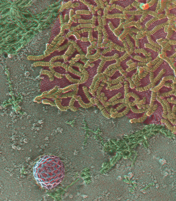
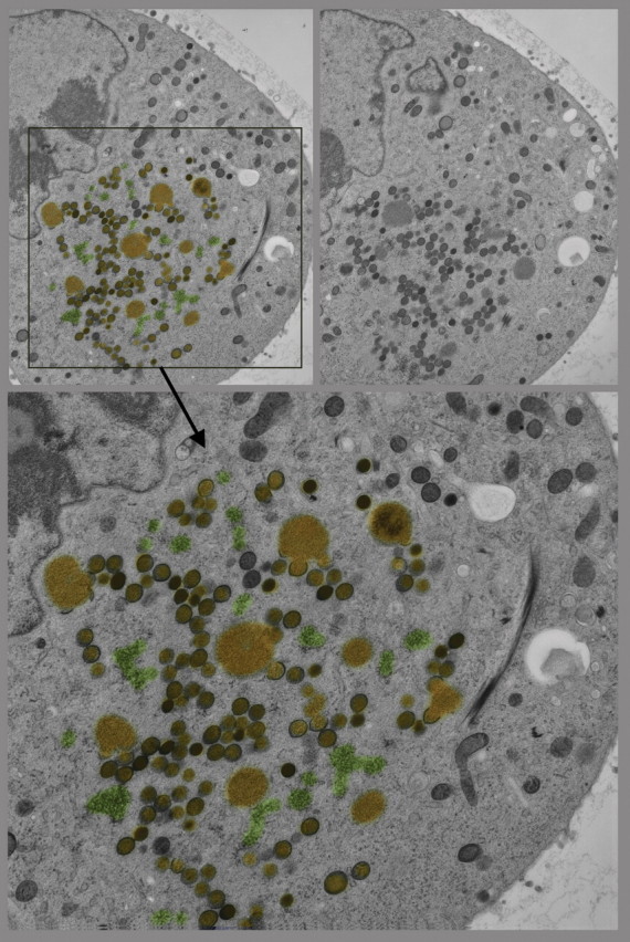
Quick-freeze, deep-etch, rotary replication (QF-DE-RR) view of the inside surface of a cell infected with the SSPE version of measles virus, circa 1984 (unpublished), illustrating the helical viral nucleocapsid (yellow) strongly and specifically attached to an orthogonal scaffold of M-protein (or matrix-protein), which this virus assembles onto the plasmalemma in order to bud new viruses. Because this was a budding mutant of the virus, derived from an SSPE patient (subacute sclerosing panencephalitis), the bud site is usually large and flat and is less closely associated with surrounding subcortical actin filaments (green) than usual. Such images originally explained the mechanism of viral latency in SSPE [163,164]. A ∼0.1 μm diameter clathrin-coated pit in the lower left of the field (purple) is shown for a sense of scale.
Fig. 4.
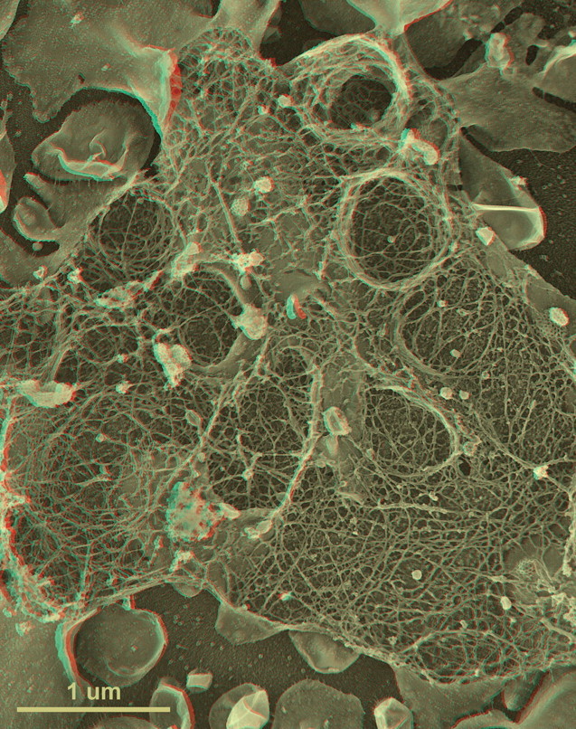
First-time published image of a brand new variation of the QF-DE-RR procedure for imaging the interiors of unroofed cells, which involves doing everything on a pre-formed carbon substrate rather than on glass, so that the platinum replica does not ever need to be separated from its substrate before TEM viewing. This eliminates the huge problem of replica breakage that has always plagued the field – the breakage occurring when the replica is separated from the underlying cells and substrate, in order to be viewed in the TEM. Also, because freeze-fracture replicas were always so fragile, they formerly had to be supported by carbon films deposited on top of them, which tended to confuse or obscure the final images. Now, with the carbon substrate underneath the cells, this ‘backing’ or support film can be eliminated, and vastly larger and more stable replicas can be obtained, even so. This permits approaches possible never before, as in this experiment, where HeLa cells that were in suspension culture, and thus were highly ‘blebby’, were exposed to glow-discharged carbon and allowed to attach to it for only 1 min before they were ‘unroofed’, thereby yielding images of the inside surface of such highly dynamic cell processes as blebs (the obvious, micron-sized circular domains in the cell) where actin polymerization is known to be going on actively [168,169] but could never before be visualized at this resolution. Close inspection of the circular domains illustrates that actin polymerization in situ is via the formation of y-shaped branches from the existing actin filaments, exactly as was predicted from the ‘dendritic branching’ model we derived earlier from our in vitro imaging of actin and Arp2/3 [170].
Fig. 5.
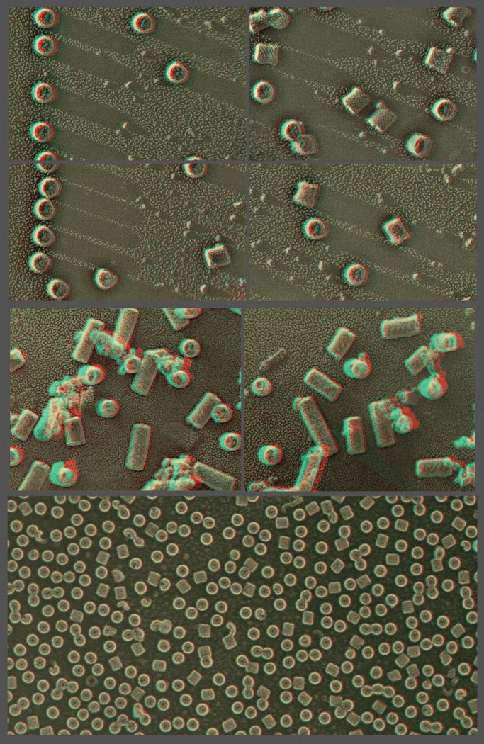
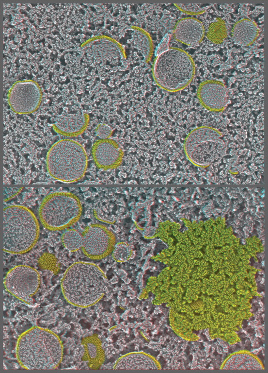
Illustration of the three basic approaches to in vitro imaging of macromolecules permitted by QF-DE-RR, using molluscan hemocyanin as an example. This barrel-shaped didecamer (molecular weight ∼4 mDa) appears in replicas as having a diameter of ∼28 nm and normally a length of ∼30 nm (except in certain snails, as in the central panel, where lengths are multiples of the 30 nm didecamer). Classical ‘shadow casting’ of platinum from a fixed angle (11° above the horizontal in the upper panels) yields dramatic shadows whose lengths are direct measures of the hemocyanin's elevation above the mica. The newer approach of rotary replication with platinum (center and lower panels) yields better overall delineation of surface architecture, in this case showing the basic helical construction of hemocyanin particularly clearly in molecules loosely adsorbed to mica flakes (center panels, derived from our original 1983 introduction of this procedure) [171]. More recently, we have learned that the carbon substrate approach described in Fig. 4 also works extremely well for molecules as well as for cells and cell derivatives, allowing controlled adsorption of nearly anything, almost as on a Biacore SPR chip. Shown on the lower panel is how uniformly such spreads of molecules can be made on carbon, which makes them particularly suitable for contemporary single-particle analyses.
A note on alternative methods of platinum-replicating samples on hard substrates, such as critical point drying
Because few investigators have availed themselves of the opportunity to freeze samples by ultra-rapid cooling against a metal block, alternative strategies have proliferated for obtaining the same sorts of replicas of samples adsorbed to solid surfaces, whether the samples are whole cells or cell derivatives or purified macromolecules. Some years ago, Dan Branton developed an ingenious technique for air-drying molecules suspended in sprayed droplets of glycerol [23,38–40], a technique that became quite widely used because glycerol droplets conveniently recede and leave the macromolecules nearly ‘high and dry’ on the substrate, with minimal distortion from surface-tension effects [41,42]. However, chronic problems with residual glycerol clinging to the molecules ultimately doomed this technique. The method widely used today as an alternative to freeze-drying is critical point drying, a technique perfected especially by Tatyana Svitkina et al. [43–45]. Their TEM images of critical point-dried materials look remarkably similar to our images of freeze-dried samples. However, the technique of critical point drying requires that samples be immersed in liquid CO2, so they must be dehydrated with alcohol in order to substitute the liquid CO2, which means that the samples must be chemically fixed in order to withstand alcohol dehydration. Thus, one of the great advantages of the ‘quick-freeze, deep-etch’ approach is lost with critical point drying – the opportunity to image unfixed samples using the TEM. For this reason alone (not to mention the need to generate platinum replicas of critical point-dried material at room temperature rather than at −100°C, which leads to increased granularity of the platinum replica, hence reduced resolution), we still strongly advocate quick-freezing and freeze-drying over chemical fixation, dehydration and critical point drying. Nevertheless, the latter technique yields very good results in proper hands [46–49] and thus fully substantiates the results of ‘deep-etch’ EM. Besides this, it offers a better bridge to high-resolution SEM, where critical point drying is standard.
History of ultra-rapid freezing by ‘slamming’ against a cold metal block
Years before the advent of high-pressure freezing, we realized that we needed to avoid the use of chemical fixation and antifreezes in order to properly study synaptic vesicle exocytosis and recycling at the frog neuromuscular junction. A colleague of Moor's named Klaus Peper had shown that the frog neuromuscular junction would be an ideal substrate for freeze-fracturing [50,51], and this preparation was the same as that used by Sir Bernard Katz to first observe the ‘quantal’ nature of neurosecretion, for which he had won the Nobel Prize [52]. As a post-doc project in Katz's laboratory, we were asked to obtain convincing ultrastructural evidence that neurotransmitter ‘quanta’ originate from exocytosis of individual synaptic vesicles [53]. Unfortunately, all our efforts to capture this event by chemical fixation and thin-sectioning turned out to be ambiguous, to say the least [54] (Fig. 1). (In retrospect, this should not have been surprising, since neurotransmitter quanta discharge in a fraction of a millisecond [55], while chemical fixation proceeds at a leisurely pace ranging from seconds to minutes.) We thus realized that we had to develop freezing techniques that would be fast enough to capture synaptic vesicle exocytosis on its own time-scale. The only method available at the time (and the only method that we thought might be amenable to freeze-fracturing, as well) was the ‘slam-freezing’ technique developed by van Harreveld et al. at Caltech [56–58]. This involved abrupt application of a living piece of tissue to a highly conductive block of metal (usually copper or silver), which van Harreveld held at liquid nitrogen temperatures (−196°C). We realized that this ‘slamming’ onto metal was strictly one-sided freezing, and it could not possibly be expected to freeze a whole frog muscle all the way through, but we reasoned that if we could achieve freezing fast enough on the side that struck the cold block, and if we could freeze-fracture into the neuromuscular junctions very close to that side, we might obtain samples that had been frozen fast enough to exhibit exocytosis. This indeed worked [2,3,59–61], and our images of synaptic vesicle exocytosis at the frog neuromuscular junction remain, even today, the only definitive proof of Katz's ‘vesicle hypothesis’. Many light microscopic studies using ingenious fluorescent tracers in or on synaptic vesicles have provided additional support for his hypothesis [62–64], but, of course, these all remain necessarily indirect.
Fig. 1.
Classical freeze-fracturing of the frog neuromuscular junction, circa 1974 [54], showing the elongated presynaptic nerve terminal (pale green) punctuated every micron or so by transverse bands (orange) which represent the presynaptic ‘active zones’ where synaptic vesicles undergo exocytosis (captured as a great abundance of ‘pores’ adjacent to IMPs that likely represent voltage-activated calcium channels). The nerve terminal is surrounded by Schwann cells (purple) and is separated by the synaptic cleft (blue) from the surface of the muscle fiber (dark green). This sample was chemically fixed during nerve stimulation, impregnated with antifreeze (25% glycerol), and slowly frozen by ‘quenching’ in Freon 22 before freeze-fracturing and unidirectional ‘shadow casting’ with platinum. This was the standard approach used before the ‘quick-freeze’ technique was invented. A few years after having learning how to generate such images, we developed a liquid helium-cooled ‘Cryopress’ slam-freezer [3], which made it possible to obtain comparable freeze-fracture images of nerves that received only one single stimulus and were then ‘quick-frozen’ immediately thereafter. This permitted us to capture individual synaptic vesicle openings at the presynaptic “active zones” more definitively, and then to correlate their exact abundance with the number of transmitter quanta that had been discharged, thus proving Katz's vesicle hypothesis [52].
In practice, we found that we could obtain ‘better’ freezing (i.e. smaller ice crystals, only beginning to be noticeable at greater depths) if we cooled the copper block even further, down below the liquid nitrogen temperature that van Harreveld used [65], all the way to liquid helium temperature (−269°C) [2,3] (see also [66]). Indeed, we still advocate liquid helium cooling today, in modern versions of the technique. However, there is no strong theoretical reason that it should be better, since the fundamental limiting factor in freezing living biological tissues is how fast heat can be withdrawn from the water in the tissues. (The heat capacity of water is so high and its heat conductivity is so low that the Sun was able to slowly heat the oceans of the Earth and thereby make life possible on this planet. It is not easy to reverse that process!) In contrast, the cold block of copper is so much greater in mass (and in heat capacity) than that of the biological tissue that it probably does not warm up much during the cooling, and so its temperature is pretty irrelevant. In fact, we think these days that liquid helium works better than liquid nitrogen for trivial reasons having to do with issues such as keeping frozen air and water vapor off of the cold block, which may work better when the block is cooled with liquid helium rather than with liquid nitrogen.
We often worry that our advocacy of the use of liquid helium for such ultra-rapid ‘slam-freezing’ has perhaps been the biggest hurdle to its broader acceptance by the field, since liquid helium is relatively expensive everywhere (and is prohibitively expensive or totally unavailable in some countries). Moreover, people worry that liquid helium might be dangerous to handle in a biological laboratory. On this point, we can state categorically that it is not. For more than 30 years, we have had people at all skill levels, from rank beginners to the most skilled technicians in the laboratory, using liquid helium for cooling the ‘slammer’ without a single accident – not even one frostbitten finger. Unlike the tricky propane or ethane gasses that are liquefied with liquid nitrogen and then used for ‘quench-freezing’, liquid helium is utterly non-flammable and is supplied in Dewars that are simply loaded with safety devices to prevent any over-pressurization or any danger of explosion.
Why ‘slam-freezing’ is the best way to prepare samples for freeze-fracturing
Perhaps the single most important reason for using slam-freezing over other methods of freezing currently available is that it yields relatively huge areas of high-quality freezing, roughly 10–20 mm2 in dimension, each and every time. (Note that we say area and not volume, because the quality of freezing declines rapidly and progressively from the surface of the sample that actually comes into direct contact with the copper block, where it is essentially ice-crystal-free, so that by 10 μm under the surface, ice crystals become large enough to seriously disrupt ultrastructural study. Still, the whole surface of the sample is frozen equally, and this surface can be as large as 20 mm2. Moreover, this surface is utterly flat due to its impact against the copper block. Thus, it is a perfect substrate for freeze-fracturing, as is usually done with Moor's lovely old cryomicrotome in a Balzers freeze-etch machine. The microtome knife can be carefully swept across this vast, flat plane of quality freezing, and only the most superficial bits of ice can be removed. (Often, these most superficial fractions of a micron are partially air-dried due to the few seconds of exposure that elapse between mounting of the sample on the ‘freezing-head’ and transferring of this ‘head’ to the plunger that will drop down onto the copper block.) Thus, replicas of incredibly broad areas of well-frozen material can be obtained, and they are often too large to put on a single EM grid. These can be compared with the minute pieces of tissues that can be well frozen with high-pressure freezers, typically 0.5 mm on the side – which are not accessible for freeze-fracturing anyway, because they have to be enclosed in narrow copper tubes or tiny copper planchettes in order to withstand the abrupt application of high pressure.
It is worth mentioning here that to our knowledge, there is no moment during ‘slam-freezing’ that the biological sample experiences any exposure to high pressure, although it is worth considering this possibility when attempting to understand why freezing is always so good on the surface. The reason for this is that the freezing machine is designed to mechanically ‘yield’ or dampen the blow immediately upon impact against the copper block, and also that the sample is supported underneath by a cushiony sponge of some sort – usually a thin slab of aldehyde-fixed lung or liver from some small laboratory-animal that has been sacrificed for other studies. This natural ‘sponge’ compresses immediately upon impact and thereby absorbs any pressure that might be developed by the ‘slamming’ and the resultant flattening of the sample's surface. Finally, the chamber of the freezing ‘head’ is larger in volume than the sample itself, so the sample never fills the chamber, not even when it is flattened. (For comparison, we should mention here that we have recently patented a high-pressure ‘slammer’ that specifically avoids this gentleness and traps the sample inside a very tightly confining chamber at the moment of impact against the copper block, thus totally preventing its expansion into cubic ice and achieving ideal freezing throughout. However, the biological samples frozen with this new device are subjected to such huge pressures (>8000 atm), and are so confined, that they cannot be freeze-fractured without actually exploding at the vitreous-to-hexagonal ice transition temperature of −135°C.) To date, we have not figured out how to avoid this.
Alternative methods of freezing available today, part I: ‘quench-freezing’
It would be incorrect to claim that normal-pressure ‘slam-freezing’ achieves the truly vitreous state of ice, even on the immediate surface that strikes the cold block of copper. In fact, there is no unambiguous way to determine how good the freezing is, even there. All we can say for certain is that if ice crystals are present on the surface, they are below the resolution of the platinum replicas generated (<3 nm). The only technique of freezing that has ever been proven to yield truly vitrified samples is‘quench-freezing’ or ‘plunge-freezing’ of thin films, initiated by Hoerr way back in the 1930s [67], but fully developed for EM by Adrian and Dubochet [68–70]. This is, of course, being used routinely even today for all cryo-EM single-particle analyses [71,72]. This procedure involves blotting of an aqueous film spread on an EM grid to a thickness of ∼0.1 μm and then abruptly plunging it into a cold organic liquid, such as liquid propane or liquid ethane or new mixtures [71]. How fast thin films get frozen in this situation is unknown, but because all the frozen films that result from it measure sub-microns in thickness, they can easily be penetrated by the electron beam of a TEM and are thus amendable to electron diffraction, which proves that they are truly vitrified. (That is, they are composed of amorphous or non-crystalline ice, equal in structure and density to supercooled water.) Since these samples can be imaged using a cryo-EM below the transition point of vitreous ice (−135°C at atmospheric pressure), they yield ideal images of the substance originally suspended in the thin films, images that are truly undistorted by any ice-crystal formation. This is what has made single-particle analysis such a powerful technique in modern electron microscopy.
Unfortunately, this thin-film technique works only for biological samples that are small enough to fit entirely into the films [73]. Larger entities such as whole cells are too thick to be penetrated by the electron beam, except in their thinnest peripheries, and to our knowledge, there has never been any proper analysis done on the condition of the ice in and around these entities after ‘quench-freezing’. Nevertheless, when whole cells are grown on thin carbon films supported on EM grids, they can and do yield ideal images of their thinner regions in the cryo-EM [74–77]. These samples look essentially ice-crystal-free, although the ice around them is too thick to carry out proper electron diffraction to prove this.
What everyone agrees does not work is trying to ‘plunge-freeze’ cell monolayers grown on normal substrates such as glass and plastic. The reason for this is that their substrates are so thick (and have such poor thermal conductivity) that the cultures do not cool at all well from the cell-attached sides, and cooling becomes basically one sided, much like ‘slamming’ against a copper block. But cryogenic liquids have less than one ten-thousandth the heat conductivity and heat capacity of metals, so this sort of ‘one-sided’ heat removal becomes much too slow to freeze cell monolayers. Ice crystals on the ventral, substrate-attached sides of the cells invariably grow to grossly distorting proportions before the freezing is complete. Importantly, an ingenious way around this impasse was proposed by Heinz Horstmann and coworkers at the MPI in Heidelberg in the early 1990s [78]. It involved growing cells on thin wafers of synthetic sapphire instead of on glass. These sapphire wafers are hundreds of times thicker than carbon films on grids, so one would not expect them to support adequate ‘quench-freezing’; but they have such a high thermal conductivity (>10,000× the conductivity of glass) that they apparently do permit cooling from both sides, at least as well as can be judged from the vastly improved quality of freezing that Horstmann et al. achieved on the ventral, sapphire-attached sides of their cell monolayers grown on sapphire. (This useful ‘trick’ seems to have been forgotten by the current manufacturers of contemporary freezing machines, but it certainly should be resurrected.)
Alternative methods of freezing available today, part II: ‘high-pressure’ freezing
Besides mechanizing freeze-fracturing in its early days, Hans Moor and colleagues advanced the field profoundly in another way, by developing high-pressure freezing techniques that would yield essentially ice-crystal-free freezing of relatively large samples – even up to small pieces of whole tissues – without the need of any sort of cryoprotectants [79–81]. Again, they did this initially via their collaboration with Balzers, Inc., of Lichtenstein. Since then, a variant of their approach has been developed by Studer et al., working with Leica Microsystems [82]. The reasoning of all these developers was that if a biological sample could be put under sufficiently high pressures immediately before and during its freezing (>2000 atm), ice crystals would not form because the aqueous environment within the sample would be brought to a point on the phase diagram of water where only the vitreous state exists [83,84]. In simple terms, this could be thought of as freezing in a manner that does not permit the growing solid phase (the ice) to expand into hexagonal crystals [85], since these crystals are actually 10% greater in volume than liquid water (which explains why ordinary ice floats in water – because its density is 10% lower than that of water).
Whether Moor, Studer and their followers actually achieved true vitrification of such thicker samples has never been established. This would require performing X-ray diffraction or electron diffraction on them, but they end up totally encased in the metal containers used for the high-pressure freezing. In any case, the very high quality of the cryo-thin sections that experts have learned to make from such high-pressure frozen samples (see the article by Peters in this 60th Anniversary Issue) would suggest that high-pressure freezing does accomplish the goal of keeping ice crystals below the resolution of the images that can be obtained (∼4 nm).
The only other way to view such high-pressure frozen samples, besides cryo-thin-sectioning [175], is to freeze-substitute them, embed them in plastic and thin-section them. This is standardly done in many laboratories, with obvious success. However, this involves substituting the frozen samples way above the ice-recrystallization point of −135°C, typically starting at −90°C (the melting point of acetone or methanol used to dissolve the ice out of the samples and prepare them for plastic embedding). Hence, freeze substitution would not be expected to yield an accurate representation of the size of any ice crystals that might have been present originally in such high-pressure frozen samples. (To properly justify this assertion, more needs to be said about the process of freeze substitution.)
History of the process of freeze substitution for electron microscopy
Feder and Sidman [86] introduced the technique of freeze substitution in electron microscopy way back in 1956, and van Harreveld and Crowell [56] used it to great advantage in their original developments of freezing by impact against an ultra-cold copper block in 1964, and it remains absolutely critical for the application of EM-tomography to high-pressure frozen samples even today [87]. For all these reasons, it deserves consideration in the context of this review of ‘deep-etch’ EM, even though we use it only as an ancillary technique (see the cover of this 60th Anniversary issue and Figure 6 for examples of our application of freeze-substitution to our ‘slam-frozen’ samples). Again, how (and why) freeze substitution works has long remained another of the wonderful mysteries of our field, ever since its first halting introduction seven decades ago [88]. The substitution fluid has always been acetone or methanol, which is intended to dissolve the ice out of the sample and prepare it for some sort of embedding (either in wax in the early days of the technique [89–92], or in modern plastics today). Fixatives such as aldehydes ± osmium tetroxide ± uranyl acetate are generally added to these solvents to achieve some degree of cross-linking and stabilization of the tissue during substitution, but often these are reduced or omitted entirely when the tissue is to be used for immunocytochemistry [93,94]. In any case, substitution or removal of ice from within and around the tissue cannot begin until the organic solvent is itself in a liquid state. Here then is the problem: the melting point of acetone is −89°C and of methanol is −93°C, but if truly vitrified samples must be brought to these relatively warm temperatures for substitution to begin, they must have to pass through the ice transition-temperature of –135°C, where vitreous ice is thought by most physicists to recrystallize into hexagonal ice [95–97]. Why this apparently does not happen during freeze substitution is indeed a complete mystery! (Likewise, why our slam-frozen samples do not re-crystallize while they are being brought up to fracturing temperature or while they are being deep-etched at −100°C is a total mystery.) Indeed, the mysteries do not stop there, since we have no way of knowing how warm samples get in a cryo-EM during the period when they are being bombarded with electrons. We only know that their darker, more electron-dense regions develop severe bubbles when the electron beam gets too strong. (If this mystery is ever to be understood, what should be done is some ‘time-lapse’ EM imaging of cryosections, or of Dubochet-type thin films, or of the thinner regions of cryopreserved cells, to determine what the transition to hexagonal ice or what other forms of re-crystallization and freeze-drying actually look like in the EM.)
Fig. 6.
Freeze substitution and plastic thin-sectioning samples frozen with our ‘Cryopress’ illustrates how good freezing can be (but only in the uppermost layer of cells that come into direct contact with the liquid helium-cooled copper block). The upper two fields in the figure show sections, about a half-micron apart, of a cultured cell infected with vaccinia virus that was serially sectioned, and the left section is enlarged below to illustrate the characteristic poxvirus factories of cytoplasmic DNA (highlighted in yellow) surrounded by dark spherical virions in various stages of maturation and compaction. Barely visible at this low magnification are numerous granular deposits of proteins and lipids that are depots for supporting the growing, initially crescent-shaped membranous envelopes of the viruses (highlighted in green). Without nearly perfect freezing, none of these cytoplasmic inclusions and differentiations could be properly distinguished nor could viral morphogenesis be properly determined.
In any case, it is not at all clear why samples do not de-vitrify or re-crystallize during freeze substitution, which is usually carried out by leaving the sample at around −80°C for days. Regardless of this, the quality of the results that can be obtained with this technique attest to the fact that somehow ice crystals stay small enough and/or the spaces in which they reside collapse back down as the ice is removed, so as to become imperceptible in the final images. The point is that freeze substitution works and yields images generally better than traditional fixation, and when applied to our slam-frozen samples, it yields huge areas of good freezing – but also shows us exactly how fast this good freezing deteriorates with distance away from the surface that hit the copper block. This gradual worsening of freezing and increasing size of distorting ice crystals provides us with a painful reminder of the limitations of normal-pressure freezing, but it correlates well with the signs of ice crystal damage we see in our replicas when we freeze-fracture tissues at progressively greater depths. We cannot spell out here all the different protocols of freeze substitution advocated today or compare and critique them. Suffice to say that in our case, with only 10 μm of good freezing to work with in the first place, but with a huge flat surface for exchange or substitution, we can carry out the procedure in hours rather than in days and find that agitation of the sample during substitution even allows us to reduce the time to minutes (simply by removing the frozen sample from LN2 and letting it warm up on a shaker on the lab bench) (Fig. 6). Feder and Sidman or van Harreveld and Crowell would be shocked to hear this, since when they pioneered the technique, they advocated a minimum of 2 days to accomplish the substitution, and modern commercial devices for freeze substitution often take even longer times.
Personal reminiscences on the ‘heyday’ of deep-etch EM
Once our basic protocol was established, that of ultra-fast freezing by ‘slamming’ against a copper block, followed by freeze-fracturing, deep-etching and platinum replication inside a dedicated Balzers apparatus, we entered a period that could safely be described as our ‘heyday’. We were joined at that time (1979 onwards) by a young post-doc named Nobutaka Hirokawa, who quickly became the leading practitioner of this art and skillfully applied it to a wide range of problems in cell biology [98–100,176]. During his tenure in the laboratory, Hirokawa was supported by the Muscular Dystrophy Association of America, holding its highly prestigious George Meany postdoctoral fellowship. He promptly established in-depth collaborations with many leading cell biologists of the day, most notably with Louis Tilney, who was one of the brightest stars to emerge from Keith Porter's original cadre of EM trainees and who went on to have a long and productive career, most notably in the study of actin dynamics [101–104]. Together with Tilney and others, Hirokawa skillfully used deep-etch EM to map the structure of actin and all the other important cytoskeletal components in a number of important tissues (nerve, liver, gut, sperm, etc.) and then developed methods for performing immunocytochemistry via deep-etch EM and ultimately for performing molecular imaging using deep-etch EM. These successes led to Hirokawa's being recruited directly from post-doc to Associate Professor at our institution, but we could not keep him there for long, as he was asked within a year to return to the University of Tokyo Faculty of Medicine as the Chairman of the Department of Anatomy and Cell Biology. At Tokyo University, Hirokawa continued his outstanding work in deep-etch EM, until he came upon the broad family of kinesin-related proteins and his work took off in a multitude of other important new directions [105–109].
Other gifted and active deep-etch EM practitioners in the laboratory during its ‘heyday’ included Doug Chandler (now at the University of Arizona), Wallace Ip (now at the University of Cincinnati), Eisaku Katayama (now at Tokyo University), Cliff Harding (now at Case Western Reserve University) and, notably, Ursula Goodenough (long at Washington University, who along with Heuser used deep-etch EM to uncover the basic structure and organization of dynein molecules in cilia and flagella [110–113]). Taken together, the combined efforts of all these practitioners established the utility of the ‘deep-etch’ EM technique over a broad range of problems in cell biology and established it permanently in the armamentaria of techniques used in electron microscopy. Over 50 Balzers freeze-etch machines were garnered by Japanese Universities alone, and a large number of these were also used to do outstanding work in ‘deep-etching’ as well as to perform more traditional forms of freeze-fracturing. This was nicely reviewed by Hirokawa in 1989 [100].
Enter the ‘perfectionists’
Every field breeds a few individuals who, due to their basic nature, are compelled to push its technical limits to the maximum and to seek the highest quality data. So too with freeze-etch EM, where a major follower of Hans Moor in Zurich, Heinz Gross, devoted his career to absolutely perfecting the production of platinum replicas, by engineering fantastic high-vacuum evaporators that permitted ultra-clean and ultra-low temperature replica production [114–116]. No replicas ever exceeded Gross's in terms of their perfect clarity and cleanliness.
Only one man chose to follow his lead and carry it further. That man was Toku Kanaseki at the Tokyo Metropolitan Institute of Neurology. Kanaseki had already discovered the ‘honeycomb’ organization of the clathrin coats on endocytotic vesicles [177] and thus had established himself in the upper echelons of electron microscopists, but he was not content with this and sought to uncover further structural marvels by acquiring a duplicate of Heinz Gross's ultra-high-vacuum evaporator, the Balzers UMS 500P, which he used for years in Tokyo to generate all sorts of gorgeous replicas of all sorts of biological preparations. Unfortunately, the wealth of beautiful freeze-etch data that Kanaseki generated using this ‘ultra-high-vacuum’ approach may never be fully appreciated, because he published so little of it. A tantalizing subset of his works may be found in [117–122].
Dramatically opposite in temperament (and output) was another genius of the technique, Harold Erickson, who published scores of papers on the fine structure of platinum-replicated molecules, which he generated by the more conventional means of air-drying aerosols of molecules suspended in glycerol and then freeze-drying and replicat in the molecules in a normal vacuum. This was the technique that Branton had originally championed but did not pursue for long. However, in Harold Erickson's hands, due to his complete grasp of physical biochemistry as well as his deep understanding of basic cell biology (plus his innate ‘good eye’), his replicas will always remain matchless in terms of their clarity and definitiveness (and thus, matchless in terms of their information content concerning all sorts of macromolecular structures). A small subset of Erickson's valuable works in the field of molecular imaging via platinum replication can be found in references [41,42,123–130].
Directions for future improvements in deep-etch EM
Several technical problems with the whole approach of ‘deep-etch’ EM have been alluded to above, and their possible solutions are discussed here. Foremost is the need today for a commercially available ‘slammer’ and for a contemporary freeze-etch machine that is specifically designed to handle the frozen samples that derive from it. The classic Balzers freeze-etch machines are no longer made, and today's commercial freeze-etch machines are not designed to properly handle slam-frozen samples. Recently, a few homemade versions of our freeze-etch machine have been produced and have been disseminated, and the few laboratories that have them have individually modified their freeze-etch machines in order to handle the large samples that emerge from them, but no systematic effort to create the proper amalgamation has been attempted. As with Hans Moor's introduction of the first Balzers freeze-etch machine, such an effort would make the ‘deep-etch’ technique available to all and would greatly stimulate its further development.
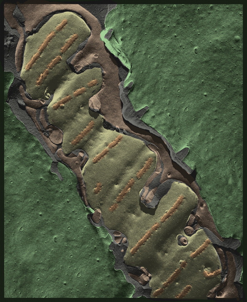
Additionally, we can properly hope to witness in the coming years the development of valuable alternatives to freeze-fracturing for gaining access to the interior of cells – most particularly, the procedure of focused-ion-beam milling, which when carried out with gallium ions could have an accuracy of ±5 nm [131] and could be directed so as to remove precisely as much material from the surface of a frozen sample as desired [132,133]. This would be quite an improvement over standard freeze-fracturing, which remains a very hit-or-miss affair – even with the best of the cryomicrotomes available today. See Fig. 7 for particularly successful fractures into vaccinia virus-infected cells, comparable to ultrathin plastic-sections of the same material shown in Fig. 6. Focused-ion-beam milling of quick-frozen samples would hopefully yield preparations that were entirely equivalent to those used in the new procedure of ‘ion-abrasion SEM’ [134–138] but would permit their visualization at the higher resolution of the TEM.
Fig. 7.
Platinum replica of freeze-fractures through cells infected with vaccinia virus and then quick-frozen, exactly as was done in Fig. 6, permit imaging of individual viruses in their cytoplasmic context, at much higher magnification. This illustrates that the developing poxvirus crescents, as well as the complete spheres, have a distinctive geodetic [172] or ‘honeycomb’ scaffold on their external surface, not unlike the lattices on clathrin-coated vesicles (Fig. 3) but more than twice as fine (only 7 mm vertex to vertex). This lattice is highlighted in yellow to illustrate how freeze-fracturing breaks through it and travels along the bumpy membrane of the developing virion (the dome-shaped examples) or ‘cross-fractures’ the virions to expose their inner core of protein and DNA (the flatter examples). One of the granular ‘supply depots’ of membrane and protein for making the envelopes of these virions, which are barely visible as the green-highlighted entities in Fig. 6, is seen distinctly in the lower panel (it is highlighted in green). It is composed of a scrambled collection of 7 mm granules that we have shown in earlier work [147,148] to represent trimers of a 63 kDa self-assembling coat protein (made by the ORF ‘D-13 L’ in vaccinia nomenclature). Comparison of the granular texture of this viral inclusion with the rest of the surrounding cytoplasm illustrates why QF-DE-RR is a particularly useful technique for discerning and mapping all kinds of cytoplasmic inclusions in health and disease: (i) the imaging is unperturbed by any chemical cross-linking or dehydration; (ii) it does not require any differential staining of the substances in the inclusion and (iii) it relies entirely on the natural surface texture of the inclusion, which is readily apparent in such 3D views.
Alternatively, there is no a priori reason why a ‘slam-frozen’ sample cannot be mounted in a cryo-ultramicrotome so that its surface can be skimmed off precisely, before deep-etching and platinum replication. Paul Walther in Ulm has published his preliminary efforts to do just this [139–141]. Cryotransfer devices between the two instruments would need to be devised, but the prototypes of such devices are already available for commercial cryo-SEMs. We have further demonstrated the feasibility of this general approach by recently developing a method to successfully platinum-replicate immunogold-decorated ultra-microtome cryosections that have been prepared by the so-called Tokuyasu technique (the very powerful technique of freezing in concentrated sucrose, followed by cryo-thin-sectioning and thawing of the sections for antibody decoration [142–146]) (Fig. 8). This has shown us that ultramicrotomy with a diamond knife yields a perfectly suitable surface for ‘deep-etching’ and platinum replication, even though it does not create rough freeze-fracturing in the classical sense [147,148] (Fig. 8).
Fig. 3.
View of the inside surface of the plasmalemma of a HELA cell, prepared as in Fig. 2 by ‘unroofing’ a monolayer culture grown on a glass coverslip before quick-freezing and freeze-drying it according to our standard procedures [165]. Here, we focus on the variety of clathrin lattices that are seen on all cells and illustrate the stages in their evolution from totally flat lattices to fully curved ones, ready to pinch off from the cell surface during endocytosis. Such images were the first to illustrate that actin filaments (purple) become involved in the later stages of the budding process, a fact now well established [166,167], and remain behind as circular ‘scars’ after the coated vesicles have left the surface (arrow). The opportunity to view such expanses of the plasma membrane, at such high resolution, was a lucky outcome of being able to freeze at speeds high enough to avoid ice-crystal formation and then rotary replicate with platinum for TEM without melting these quick-frozen samples.
Fig. 8.
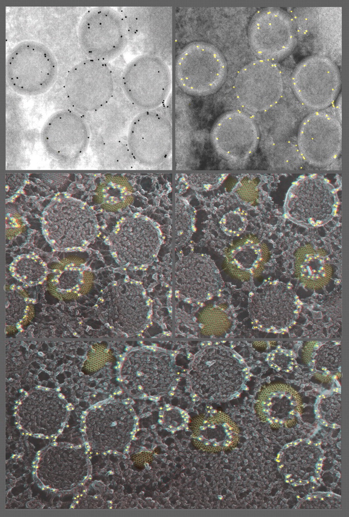
Thawed Tokuyasu cryosections of vaccinia-infected cells decorated with anti-D-13, the honeycomb scaffold protein [148], and imaged using the standard method (upper two panels) or by re-freezing the thawed and decorated cryosection and then freeze-drying and platinum replicating it (lower three panels). In keeping with the fact that nearly anything can be put on a substrate, and then quick-frozen and freeze-dried for platinum replication, a particularly useful application of this is to image Tokuyasu-type immunogold-decorated cryosections. The Tokuyasu technique is widely used and highly successful [142–146], but has always suffered from the exceedingly low e-contrast of the sections, making it particularly difficult to discern cellular membranes in any detail. This can be overcome by making ‘deep-etch’ replicas of these sections after they have been antibody- and gold-decorated. This provides remarkably clear 3D information about the location of gold relative to cellular structures. (To make the comparison more obvious, the upper left panel is contrast-reversed in the upper right panel, to make the gold dots look white, as they do in our platinum replicas). (Actually, all the white dots have been artificially highlighted yellow here, for ease of interpretation.) Readily apparent in the 3D views of the platinum replicas, below is that the ‘honeycomb’ lattice labels only on its uppermost cut edges, where apparently the D13 epitope must be exposed. This immediately explains why earlier Tokuyasu cryosection EM with anti-D-13 antibodies incorrectly assigned this protein to an internal location in the virion [173]. (Note how the left-most virion in the upper panel would seem to suggest this.) Namely, all the virions that are just barely cut open (e.g. are ‘scalped’), or are otherwise not cut exactly through their equators during the cryosectioning, stain only on their uppermost cut edges, which are invariably inside the widest circumference of the virion. The lack of this 3D information, plus the lack of clear-cut imaging of the surfaces of membranes in Tokuyasu cryosections, can lead to such misinterpretations.
Besides such improvements in dissecting, accessing, or cutting into the immediate interiors of slam-frozen samples where their freezing is the very best, we can also hope to witness the development in the next few years of SEMs that can truly reach the resolution of our current replicas, which would mean that we could fully circumvent the current requirement to clean the biological material away from beneath the replica so that it can be penetrated by the beam of the TEM. This cleaning step almost invariably damages the replica and often shatters it into myriads of tiny pieces, making the TEM analysis much more difficult. (See Fig. 4 for a new method we are currently working on for partially overcoming this problem.) Moreover, we can hope that SEMs will soon be able to achieve the same level of resolution on uncoated samples that remain frozen in the microscope, just as soon as means are devised for preventing the loss in clarity that results from sample-charging and from excessive penetration of the electron beam into the ice. When that magical day arrives, we will finally be able to observe freeze-fractured and ‘deep-etched’ samples without ever exposing them to the withering beam of the platinum evaporator! And combining these advances, we presume that the day will come when one can image the true surface of a ‘slam-frozen’ sample and then cut progressively into it via ion-beam milling or ultramicrotomy to image successively greater depths within it. This would finally allow a proper evaluation of how fast its ‘quality’ freezing declines and, ultimately, would allow the development of improved freezing methods, in general.
Moreover, we can hope to witness in the near future the introduction of new procedures for precisely controlling the vacuum sublimation of ice from these cut surfaces (e.g. the freeze-etching or ‘deep-etching’ step) – procedures such as controlled infrared surface heating or focused ion beam or electron-beam etching or sputtering. This would allow precise control over how much topological relief is being revealed on the precision-cut surfaces of the sample and would vastly improve the current situation, where the only variable that can be manipulated in today's freeze-etch machines is the basic temperature of the cryo-stage on which the sample is mounted. The effect of this manipulation on etching parameters is very crude and approximate, as it depends greatly on how firmly the sample is thermally coupled to the stage, as well as on the overall vacuum conditions in the machine and the amount of water vapor in the vacuum, etc. This gives us very limited control over the extent of etching we achieve and renders this critical step in the procedure a very ‘hit-or-miss’ affair as well. Finally, we can reasonably look forward to significant improvements in the electron-beam guns that generate platinum replicas, to the point that someday they should be able to properly handle higher melting-point metals such as tantalum and tungsten, without imposing excessive heat loads on the frozen samples, and thus can achieve more finely-grained replicas, and we can hope that someday these ‘guns’ will even be able to shield our frozen samples from all radiant (photon) heating while still allowing the evaporative deposition of metals onto their surfaces. (Here, we can imagine that beam splitters or deflection coils could be devised, which would redirect the evaporated metal onto the surface of the sample while allowing the blazingly hot emitted photons to pass right by it.)
3D Electron microscopy – yesterday, today and tomorrow
The replicas generated by deep-etch EM are ideal samples for 3D viewing, since they are essentially opaque ‘masks’ that reflect the underlying topology of the molecules and membranes that are partially emerging from ice. From the earliest days, we have, therefore, presented them in 3D in all our publications and lectures, originally as black-and-white stereo pairs, when publishing color prints in scientific journals was prohibitively expensive, and more recently, as color prints have become standard in modern journals, as 3D ‘anaglyphs’ (e.g. superimposed stereo pairs where the left image is red and the right image is green, so that viewing them requires R/G glasses). Figures 2–5, 7 and 8 are presented in such “anaglyph” 3D forms in this article, and supplied in higher-resolution versions in the Supplemental Figures. For lectures, on the other hand, we have always superimposed our stereo-pairs onto a single screen. Originally, we did this with two projectors sending images through oppositely oriented polarizing filters onto a silver screen, which required our audiences to wear polarizing glasses like people did while watching the old 3D movies of the 1950s. In this, we were following the lead of the pioneers of high-voltage electron microscopy, Kiyoshi Hama in Japan [149–154] and Keith Porter in the USA [155–159]. These pioneers were the first to obtain high-resolution micrographs of really thick sections or whole mounts of cells, thanks to the great penetrating powers of their high-voltage microscopes. As a consequence, their amazing micrographs contained significant depth information and absolutely required 3D viewing to be interpretable. However, few people could properly view stereo pairs printed in journals, let alone projected through polarizing filters, and we will always fondly remember the consternation and fuss that arose among the audiences who were privileged enough to witness one of Hama's or Porter's classic silver-screen presentations.
All these were rendered obsolete with the advent of digital projectors and computer programs that could properly generate ‘anaglyph’ images with full color separation and saturation. (Our early attempts to present 3D EMs in ‘anaglyph’ form via high-quality 35 mm color films such as Kodachrome were sadly inadequate, as is the CMYK color printing in scientific journals even today – in both cases due to very poor color separation.) This problem was entirely obviated by modern RGB computer screens and projectors, and so we can now recommend that the interested reader download the online supplemental versions of the micrographs presented in this article in a truly proper ‘anaglyph’ 3D form and observe how we prepare them [160]. Such digital ‘anaglyphs’ can be projected onto any screen or wall and provide stunning 3D rendition of the topological relief provided by ‘deep-etch’ replicas. (More difficult to view are anaglyph images of translucent objects such as thick plastic sections or whole mounts – more difficult simply because the human brain is not naturally attuned to observing such semi-transparent objects. Compound this with the eye strain resulting from the awkward color bombardment between the viewers' eyes that results from looking through such disparate red and green filters, and much of the value of 3D viewing is lost on most people).
This remains a significant problem today and one that has been greatly compounded by the rapid advances in EM tomography, which can generate 3D volume sets incredibly more rich in information than the early stereo pairs obtained with the behemoth high-voltage TEMs of yesteryear. How should this volume information be presented to contemporary audiences? The temporary answer has been to generate movies of artificial ‘computer flythroughs’ of these tomographic data sets, as if they had been re-sliced by some magical ultramicrotome (but actually by the computer) into exceedingly thin and contrasty sections, and then observe them as stacks of serial sections, something that microscopists and their followers are already comfortable with viewing. However, this approach does not fully recapitulate or reveal the amazing 3D relationships that exist in such tomographic data sets, so computer-generated surface renderings of ‘segmented’ serial stacks are generally presented along with the flythroughs, and attempts to show 3D relationships in these renderings or models are done, using simple computer-generated rotation of them about one or more axes. This entails an extremely unfortunate loss of 3D information, since translucent entities such as cytoskeletal filaments and phospholipid membranes are rendered as opaque surfaces, almost as if the original biological sample had been ‘plasticized’.
Clearly what is needed in the future, for proper viewing and interpretation of both EM tomographic reconstructions and 3D platinum replicas, is a means of projecting 3D that does not use color filters such as anaglyphs and can properly portray color information as well as topological information. Only then will we be able to color-code different objects in an image to allow the viewer to appreciate their overall extent and their precise interrelationships, as is done for the figures in this article. (This color coding will be done exactly as segmentation is currently done on tomographic data sets or even by direct inspection on our more easily interpretable platinum replicas.) The 3D projection itself will most likely be done by simple application of the circular-polarizing techniques currently being used by modern commercial movie houses, namely alternate projection of left/right images at high frequencies (30–60 Hz) through liquid-crystal polarizers whose axis of polarization is electronically ‘flipped’, by computer control, in precise synchrony with the left/right image alternation. Presently, such technology is available for movie theaters worldwide and is even being tested on the next generation of home TVs. So it will certainly not be long before it is streamlined, and reduced in cost enough, to be brought into the scientific laboratory and the academic lecture hall. Then, audiences will be able to sit back and look deep within the cell and fully appreciate the marvels of its 3D organization. We eagerly await this next advance in the technology of viewing electron microscopic data!
Deep-etch electron microscopy's new opportunity to compliment and inform cryo-EM-tomography
With the rapid development and dissemination of powerful new ways to image unfixed, still frozen cells by EM tomography (as described by others in this Anniversary Issue), the utility of ‘deep-etch’ EM seems greater than ever. The sharp contrast and 3D topology that it provides by TEM provide a ready check for the advanced 3D computer reconstructions generated by tomography, where contrast is initially so low that individual images or stereo pairs cannot provide any discernable structure. Additionally, the simple, relatively ancient procedure of freeze-fracturing permits one to gain easy access to the interiors of samples that can otherwise only be reached by exceedingly difficult procedures such as cryo-thin-sectioning. Undoubtedly, these procedures will be dramatically improved in coming years, just as classical plastic thin-sectioning was steadily improved in the early days of EM. To date, most of the EM tomography is being performed either on freeze-substituted samples (as described above, on samples chemically fixed, dehydrated and embedded – albeit at sub-zero temperatures, which greatly improves the outcome) or on cryo-samples that are intrinsically thin enough to be penetrable by the electron beam – a remarkable throwback to the earliest days of biological TEM before thin-sectioning had been developed, when only the thinnest regions of whole cells could be observed [161,162].
The very thinness of the latter whole-mount samples also means that they are ideal samples for ultra-rapid freezing techniques and can yield essentially ice crystal-free freezing, and so they are also ideal samples for freeze-fracturing and deep-etching. So again, they provide ideal substrates for comparison between techniques and approaches. The future seems bright, then, for a range of approaches for carrying out electron microscopy on all sorts of biological entities frozen ‘direct from life’ and thereby preserved in the most life-like state possible. This already has yielded, and certainly should continue to yield, significant insights into the basic composition (and physical state) of the cytoplasm and all its components, as well as further understanding of the dynamics of intracellular organelles and further understanding of the interactions of man-made materials with living cells. The next 60 years of electron microscopic research should prove to be even more glorious than the past 60 years!
Supplementary data
Supplementary data are available at http://jmicro.oxfordjournals.org/.
Funding
Financial support for this work was long provided by the USPHS, Grant #GM29647, until support was taken over by the World Premier International Research Center Initiative, administered by MEXT (the Ministry of Education, Culture, Sports, Science and Technology) of Japan.
Supplementary Material
ACKNOWLEDGEMENT
This article is dedicated to Thomas S. Reese, Senior investigator, NINDS, NIH, Bethesda, USA, with whom I have worked intimately throughout my entire career. My thoughts and activities have been so totally intertwined with Reese's, throughout, that everything we accomplished was truly mutual. Moreover, my collaboration with Reese was always a primary motivating force, even an inspiration. I am forever grateful to Reese for thus ‘sharing his all’.
References
- 1.Moor H, Muhlethaler K, Waldner H, Frey-Wyssling A. A new freezing-ultramicrotome. J. Biophys. Biochem. Cytol. 1961;10:1–13. doi: 10.1083/jcb.10.1.1. doi:10.1083/jcb.10.1.1. [DOI] [PMC free article] [PubMed] [Google Scholar]
- 2.Heuser J E, Reese T S, Landis D M. Preservation of synaptic structure by rapid freezing. Cold Spring Harb. Symp. Quant. Biol. 1976;40:17–24. doi: 10.1101/sqb.1976.040.01.004. [DOI] [PubMed] [Google Scholar]
- 3.Heuser J E, Reese T S, Dennis M J, Jan Y, Jan L, Evans L. Synaptic vesicle exocytosis captured by quick freezing and correlated with quantal transmitter release. J. Cell. Biol. 1979;81:275–300. doi: 10.1083/jcb.81.2.275. doi:10.1083/jcb.81.2.275. [DOI] [PMC free article] [PubMed] [Google Scholar]
- 4.Heuser J E, Salpeter S R. Organization of acetylcholine receptors in quick-frozen, deep-etched, and rotary-replicated Torpedo postsynaptic membrane. J. Cell. Biol. 1979;82:150–173. doi: 10.1083/jcb.82.1.150. doi:10.1083/jcb.82.1.150. [DOI] [PMC free article] [PubMed] [Google Scholar]
- 5.Heuser J. Three-dimensional visualization of coated vesicle formation in fibroblasts. J. Cell. Biol. 1980;84:560–583. doi: 10.1083/jcb.84.3.560. doi:10.1083/jcb.84.3.560. [DOI] [PMC free article] [PubMed] [Google Scholar]
- 6.Heuser J E. Quick-freeze, deep-etch method of preparing samples for 3-D electron microscopy. Trends Biochem. Sci. 1980;6:64–68. doi:10.1016/0968-0004(81)90024-4. [Google Scholar]
- 7.Heuser J. Preparing biological samples for stereomicroscopy by the quick-freeze, deep-etch, rotary-replication technique. Methods Cell Biol. 1981;22:97–122. doi: 10.1016/s0091-679x(08)61872-5. doi:10.1016/S0091-679X(08)61872-5. [DOI] [PubMed] [Google Scholar]
- 8.Moor H, Mühlethaler K. Fine structure in frozen-etched yeast cells. J. Cell. Biol. 1963;17:609–628. doi: 10.1083/jcb.17.3.609. doi:10.1083/jcb.17.3.609. [DOI] [PMC free article] [PubMed] [Google Scholar]
- 9.Moor H. Use of freeze-etching in the study of biological ultrastructure. Int. Rev. Exp. Pathol. 1966;5:179–216. [PubMed] [Google Scholar]
- 10.Moor H. Freeze-etching. Int. Rev. Cytol. 1969;25:391–412. doi: 10.1016/s0074-7696(08)60209-0. doi:10.1016/S0074-7696(08)60209-0. [DOI] [PubMed] [Google Scholar]
- 11.Williams R C, Wyckoff R W G. The thickness of electron microscope objects. J. Appl. Phys. 1944;15:712. doi:10.1063/1.1707376. [Google Scholar]
- 12.Williams R C, Wyckoff R W G. EM study of elementary particles of viruses. Proc. Soc. Exp. Biol. Med. 1945;58:265. [Google Scholar]
- 13.Williams R C, Wyckoff R W. Electron shadow micrography of the tobacco mosaic virus protein. Science. 1945;101:594–596. doi: 10.1126/science.101.2632.594. doi:10.1126/science.101.2632.594. [DOI] [PubMed] [Google Scholar]
- 14.Price W C, Williams R C, Wyckoff R W. The electron micrography of crystalline plant viruses. Science. 1945;102:277–278. doi: 10.1126/science.102.2646.277. doi:10.1126/science.102.2646.277. [DOI] [PubMed] [Google Scholar]
- 15.Bachmann L, Abermann R, Zingsheim H P. Improved resolution in freeze-etching. Histochemie. 1969;20:133–142. doi: 10.1007/BF00268707. doi:10.1007/BF00268707. [DOI] [PubMed] [Google Scholar]
- 16.Gross H, Muller T, Wildhaber I, Winkler H. High resolution metal replication, quantified by image processing of periodic test specimens. Ultramicroscopy. 1985;16:287–304. doi:10.1016/0304-3991(85)90098-1. [Google Scholar]
- 17.Schnyder T, Gross H, Winkler H, Eppenberger H M, Wallimann T. High-resolution shadowing and image averaging of single molecules and formation of linear filaments under specific staining conditions. J. Cell Biol. 1991;112:95–101. doi: 10.1083/jcb.112.1.95. doi:10.1083/jcb.112.1.95. [DOI] [PMC free article] [PubMed] [Google Scholar]
- 18.Gross J, Schmitt F O. The structure of human skin collagen as studied with the electron microscope. J. Exp. Med. 1948;88:555–568. doi: 10.1084/jem.88.5.555. doi:10.1084/jem.88.5.555. [DOI] [PMC free article] [PubMed] [Google Scholar]
- 19.Gross J. The structure of elastic tissue as studied with the electron microscope. J. Exp. Med. 1949;89:699–708. doi: 10.1084/jem.89.6.699. doi:10.1084/jem.89.6.699. [DOI] [PMC free article] [PubMed] [Google Scholar]
- 20.Highberger J H, Gross J, Schmitt F O. The interaction of mucoprotein with soluble collagen: an electron microscope study. Proc. Natl. Acad. Sci. USA. 1951;37:286–291. doi: 10.1073/pnas.37.5.286. doi:10.1073/pnas.37.5.286. [DOI] [PMC free article] [PubMed] [Google Scholar]
- 21.Fujimoto K. Freeze-fracture replica EM combined with SDS digestion for cytochemical labeling of integral membrane proteins – application to the immunogold labeling of intercellular junctional complexes. J. Cell Sci. 1995;108:3443–3449. doi: 10.1242/jcs.108.11.3443. [DOI] [PubMed] [Google Scholar]
- 22.Rash J E, Yasumura T. Direct immunogold labeling of connexins and aquaporin-4 in freeze-fracture replicas. Cell Tissue Res. 1999;296:307–321. doi: 10.1007/s004410051291. doi:10.1007/s004410051291. [DOI] [PubMed] [Google Scholar]
- 23.Shotton D, Burke B, Branton D. The shape of spectrin molecules from human erythrocyte membranes. Biochim. Biophys. Acta. 1978;536:313–317. doi: 10.1016/0005-2795(78)90079-x. [DOI] [PubMed] [Google Scholar]
- 24.Margaritis L H, Elgsaeter A, Branton D. Rotary replication for freeze-etching. J. Cell. Biol. 1977;72:47–56. doi: 10.1083/jcb.72.1.47. doi:10.1083/jcb.72.1.47. [DOI] [PMC free article] [PubMed] [Google Scholar]
- 25.Shotton D M, Burke B E, Branton D. The molecular structure of human erythrocyte spectrin. J. Mol. Biol. 1979;131:303–329. doi: 10.1016/0022-2836(79)90078-0. doi:10.1016/0022-2836(79)90078-0. [DOI] [PubMed] [Google Scholar]
- 26.Steere R L. Freeze-fracture: a personal history. J. Electron. Microsc. Tech. 1989;13:159–164. doi: 10.1002/jemt.1060130304. doi:10.1002/jemt.1060130304. [DOI] [PubMed] [Google Scholar]
- 27.Steere R L. Electron microscopy of structural detail in frozen biological specimens. J. Biophys. Biochem. Cytol. 1957;3:45–60. doi: 10.1083/jcb.3.1.45. doi:10.1083/jcb.3.1.45. [DOI] [PMC free article] [PubMed] [Google Scholar]
- 28.Steere R L, Erbe E F. Complementary freeze-fracture, freeze-etch specimens. J. Microsc. 1979;117:211–218. doi: 10.1111/j.1365-2818.1979.tb01177.x. [DOI] [PubMed] [Google Scholar]
- 29.Steere R L, Erbe E F, Moseley J M. Prefracture and cold-fracture images of yeast plasma membranes. J. Cell Biol. 1980;86:113–122. doi: 10.1083/jcb.86.1.113. doi:10.1083/jcb.86.1.113. [DOI] [PMC free article] [PubMed] [Google Scholar]
- 30.Bullivant S, Ames A. A simple freeze-fracture replication method for electron microscopy. J. Cell. Biol. 1966;29:435–447. doi: 10.1083/jcb.29.3.435. doi:10.1083/jcb.29.3.435. [DOI] [PMC free article] [PubMed] [Google Scholar]
- 31.Weinstein R S, Bullivant S. The application of freeze-cleaving technics to studies on red blood cell fine structure. Blood. 1967;29:780–789. [PubMed] [Google Scholar]
- 32.Branton D. Fracture faces of frozen membranes. Proc. Natl. Acad. Sci. USA. 1966;55:1048–1056. doi: 10.1073/pnas.55.5.1048. doi:10.1073/pnas.55.5.1048. [DOI] [PMC free article] [PubMed] [Google Scholar]
- 33.Branton D. Fracture faces of frozen myelin. Exp. Cell Res. 1967;45:703–707. doi: 10.1016/0014-4827(67)90175-9. PMID: 5336898 [PubMed - indexed for MEDLINE] doi:10.1016/0014-4827(67)90175-9. [DOI] [PubMed] [Google Scholar]
- 34.Branton D, Bullivant S, Gilula N B, Karnovsky M J, Moor H, Mühlethaler K, Northcote D H, Packer L, Satir B, Satir P, Speth V, Staehlin L A, Steere R L, Weinstein R S. Freeze-etching nomenclature. Science. 1975;190:54–56. doi: 10.1126/science.1166299. doi:10.1126/science.1166299. [DOI] [PubMed] [Google Scholar]
- 35.Singer S J, Nicolson G L. The structure and chemistry of mammalian cell membranes. Am. J. Pathol. 1971;65:427–437. [PMC free article] [PubMed] [Google Scholar]
- 36.Singer S J, Nicolson G L. The fluid mosaic model of the structure of cell membranes. Science. 1972;175:720–731. doi: 10.1126/science.175.4023.720. doi:10.1126/science.175.4023.720. [DOI] [PubMed] [Google Scholar]
- 37.Dempsey G P, Bullivant S. A copper block method for freezing non-cryoprotected tissue to produce ice-crystal-free regions for electron microscopy. II. Evaluation using freeze fracturing with a cryo-ultramicrotome. J. Microsc. 1976;106:261–271. doi: 10.1111/j.1365-2818.1976.tb02406.x. [DOI] [PubMed] [Google Scholar]
- 38.Usukura J, Yamada E. Freeze-etching technique with simple rapid freezing of fresh biological specimen. J. Electron Microsc. (Tokyo) 1980;29:376–382. [PubMed] [Google Scholar]
- 39.Tyler J M, Branton D. Rotary shadowing of extended molecules dried from glycerol. J. Ultrastruct. Res. 1980;71:95–102. doi: 10.1016/s0022-5320(80)90098-2. doi:10.1016/S0022-5320(80)90098-2. [DOI] [PubMed] [Google Scholar]
- 40.Tyler J M, Anderson J M, Branton D. Structural comparison of several actin-binding macromolecules. J. Cell Biol. 1980;85:489–495. doi: 10.1083/jcb.85.2.489. doi:10.1083/jcb.85.2.489. [DOI] [PMC free article] [PubMed] [Google Scholar]
- 41.Fowler W E, Erickson H P. Trinodular structure of fibrinogen: confirmation by both shadowing and negative stain electron microscopy. J. Mol. Biol. 1979;134:241–249. doi: 10.1016/0022-2836(79)90034-2. doi:10.1016/0022-2836(79)90034-2. [DOI] [PubMed] [Google Scholar]
- 42.Brown H R, Erickson H P. Assembly of proteolytically cleaved tubulin. Arch. Biochem. Biophys. 1983;220:46–51. doi: 10.1016/0003-9861(83)90385-5. doi:10.1016/0003-9861(83)90385-5. [DOI] [PubMed] [Google Scholar]
- 43.Svitkina T M, Shevelev A A, Bershadsky A D, Gelfand V I. Cytoskeleton of mouse embryo fibroblasts: electron microscopy of platinum replicas. Eur. J. Cell Biol. 1984;34:64–74. [PubMed] [Google Scholar]
- 44.Svitkina T M, Neyfakh A A, Jr, Bershadsky A D. Actin cytoskeleton of spread fibroblasts appears to assemble at the cell edges. J. Cell Sci. 1986;82:235–248. doi: 10.1242/jcs.82.1.235. [DOI] [PubMed] [Google Scholar]
- 45.Svitkina T M, Verkhovsky A B, Borisy G G. Improved procedures for EM visualization of the cytoskeleton of cultured cells. J. Struct. Biol. 1995;115:290–303. doi: 10.1006/jsbi.1995.1054. doi:10.1006/jsbi.1995.1054. [DOI] [PubMed] [Google Scholar]
- 46.Svitkina T M, Bulanova E A, Chaga O Y, Vignjevic D M, Kojima S, Vasiliev J M, Borisy G G. Mechanism of filopodia initiation by reorganization of a dendritic network. J. Cell Biol. 2003;160:409–421. doi: 10.1083/jcb.200210174. doi:10.1083/jcb.200210174. [DOI] [PMC free article] [PubMed] [Google Scholar]
- 47.Svitkina T M, Borisy G G. Correlative light and electron microscopy studies of cytoskeletal dynamics. In: Celis J, editor. Cell Biology: A Laboratory Handbook. 3rd edn. Elsevier; 2006. pp. 277–285. [Google Scholar]
- 48.Svitkina T. Electron microscopic analysis of the leading edge in migrating cells. Methods Cell Biol. 2007;79:295–319. doi: 10.1016/S0091-679X(06)79012-4. doi:10.1016/S0091-679X(06)79012-4. [DOI] [PubMed] [Google Scholar]
- 49.Yang C, Czech L, Gerboth S, Kojima S, Scita G, Svitkina T. Novel roles of formin mdia2 in lamellipodia and filopodia formation in motile cells. PLoS Biol. 2007;5:e317. doi: 10.1371/journal.pbio.0050317. doi:10.1371/journal.pbio.0050317. [DOI] [PMC free article] [PubMed] [Google Scholar]
- 50.Dreyer F, Peper K, Akert K, Sandri C, Moor H. Ultrastructure of the “active zone” in the frog neuromuscular junction. Brain Res. 1973;62:373–380. doi: 10.1016/0006-8993(73)90699-9. doi:10.1016/0006-8993(73)90699-9. [DOI] [PubMed] [Google Scholar]
- 51.Peper K, Dreyer F, Sandri C, Akert K, Moor H. Structure and ultrastructure of the frog motor endplate: a freeze-etching study. Cell Tissue Res. 1974;149:437–455. doi: 10.1007/BF00223024. [DOI] [PubMed] [Google Scholar]
- 52.Katz B. Quantal mechanism of neural transmitter release. (The Nobel Prize lecture) Science. 1971;173:123–126. doi: 10.1126/science.173.3992.123. [DOI] [PubMed] [Google Scholar]
- 53.del Castillo J, Katz B. Biophysical aspects of neuro-muscular transmission. Prog. Biophys. Biophys. Chem. 1956;6:121–170. [PubMed] [Google Scholar]
- 54.Heuser J E, Reese T S, Landis D M. Functional changes in frog neuromuscular junctions studied with freeze-fracture. J. Neurocytol. 1974;3:109–131. doi: 10.1007/BF01111936. doi:10.1007/BF01111936. [DOI] [PubMed] [Google Scholar]
- 55.Fatt P, Katz B. Spontaneous subthreshold activity at motor nerve endings. J. Physiol. 1952;117:109–128. [PMC free article] [PubMed] [Google Scholar]
- 56.Van Harreveld A, Crowell J. Electron microscopy after rapid freezing on a metal surface and substitution fixation. Anat. Rec. 1964;149:381–385. doi: 10.1002/ar.1091490307. doi:10.1002/ar.1091490307. [DOI] [PubMed] [Google Scholar]
- 57.Van Harreveld A, Crowell J, Malhotra S K. A study of extracellular space in central nervous tissue by freeze-substitution. J. Cell Biol. 1965;25:117–137. doi: 10.1083/jcb.25.1.117. doi:10.1083/jcb.25.1.117. [DOI] [PMC free article] [PubMed] [Google Scholar]
- 58.Van Harreveld A, Trubatch J, Steiner J. Rapid freezing and electron microscopy for the arrest of physiological processes. J. Microsc. 1974;100:189–198. doi: 10.1111/j.1365-2818.1974.tb03928.x. [DOI] [PubMed] [Google Scholar]
- 59.Heuser J E. Ultrafast freezing to capture the structural changes that underlie neuromuscular transmission. In: Rowland L. P., editor. Exploratory Concepts in Muscular Dystrophy. Amsterdam, The Netherlands: ExcerptaMedica; 1976. pp. 215–239. [Google Scholar]
- 60.Heuser J E. Synaptic vesicle exocytosis revealed in quick-frozen frog neuromuscular junctions treated with 4-AP and given a single electrical shock. In: Cowan W M, Ferrandelli J A, editors. Society for Neuroscience Symposia. Vol. II. Bethesda, MD: Society of Neuroscience; 1977. pp. 215–239. [Google Scholar]
- 61.Heuser J E. Quick-freezing evidence in favor of the vesicular hypothesis. Trends Neurosci. 1978;1:80–82. [Google Scholar]
- 62.Gaffield M A, Tabares L, Betz W J. The spatial pattern of exocytosis and post-exocytic mobility of synaptophluorin in mouse motor nerve terminals. J. Physiol. 2009;587:1187–1200. doi: 10.1113/jphysiol.2008.166728. doi:10.1113/jphysiol.2008.166728. [DOI] [PMC free article] [PubMed] [Google Scholar]
- 63.Gaffield M A, Betz W J. Imaging synaptic vesicle exocytosis and endocytosis with FM dyes. Nat. Protocols. 2006;1:2916–2921. doi: 10.1038/nprot.2006.476. doi:10.1038/nprot.2006.476. [DOI] [PubMed] [Google Scholar]
- 64.Rizzoli S O, Richards D A, Betz W J. Monitoring synaptic vesicle recycling in frog motor nerve terminals with FM dyes. J. Neurocytol. 2003;32:539–544. doi: 10.1023/B:NEUR.0000020609.19873.e8. doi:10.1023/B:NEUR.0000020609.19873.e8. [DOI] [PubMed] [Google Scholar]
- 65.Van Harreveld A, Trubatch J. Progression of fusion during rapid freezing for electron microscopy. J. Microsc. 1979;115:243–256. doi: 10.1111/j.1365-2818.1979.tb00176.x. [DOI] [PubMed] [Google Scholar]
- 66.Usukura J, Yamada E, Akahori H, Takahashi H. An improved device for rapid freezing using liquid helium. J. Electron Microsc. 1981;30:214–219. [Google Scholar]
- 67.Hoerr N L. Cytological studies by the Altmann-Gersh freezing-drying method. Anat. Rec. 1936;65:293–317. doi:10.1002/ar.1090650305. [Google Scholar]
- 68.Adrian M, Dubochet J, Lepault J, McDowall A W. Cryo-electron microscopy of viruses. Nature (London) 1984;308:32–36. doi: 10.1038/308032a0. doi:10.1038/308032a0. [DOI] [PubMed] [Google Scholar]
- 69.Dubochet J, Adrian M, Lepault J, McDowall A W. Cryo-electron microscopy of vitrified biological specimens. Trends Biochem. Sci. 1985;10:143–146. doi:10.1016/0968-0004(85)90150-1. [Google Scholar]
- 70.Dubochet J, Adrian M, Chang J-J, Homo J-C, Lepault J, McDowall A W, Schultz P. Cryo-electron microscopy of vitrified specimens. Quart. Rev. Biophys. 1988;21:129–228. doi: 10.1017/s0033583500004297. doi:10.1017/S0033583500004297. [DOI] [PubMed] [Google Scholar]
- 71.Tivol W F, Briegel A, Jensen G J. An improved cryogen for plunge freezing. Microsc. Microanal. 2008;14:375–379. doi: 10.1017/S1431927608080781. [DOI] [PMC free article] [PubMed] [Google Scholar]
- 72.Dobro M J, Melanson L A, Jensen G J, McDowall A W. Plunge freezing for electron cryomicroscopy. Methods Enzymol. 2010;481:63–82. doi: 10.1016/S0076-6879(10)81003-1. doi:10.1016/S0076-6879(10)81003-1. [DOI] [PubMed] [Google Scholar]
- 73.Li Z, Jensen G J. Electron cryotomography: a new view into microbial ultrastructure. Curr. Opin. Microbiol. 2009;12:333–340. doi: 10.1016/j.mib.2009.03.007. doi:10.1016/j.mib.2009.03.007. [DOI] [PMC free article] [PubMed] [Google Scholar]
- 74.Bretschneider T, Jonkman J, Köhler J, Medalia O, Barisic K, Weber I, Stelzer E H, Baumeister W, Gerisch G. Dynamic organization of the actin system in the motile cells of Dictyostelium. J. Muscle Res. Cell Motil. 2002;23:639–649. doi: 10.1023/a:1024455023518. doi:10.1023/A:1024455023518. [DOI] [PubMed] [Google Scholar]
- 75.Medalia O, Beck M, Ecke M, Weber I, Neujahr R, Baumeister W, Gerisch G. Organization of actin networks in intact filopodia. Curr. Biol. 2007;17:79–84. doi: 10.1016/j.cub.2006.11.022. doi:10.1016/j.cub.2006.11.022. [DOI] [PubMed] [Google Scholar]
- 76.Berriman J A, Li S, Hewlett L J, Wasilewski S, Kiskin F N, Carter T, Hannah M J, Rosenthal P B. Structural organization of Weibel-Palade bodies revealed by cryo-EM of vitrified endothelial cells. Proc. Natl. Acad. Sci. USA. 2009;106:17407–17412. doi: 10.1073/pnas.0902977106. doi:10.1073/pnas.0902977106. [DOI] [PMC free article] [PubMed] [Google Scholar]
- 77.Urban E, Jacob S, Nemethova M, Resch G P, Small J V. Electron tomography reveals unbranched networks of actin filaments in lamellipodia. Nat. Cell Biol. 2010;12:429–435. doi: 10.1038/ncb2044. doi:10.1038/ncb2044. [DOI] [PubMed] [Google Scholar]
- 78.Neuhaus E M, Horstmann H, Almers W, Maniak M, Soldati T. Ethane-freezing/methanol-fixation of cell monolayers: a procedure for improved preservation of structure and antigenicity for light and electron microscopies. J. Struct. Biol. 1998;121:326–342. doi: 10.1006/jsbi.1998.3971. doi:10.1006/jsbi.1998.3971. [DOI] [PubMed] [Google Scholar]
- 79.Moor H, Bellin G, Sandri C, Akert K. The influence of high pressure freezing on mammalian nerve tissue. Cell Tissue Res. 1980;209:201–216. doi: 10.1007/BF00237626. [DOI] [PubMed] [Google Scholar]
- 80.Hunziker E B, Herrmann W, Schenk R K, Mueller M, Moor H. Cartilage ultrastructure after high pressure freezing, freeze substitution, and low temperature embedding. J. Cell Biol. 1984;98:267–276. doi: 10.1083/jcb.98.1.267. doi:10.1083/jcb.98.1.267. [DOI] [PMC free article] [PubMed] [Google Scholar]
- 81.Marti R, Wild P, Schraner E M, Mueller M, Moor H. Parathyroid ultrastructure after aldehyde fixation, high-pressure freezing, or microwave irradiation. J. Histochem. Cytochem. 1987;35:1415–1424. doi: 10.1177/35.12.3680934. doi:10.1177/35.12.3680934. [DOI] [PubMed] [Google Scholar]
- 82.Studer D, Graber W, Al Amoudi A, Eggli P. A new approach for cryofixation by high-pressure freezing. J. Microsc. 2001;203:285–294. doi: 10.1046/j.1365-2818.2001.00919.x. doi:10.1046/j.1365-2818.2001.00919.x. [DOI] [PubMed] [Google Scholar]
- 83.Riehle U, Hoechli M. The theory and technique of high pressure freezing. In: Benedetti E L, Favard P., editors. Freeze-etching: Techniques and Applications. Paris: SocieteFrancaise de MicroscopieElectronique; 1973. pp. 31–62. Chapter 5. [Google Scholar]
- 84.Riehle U. Proceedings: high pressure freezing – present outlook. Arzneimittelforschung. 1975;25:453. [PubMed] [Google Scholar]
- 85.Leunissen J L M, Yi H. Self-pressurized rapid freezing (SPRF): a novel cryofixation method for specimen preparation in electron microscopy. J. Microsc. 2009;235:25–35. doi: 10.1111/j.1365-2818.2009.03178.x. doi:10.1111/j.1365-2818.2009.03178.x. [DOI] [PubMed] [Google Scholar]
- 86.Feder N, Sidman R L. Methods and principles of fixation by freeze-substitution. J. Biophys. Biochem. Cytol. 1958;4:593–604. doi: 10.1083/jcb.4.5.593. doi:10.1083/jcb.4.5.593. [DOI] [PMC free article] [PubMed] [Google Scholar]
- 87.Hoenger A, Bouchet-Marquis C. Cellular tomography. Adv. Protein. Chem. Struct. Biol. 2011;82:67–90. doi: 10.1016/B978-0-12-386507-6.00003-8. [DOI] [PubMed] [Google Scholar]
- 88.Simpson W L. An experimental analysis of the Altmann technic of freezing-drying. Anat. Rec. 1941;80:173–189. doi:10.1002/ar.1090800204. [Google Scholar]
- 89.Mendelow H, Hamilton J G. A new technique for rapid freezing and dehydration of tissues for histology and histochemistry. Anat. Rec. 1950;107:443–451. doi: 10.1002/ar.1091070410. doi:10.1002/ar.1091070410. [DOI] [PubMed] [Google Scholar]
- 90.Persson B H. A method for freezing-dehydration of tissues in liquid medium. Acta Soc. Med. Upsaliensis. 1952;67:155–164. [PubMed] [Google Scholar]
- 91.Deitch A D, Godman G C. The application of a freezing-substitution method of fixation to tissue culture preparations. Anat. Rec. 1955;123:1–12. doi: 10.1002/ar.1091230102. doi:10.1002/ar.1091230102. [DOI] [PubMed] [Google Scholar]
- 92.Patten S F, Brown K A. Freeze-solvent substitution technic. Lab. lnvest. 1958;7:209–239. [PubMed] [Google Scholar]
- 93.Hawes P, Netherton C L, Mueller M, Wileman T, Monaghan P. Rapid freeze-substitution preserves membranes in high-pressure frozen tissue culture cells. J. Microsc. 2007;226:182–189. doi: 10.1111/j.1365-2818.2007.01767.x. doi:10.1111/j.1365-2818.2007.01767.x. [DOI] [PubMed] [Google Scholar]
- 94.Hawes P C, Netherton C L, Wileman T E, Monaghan P. The envelope of intracellular African swine fever virus is composed of a single lipid bilayer. J. Virol. 2008;82:7905–7912. doi: 10.1128/JVI.00194-08. doi:10.1128/JVI.00194-08. [DOI] [PMC free article] [PubMed] [Google Scholar]
- 95.Johari G P, Astl G, Mayer E. Enthalpy relaxation of glassy water. J. Chem. Phys. 1990;92:809–810. doi:10.1063/1.458386. [Google Scholar]
- 96.Angell C A. Insights into phases of liquid water from study of its unusual glass-forming properties. Science. 2008;319:582–587. doi: 10.1126/science.1131939. doi:10.1126/science.1131939. [DOI] [PubMed] [Google Scholar]
- 97.Chaplin M. The water molecule, liquid water, hydrogen bonds and water networks. In: Le Bihan D, Fukuyama H, editors. Water, the Forgotten Biological Molecule. Singapore: Pan Stanford Publishing Ltd.; 2011. pp. 3–19. [Google Scholar]
- 98.Hirokawa N, Tilney L G, Fujiwara K, Heuser J E. Organization of actin, myosin, and intermediate filaments in the brush border of intestinal epithelial cells. J. Cell Biol. 1982;94:425–443. doi: 10.1083/jcb.94.2.425. doi:10.1083/jcb.94.2.425. [DOI] [PMC free article] [PubMed] [Google Scholar]
- 99.Hirokawa N. Quick freeze, deep etch of the cytoskeleton. Methods Enzymol. 1986;134:598–612. doi: 10.1016/0076-6879(86)34125-9. doi:10.1016/0076-6879(86)34125-9. [DOI] [PubMed] [Google Scholar]
- 100.Hirokawa N. Quick-freeze, deep-etch electron microscopy. J. Electron. Microsc. (Tokyo) 1989;38(:):S123–S128. [PubMed] [Google Scholar]
- 101.Tilney L G. The role of actin in nonmuscle cell motility. Soc. Gen. Physiol. Ser. 1975;30:339–388. [PubMed] [Google Scholar]
- 102.Tilney L G, Tilney M S, DeRosier D J. Actin filaments, stereocilia, and hair cells: how cells count and measure. Annu. Rev. Cell Biol. 1992;8:257–274. doi: 10.1146/annurev.cb.08.110192.001353. doi:10.1146/annurev.cb.08.110192.001353. [DOI] [PubMed] [Google Scholar]
- 103.Tilney L G, Tilney M S. The wily ways of a parasite: induction of actin assembly by Listeria. Trends Microbiol. 1993;1:25–31. doi: 10.1016/0966-842x(93)90021-i. doi:10.1016/0966-842X(93)90021-I. [DOI] [PubMed] [Google Scholar]
- 104.DeRosier D J, Tilney L G. F-actin bundles are derivatives of microvilli: what does this tell us about how bundles might form? J. Cell Biol. 2000;148:1–6. [PMC free article] [PubMed] [Google Scholar]
- 105.Miki H, Setou M, Kaneshiro K, Hirokawa N. All kinesin superfamily protein, KIF, genes in mouse and human. Proc. Natl. Acad. Sci. USA. 2001;98:7004–7011. doi: 10.1073/pnas.111145398. doi:10.1073/pnas.111145398. [DOI] [PMC free article] [PubMed] [Google Scholar]
- 106.Miki H, Okada Y, Hirokawa N. Analysis of the kinesin superfamily: insights into structure and function. Trends Cell Biol. 2005;15:467–476. doi: 10.1016/j.tcb.2005.07.006. doi:10.1016/j.tcb.2005.07.006. [DOI] [PubMed] [Google Scholar]
- 107.Hirokawa N, Noda Y. Intracellular transport and kinesin superfamily proteins, KIFs: structure, function, and dynamics. Physiol. Rev. 2008;88:1089–1118. doi: 10.1152/physrev.00023.2007. doi:10.1152/physrev.00023.2007. [DOI] [PubMed] [Google Scholar]
- 108.Hirokawa N, Noda Y, Tanaka Y, Niwa S. Kinesin superfamily motor proteins and intracellular transport. Nat. Rev. Mol. Cell Biol. 2009;10:682–696. doi: 10.1038/nrm2774. doi:10.1038/nrm2774. [DOI] [PubMed] [Google Scholar]
- 109.Hirokawa N, Niwa S, Tanaka Y. Molecular motors in neurons: transport mechanisms and roles in brain function, development, and disease. Neuron. 2010;68:610–638. doi: 10.1016/j.neuron.2010.09.039. doi:10.1016/j.neuron.2010.09.039. [DOI] [PubMed] [Google Scholar]
- 110.Goodenough U W, Heuser J E. Substructure of the outer dynein arm. J. Cell Biol. 1982;95:798–815. doi: 10.1083/jcb.95.3.798. doi:10.1083/jcb.95.3.798. [DOI] [PMC free article] [PubMed] [Google Scholar]
- 111.Goodenough U W, Heuser J E. Structural comparison of purified dynein proteins with in situ dynein arms. J. Mol. Biol. 1984;180:1083–1118. doi: 10.1016/0022-2836(84)90272-9. doi:10.1016/0022-2836(84)90272-9. [DOI] [PubMed] [Google Scholar]
- 112.Sale W S, Goodenough U W, Heuser J E. The substructure of isolated and in situ outer dynein arms of sea urchin sperm flagella. J. Cell Biol. 1985;101:1400–1412. doi: 10.1083/jcb.101.4.1400. doi:10.1083/jcb.101.4.1400. [DOI] [PMC free article] [PubMed] [Google Scholar]
- 113.Goodenough U W, Heuser J E. Outer and inner dynein arms of cilia and flagella. Cell. 1985;41:341–362. doi: 10.1016/s0092-8674(85)80003-9. doi:10.1016/S0092-8674(85)80003-9. [DOI] [PubMed] [Google Scholar]
- 114.Kübler O, Gross H, Moor H. Complementary structures of membrane fracture faces obtained by ultrahigh vacuum freeze-fracturing at −196 degrees C and digital image processing. Ultramicroscopy. 1978;3:161–178. doi: 10.1016/s0304-3991(78)80022-9. doi:10.1016/S0304-3991(78)80022-9. [DOI] [PubMed] [Google Scholar]
- 115.Gross H, Bas E, Moor H. Freeze-fracturing in ultrahigh vacuum at −196 degrees C. J. Cell Biol. 1978;76:712–728. doi: 10.1083/jcb.76.3.712. doi:10.1083/jcb.76.3.712. [DOI] [PMC free article] [PubMed] [Google Scholar]
- 116.Gross H, Kuebler O, Bas E, Moor H. Decoration of specific sites on freeze-fractured membranes. J. Cell Biol. 1978;79:646–656. doi: 10.1083/jcb.79.3.646. doi:10.1083/jcb.79.3.646. [DOI] [PMC free article] [PubMed] [Google Scholar]
- 117.Kanaseki T. Membrane specialization of synaptic vesicles in the central nervous system revealed by the quick-freeze, deep-etch method. Tanpakushitsu Kakusan Koso. 1984;29:1899–1890. [PubMed] [Google Scholar]
- 118.Irie T, Koyama W, Ikeuchi Y, Kanaseki T. On the three-dimensional structure of quick-frozen hepatic Mallory bodies with special reference to the appearance of cytoplasmic vesicles. Cell Struct. Funct. 1991;16:1–16. doi: 10.1247/csf.16.1. doi:10.1247/csf.16.1. [DOI] [PubMed] [Google Scholar]
- 119.Kanaseki T, Ikeuchi Y, Sugiura H, Yamauchi T. Structural features of Ca2+/calmodulin-dependent protein kinase II revealed by electron microscopy. J. Cell Biol. 1991;115:1049–1060. doi: 10.1083/jcb.115.4.1049. doi:10.1083/jcb.115.4.1049. [DOI] [PMC free article] [PubMed] [Google Scholar]
- 120.Kanaseki T, Kawasaki K, Murata M, Ikeuchi Y, Ohnishi S. Structural features of membrane fusion between influenza virus and liposome as revealed by quick-freezing electron microscopy. J. Cell Biol. 1997;137:1041–1056. doi: 10.1083/jcb.137.5.1041. doi:10.1083/jcb.137.5.1041. [DOI] [PMC free article] [PubMed] [Google Scholar]
- 121.Kanaseki T, Ikeuchi Y, Tashiro Y. Rough surfaced smooth endoplasmic reticulum in rat and mouse cerebellar Purkinje cells visualized by quick-freezing techniques. Cell Struct. Funct. 1998;23:373–387. doi: 10.1247/csf.23.373. doi:10.1247/csf.23.373. [DOI] [PubMed] [Google Scholar]
- 122.Arakawa-Kobayashi S, Kobayashi T, Hasebe M, Kanaseki T. Identification of crystalline material found in the thallus of the lichen, Myelochroaleucotyliza. J. Struct. Biol. 2004;146:393–400. doi: 10.1016/j.jsb.2004.01.015. doi:10.1016/j.jsb.2004.01.015. [DOI] [PubMed] [Google Scholar]
- 123.Erickson H P, Fowler W E. Electron microscopy of fibrinogen, its plasmic fragments and small polymers. Ann. NY Acad. Sci. 1983;408:146–163. doi: 10.1111/j.1749-6632.1983.tb23242.x. doi:10.1111/j.1749-6632.1983.tb23242.x. [DOI] [PubMed] [Google Scholar]
- 124.Milam L H, Erickson H P. Structural characteristics of the desminprotofilament. J. Ultrastruct. Res. 1984;89:179–186. doi: 10.1016/s0022-5320(84)80013-1. doi:10.1016/S0022-5320(84)80013-1. [DOI] [PubMed] [Google Scholar]
- 125.Erickson H P. Nucleosome structure. Science. 1986;233:1429–1431. doi: 10.1126/science.3749888. doi:10.1126/science.3749888. [DOI] [PubMed] [Google Scholar]
- 126.Erickson H P. Co-operativity in protein–protein association: the structure and stability of the actin filament. J. Mol. Biol. 1989;206:465–474. doi: 10.1016/0022-2836(89)90494-4. doi:10.1016/0022-2836(89)90494-4. [DOI] [PubMed] [Google Scholar]
- 127.Erickson H P. ftsz, a prokaryotic homolog of tubulin? Cell. 1995;80:367–370. doi: 10.1016/0092-8674(95)90486-7. doi:10.1016/0092-8674(95)90486-7. [DOI] [PubMed] [Google Scholar]
- 128.Erickson H P, Stoffler D. Protofilaments and rings, two conformations of the tubulin family conserved from bacterialftsz to alpha/beta and gamma tubulin. J. Cell Biol. 1996;135:5–8. doi: 10.1083/jcb.135.1.5. doi:10.1083/jcb.135.1.5. [DOI] [PMC free article] [PubMed] [Google Scholar]
- 129.Osawa M, Anderson D E, Erickson H P. Reconstitution of contractile ftsz rings in liposomes. Science. 2008;320:792–794. doi: 10.1126/science.1154520. doi:10.1126/science.1154520. [DOI] [PMC free article] [PubMed] [Google Scholar]
- 130.Erickson H P, Anderson D E, Osawa M. ftsz in bacterial cytokinesis: cytoskeleton and force generator all in one. Microbiol. Mol. Biol. Rev. 2010;74:504–528. doi: 10.1128/MMBR.00021-10. doi:10.1128/MMBR.00021-10. [DOI] [PMC free article] [PubMed] [Google Scholar]
- 131.Ishitani T, Yaguchi T. Cross-sectional sample preparation by focused ion beam: a review of ion-sample interactions. Micro. Res. Tech. 1996;35:320–333. doi: 10.1002/(SICI)1097-0029(19961101)35:4<320::AID-JEMT3>3.0.CO;2-Q. doi:10.1002/(SICI)1097-0029(19961101)35:4<320::AID-JEMT3>3.0.CO;2-Q. [DOI] [PubMed] [Google Scholar]
- 132.Marko M, Hsieh C, Moberlychan W, Mannella C A, Frank J. Focused ion beam milling of vitreous water: prospects for an alternative to cryo-ultramicrotomy of frozen-hydrated biological samples. J. Microsc. 2006;222:42–47. doi: 10.1111/j.1365-2818.2006.01567.x. doi:10.1111/j.1365-2818.2006.01567.x. [DOI] [PubMed] [Google Scholar]
- 133.Marko M, Hsieh C, Schalek R, Frank J, Mannella C. Focused-ion-beam thinning of frozen-hydrated biological specimens for cryo-electron microscopy. Nat. Methods. 2007;4:215–217. doi: 10.1038/nmeth1014. doi:10.1038/nmeth1014. [DOI] [PubMed] [Google Scholar]
- 134.Heymann J A, Hayles M, Gestmann I, Giannuzzi L A, Lich B, Subramaniam S. Site specific 3-D imaging of cells and tissues with a dual beam microscope. J. Struct. Biol. 2006;155:63–73. doi: 10.1016/j.jsb.2006.03.006. doi:10.1016/j.jsb.2006.03.006. [DOI] [PMC free article] [PubMed] [Google Scholar]
- 135.Heymann J, Shi D, Kim S, Bliss D, Milne J L S, Subramaniam S. 3-D imaging of melanoma cells using automated ion-abrasion scanning electron microscopy. J. Struct. Biol. 2009;166:1–7. doi: 10.1016/j.jsb.2008.11.005. doi:10.1016/j.jsb.2008.11.005. [DOI] [PMC free article] [PubMed] [Google Scholar]
- 136.Bennett A E, Narayan K, Shi D, Hartnell L M, Gousset K, He H, Lowekamp B C, Yoo T S, Bliss D, Freed E O, Subramaniam S. Ion-abrasion scanning electron microscopy reveals surface-connected tubular conduits in HIV-infected macrophages. PLoS Pathog. 2009;5:e1000591. doi: 10.1371/journal.ppat.1000591. [DOI] [PMC free article] [PubMed] [Google Scholar]
- 137.Murphy G E, Lowekamp B C, Zerfas P M, Chandler R J, Narasimha R, Venditti C P, Subramaniam S. Ion-abrasion scanning electron microscopy reveals distorted liver mitochondrial morphology in murine methylmalonicacidemia. J. Struct. Biol. 2010;171:125–132. doi: 10.1016/j.jsb.2010.04.005. doi:10.1016/j.jsb.2010.04.005. [DOI] [PMC free article] [PubMed] [Google Scholar]
- 138.Felts R L, Narayan K, Estes J D, Shi D, Trubey C M, Fu J, Hartnell L M, Ruthel G T, Schneider D K, Nagashima K, Bess J W, Jr, Bavari S, Lowekamp B C, Bliss D, Lifson J D, Subramaniam S. 3D visualization of HIV transfer at the virological synapse between dendritic cells and T cells. Proc. Natl. Acad. Sci. USA. 2010;107:13336–13341. doi: 10.1073/pnas.1003040107. doi:10.1073/pnas.1003040107. [DOI] [PMC free article] [PubMed] [Google Scholar]
- 139.Walther P, Muller M. Biological ultrastructure as revealed by high resolution cryo-SEM of block faces after cryo-sectioning. J. Microsc. 1999;196:279–287. doi: 10.1046/j.1365-2818.1999.00595.x. doi:10.1046/j.1365-2818.1999.00595.x. [DOI] [PubMed] [Google Scholar]
- 140.Walther P. Cryo-fracturing and cryo-planning for in-lens cryo-SEM, using a newly designed diamond knife. Microsc. Microanal. 2003;9:279–285. doi: 10.1017/S1431927603030496. doi:10.1017/S1431927603030496. [DOI] [PubMed] [Google Scholar]
- 141.Walther P. Recent progress in freeze-fracturing of high-pressure frozen samples. J. Microsc. 2003;212:34–43. doi: 10.1046/j.1365-2818.2003.01236.x. doi:10.1046/j.1365-2818.2003.01236.x. [DOI] [PubMed] [Google Scholar]
- 142.Tokuyasu K T. A technique for ultracryotomy of cell suspensions and tissues. J. Cell Biol. 1973;57:551–565. doi: 10.1083/jcb.57.2.551. doi:10.1083/jcb.57.2.551. [DOI] [PMC free article] [PubMed] [Google Scholar]
- 143.Tokuyasu K T, Singer S J. Improved procedures for immunoferritin labeling of ultrathin frozen sections. J Cell Biol. 1976;71:894–906. doi: 10.1083/jcb.71.3.894. doi:10.1083/jcb.71.3.894. [DOI] [PMC free article] [PubMed] [Google Scholar]
- 144.Tokuyasu K T. Immunochemistry on ultrathin frozen sections. Histochem J. 1980;12:381–403. doi: 10.1007/BF01011956. doi:10.1007/BF01011956. [DOI] [PubMed] [Google Scholar]
- 145.Tokuyasu K T. Present state of immunocryoultramicrotomy. J. Histochem. Cytochem. 1983;31(1A Suppl):164–167. doi:10.1177/31.1A_Suppl.6186722. [PubMed] [Google Scholar]
- 146.Singer S J, Tokuyasu K T, Keller G A, Takata K, Dutton A H. Immunoelectron microscopy and the molecular ultrastructure of cells. J. Electron Microsc. (Tokyo) 1987;36:63–71. [PubMed] [Google Scholar]
- 147.Heuser J. Deep-etch EM reveals that the early poxvirus envelope is a single membrane bilayer stabilized by a geodetic “honeycomb” surface coat. J. Cell Biol. 2005;169:269–283. doi: 10.1083/jcb.200412169. doi:10.1083/jcb.200412169. [DOI] [PMC free article] [PubMed] [Google Scholar]
- 148.Szajner P, Weisberg A S, Lebowitz J, Heuser J, Moss B. External scaffold of spherical immature poxvirus particles is made of protein trimers, forming a honeycomb lattice. J. Cell Biol. 2005;170:971–981. doi: 10.1083/jcb.200504026. doi:10.1083/jcb.200504026. [DOI] [PMC free article] [PubMed] [Google Scholar]
- 149.Hama K, Nagata F. High resolution observations of biological sections with a high voltage electron microscope. J. Electron Microsc. (Tokyo) 1970;19:170–175. [PubMed] [Google Scholar]
- 150.Hama K, Hirosawa K, Kosaka T. High voltage electron microscope in neuroscience. J. Electron Microsc. (Tokyo) 1977;26(:):333–338. [PubMed] [Google Scholar]
- 151.Hama K, Hirosawa K. High voltage electron microscopy; a study of autoradiography. J. Electron Microsc. (Tokyo) 1977;26:187–192. [PubMed] [Google Scholar]
- 152.Hirosawa K, Hama K. High voltage electron microscope autoradiography. II. A study on the resolution of semithin sections. J. Electron Microsc. (Tokyo) 1982;31:405–409. [PubMed] [Google Scholar]
- 153.Hama K. Biological application of high voltage electron microscopy. J. Electron Microsc. (Tokyo) 1989;38(:):S156–S162. [PubMed] [Google Scholar]
- 154.Hama K, Arii T, Ito Y. High-voltage electron microscopy in neurocytology. J. Electron Microsc. (Tokyo) 2000;49:1–4. doi: 10.1093/oxfordjournals.jmicro.a023774. [DOI] [PubMed] [Google Scholar]
- 155.Wolosewick J J, Porter K R. Stereo high-voltage electron microscopy of whole cells of the human diploid line, WI-38. Am. J. Anat. 1976;147:303–323. doi: 10.1002/aja.1001470305. doi:10.1002/aja.1001470305. [DOI] [PubMed] [Google Scholar]
- 156.Porter K R, Wolosewick J J. Application of high voltage electron microscopy in biological sciences. J. Electron Microsc. (Tokyo) 1977;26:15–20. [PubMed] [Google Scholar]
- 157.Wolosewick J J, Porter K R. Microtrabecular lattice of the cytoplasmic ground substance: artifact or reality? J. Cell Biol. 1979;82:114–139. doi: 10.1083/jcb.82.1.114. doi:10.1083/jcb.82.1.114. [DOI] [PMC free article] [PubMed] [Google Scholar]
- 158.Porter K R, Anderson K L. The structure of the cytoplasmic matrix preserved by freeze-drying and freeze-substitution. Eur. J. Cell Biol. 1982;29:83–96. [PubMed] [Google Scholar]
- 159.Baccetti B, Porter K R, Ulrich M. High voltage electron microscopy of sperm axoneme. J. Submicrosc. Cytol. 1985;17:171–176. [PubMed] [Google Scholar]
- 160.Heuser J E. Membrane traffic in anaglyph stereo. Traffic. 2000;1:35–37. doi: 10.1034/j.1600-0854.2000.010106.x. doi:10.1034/j.1600-0854.2000.010106.x. [DOI] [PubMed] [Google Scholar]
- 161.Porter K R, Claude A, Fullam E F. A study of tissue culture cells by electron microscopy: methods and preliminary observations. J. Exp. Med. 1945;81:233–246. doi: 10.1084/jem.81.3.233. doi:10.1084/jem.81.3.233. [DOI] [PMC free article] [PubMed] [Google Scholar]
- 162.Porter K R. Observations on a submicroscopic basophilic component of cytoplasm. J. Exp. Med. 1953;97:727–750. doi: 10.1084/jem.97.5.727. doi:10.1084/jem.97.5.727. [DOI] [PMC free article] [PubMed] [Google Scholar]
- 163.Dubois-Dalcq M, Reese T S, Murphy M, Fuccillo D. Defective bud formation in human cells chronically infected with subacute sclerosingpanencephalitis virus. J. Virol. 1976;19:579–593. doi: 10.1128/jvi.19.2.579-593.1976. [DOI] [PMC free article] [PubMed] [Google Scholar]
- 164.Takimoto T, Portner A. Molecular mechanism of paramyxovirus budding. Virus Res. 2004;106:133–145. doi: 10.1016/j.virusres.2004.08.010. doi:10.1016/j.virusres.2004.08.010. [DOI] [PubMed] [Google Scholar]
- 165.Heuser J. The production of ‘cell cortices’ for light and electron microscopy. Traffic. 2000;1:545–52. doi: 10.1034/j.1600-0854.2000.010704.x. doi:10.1034/j.1600-0854.2000.010704.x. [DOI] [PubMed] [Google Scholar]
- 166.Heuser J E. Evidence for recycling of contractile vacuole membrane during osmoregulation in Dictyostelium amoebae. Eur. J. Cell Biol. 2006;85:859–871. doi: 10.1016/j.ejcb.2006.05.011. doi:10.1016/j.ejcb.2006.05.011. [DOI] [PubMed] [Google Scholar]
- 167.Taylor M J, Perrais D, Merrifield C J. A high precision survey of the molecular dynamics of mammalian clathrin-mediated endocytosis. PLoS Biol. 2011;9:e1000604. doi: 10.1371/journal.pbio.1000604. doi:10.1371/journal.pbio.1000604. [DOI] [PMC free article] [PubMed] [Google Scholar]
- 168.Charras G T, Hu C K, Coughlin M, Mitchison T J. Reassembly of contractile actin cortex in cell blebs. J. Cell Biol. 2006;175:477–490. doi: 10.1083/jcb.200602085. doi:10.1083/jcb.200602085. [DOI] [PMC free article] [PubMed] [Google Scholar]
- 169.Charras G T, Coughlin M, Mitchison T J, Mahadevan L. Life and times of a cellular bleb. Biophys. J. 2008;94:1836–1853. doi: 10.1529/biophysj.107.113605. doi:10.1529/biophysj.107.113605. [DOI] [PMC free article] [PubMed] [Google Scholar]
- 170.Mullins R D, Heuser J E, Pollard T D. The interaction of Arp2/3 complex with actin: nucleation, high affinity pointed end capping, and formation of branching networks of filaments. Proc. Natl. Acad. Sci. USA. 1998;95:6181–6186. doi: 10.1073/pnas.95.11.6181. doi:10.1073/pnas.95.11.6181. [DOI] [PMC free article] [PubMed] [Google Scholar]
- 171.Heuser J E. Procedure for freeze-drying molecules adsorbed to mica flakes. J. Mol. Biol. 1983;169:155–195. doi: 10.1016/s0022-2836(83)80179-x. doi:10.1016/S0022-2836(83)80179-X. [DOI] [PubMed] [Google Scholar]
- 172.Buckminster Fuller R, Applewhite E J. Synergetics: Explorations in the Geometry of Thinking. New York): Charles Scribner's Sons; 1975. p. 876 pp. [Google Scholar]
- 173.Sodeik B, Griffiths G, Ericsson M, Moss B, Doms R W. Assembly of vaccinia virus: effects of rifampin on the intracellular distribution of viral protein p65. J. Virol. 1994;68:1103–1114. doi: 10.1128/jvi.68.2.1103-1114.1994. [DOI] [PMC free article] [PubMed] [Google Scholar]
- 174.Bachmann L, Beker R, Leupold G, Barth M, Guckenberger R, Baumeister W. Decoration and shadowing of freeze-dried catalase crystals. Ultramicroscopy. 1985;16:305–320. doi: 10.1016/0304-3991(85)90099-3. doi:10.1016/0304-3991(85)90099-3. [DOI] [PubMed] [Google Scholar]
- 175.Dubochet J. The physics of rapid cooling and its implications for cryoimmobilization of cells. Methods Cell Biol. 2007;79:7–21. doi: 10.1016/S0091-679X(06)79001-X. doi:10.1016/S0091-679X(06)79001-X. [DOI] [PubMed] [Google Scholar]
- 176.Hirokawa N, Heuser J E. Quick-freeze, deep-etch visualization of the cytoskeleton beneath surface differentiations of intestinal epithelial cells. J. Cell Biol. 1981;91:399–409. doi: 10.1083/jcb.91.2.399. doi:10.1083/jcb.91.2.399. [DOI] [PMC free article] [PubMed] [Google Scholar]
- 177.Kanaseki T, Kadota K. The “vesicle in a basket”: a morphological study of the coated vesicle isolated from the nerve endings of the guinea pig brain, with special reference to the mechanism of membrane movements. J. Cell Biol. 1969;42:202–220. doi: 10.1083/jcb.42.1.202. doi:10.1083/jcb.42.1.202. [DOI] [PMC free article] [PubMed] [Google Scholar]
Associated Data
This section collects any data citations, data availability statements, or supplementary materials included in this article.
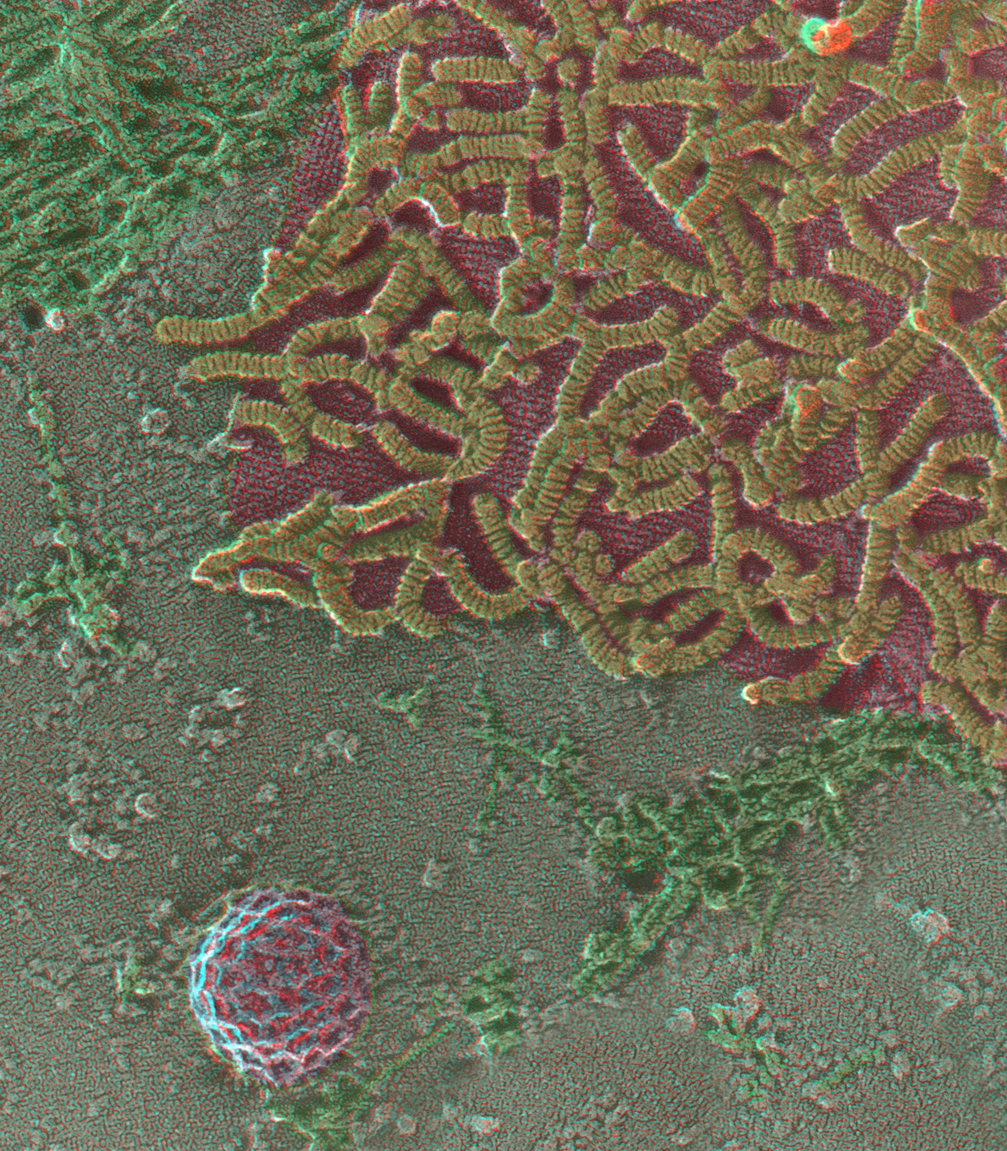
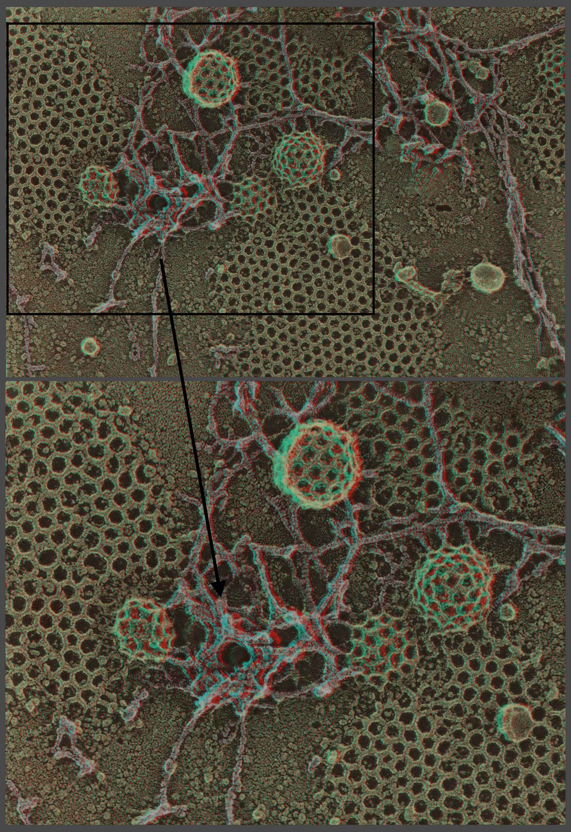
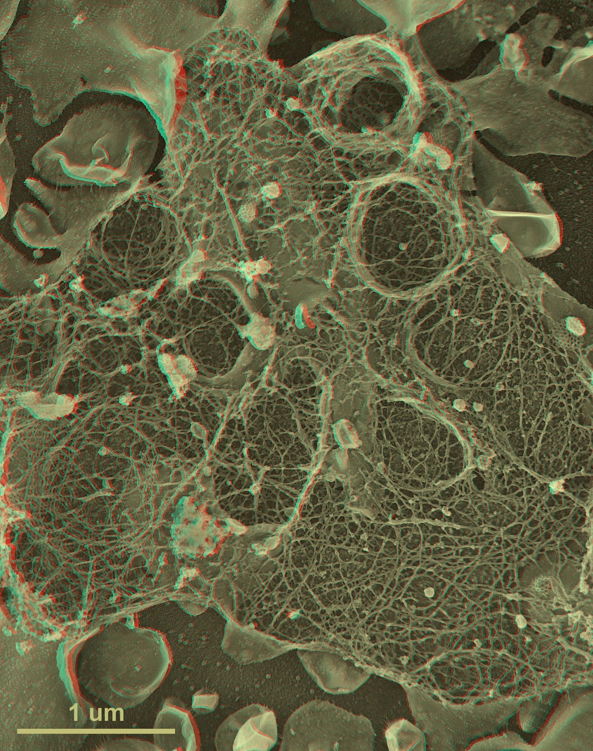
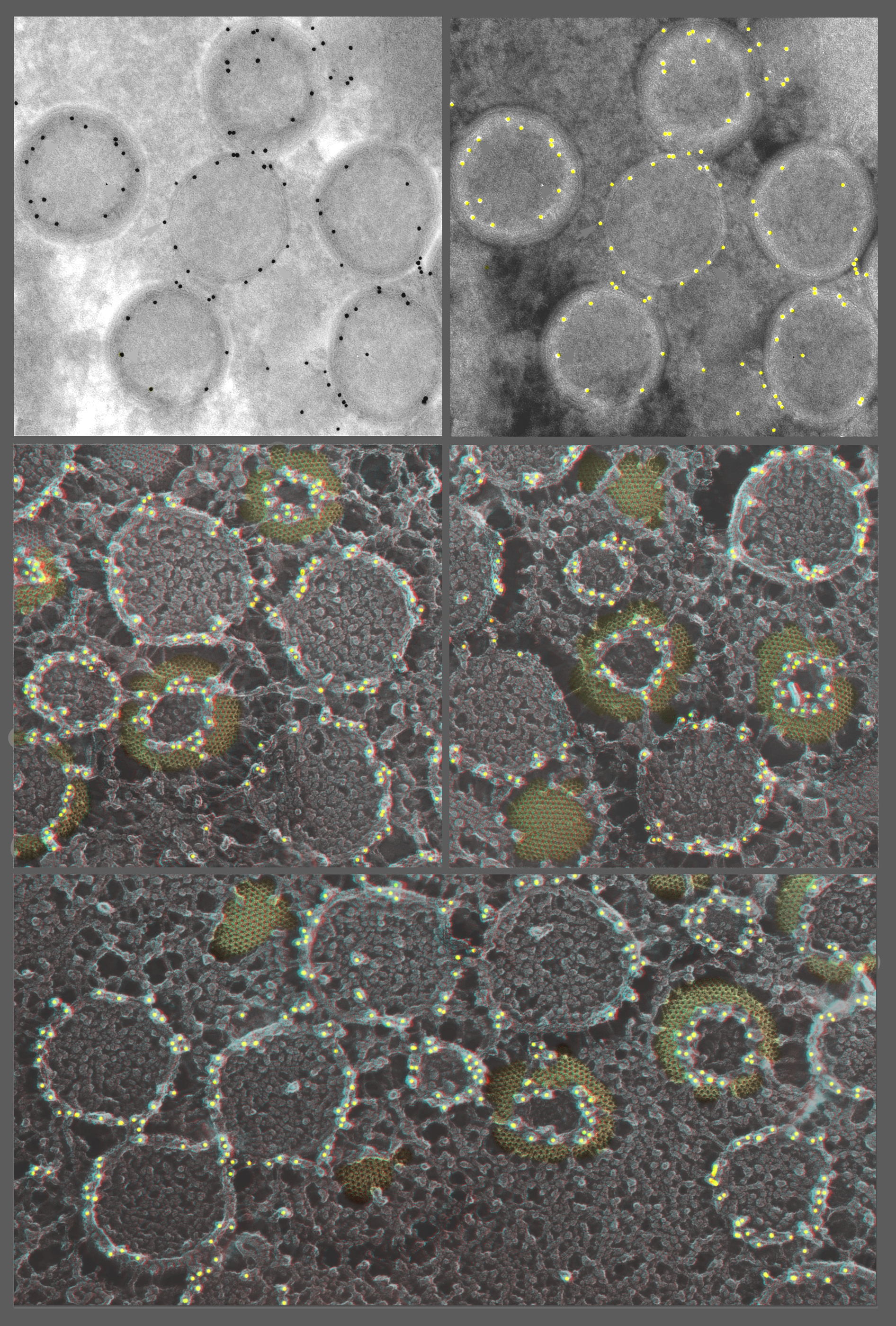