

Abstract
The efficient loading and sustained release of proteins from bioactive microspheres remain a significant challenge. In this study, we have developed bioactive microspheres which can be loaded with protein and then have a controlled rate of protein release into a surrounding medium. This was achieved by preparing a bioactive microsphere system with core-shell structure, combining a calcium silicate (CS) shell with an alginate (A) core by a one-step in situ method. The result was to improve the microspheres' protein adsorption and release, which yielded a highly bioactive material with potential uses in bone repair applications. The composition and the core-shell structure, as well as the formation mechanism of the obtained CS–A microspheres, were investigated by X-ray diffraction, optical microscopy, scanning electron microscopy, energy dispersive spectrometer dot and line-scanning analysis. The protein loading efficiency reached 75 per cent in CS–A microspheres with a core-shell structure by the in situ method. This is significantly higher than that of pure A or CS–A microspheres prepared by non-in situ method, which lack a core-shell structure. CS–A microspheres with a core-shell structure showed a significant decrease in the burst release of proteins, maintaining sustained release profile in phosphate-buffered saline (PBS) at both pH 7.4 and 4.3, compared with the controls. The protein release from CS–A microspheres is predominantly controlled by a Fickian diffusion mechanism. The CS–A microspheres with a core-shell structure were shown to have improved apatite-mineralization in simulated body fluids compared with the controls, most probably owing to the existence of bioactive CS shell on the surface of the microspheres. Our results indicate that the core-shell structure of CS–A microspheres play an important role in enhancing protein delivery and mineralization, which makes these composite materials promising candidates for application in bone tissue regeneration.
Keywords: core-shell structure, calcium silicate, alginate, protein delivery, bioactivity, microspheres
1. Introduction
It is predicted that with increased life expectancy in the developed world, there will be a greater demand for synthetic materials to repair or regenerate lost, injured or diseased bone [1]. There are still few synthetic materials having true bone inductivity, which limits their application for bone regeneration, especially in large-size bone defects. To solve this problem, growth factors, such as bone morphogenetic proteins, have been incorporated into synthetic materials in order to stimulate de novo bone formation in the centre of large-size bone defects. The greatest obstacle with this approach is that the rapid diffusion of the protein from the carrier material, leading to a precipitous loss of bioactivity; the result is often insufficient local induction or failure of bone regeneration [2]. It is critical that the protein is loaded in the carrier material in conditions that maintains its bioactivity [3]. For this reason, the efficient loading and controlled release of a protein from a synthetic material have remained a significant challenge. The use of microspheres as protein–drug carriers has received considerable attention in recent years [4–6]. Compared with macroporous block scaffolds, the chief advantage of microspheres is their superior protein-delivery properties and ability to fill bone defects with irregular and complex shapes and sizes. Upon implantation, the microspheres are easily conformed to the irregular implant site, and the interstices between the particles provide space for both tissue and vascular ingrowth, which are important for effective and functional bone regeneration [7].
Alginates (As) are natural polysaccharides and their production does not have the implicit risk of contamination with allo or xeno-proteins or viruses [8]. Because A is generally cytocompatible, it has been used extensively in medicine, including cell therapy and tissue engineering applications [8–10]. Calcium cross-linked A hydrogel is considered a promising material as a delivery matrix for drugs and proteins, since its gel microspheres form readily in aqueous solutions at room temperature, eliminating the need for harsh organic solvents, thereby maintaining the bioactivity of proteins in the process of loading into the microspheres [11,12]. In addition, calcium cross-linked A hydrogel is degradable under physiological conditions [13,14], which makes A stand out as an attractive candidate material for the protein carrier and bone regeneration [15–17]. However, the major disadvantages of A microspheres is their low loading efficiency and also rapid release of proteins owing to the mesh-like networks of the gel [18]. Previous studies have shown that a core-shell structure in drug–protein carriers can overcome the issues of limited loading efficiencies and rapid release of drug or protein [19–21]. We therefore hypothesized that introducing a core-shell structure into the A microspheres could solve the shortcomings of the pure A.
Calcium silicate (CS) has been tested as a biodegradable biomaterial for bone tissue regeneration. CS is capable of inducing bone-like apatite formation in simulated body fluid (SBF) and its apatite-formation rate in SBF is faster than that of Bioglass and apatite-Wollastonite (A-W) glass-ceramics [22,23]. Titanium alloys plasma-spray coated with CS have excellent in vivo bioactivity [24] and porous CS scaffolds have enhanced in vivo bone formation ability compared with porous β-tricalcium phosphate ceramics [25]. In the light of the many advantages of this material, we decided to prepare CS–A composite microspheres by combining a CS shell with an A core to improve their protein delivery and mineralization for potential protein delivery and bone repair applications.
2. Material and methods
2.1. In situ preparation and characterization of calcium silicate–alginate microspheres with core-shell structure
CS–A microspheres containing 15 and 30 per cent of CS compound (wt%, named as in situ 15CS–A and in situ 30CS–A, respectively), were prepared using an in situ synthesis method by a combination of A cross-linking with Ca2+ ions by the chemical reaction of  and Ca2+ ions. In a typical preparation of in situ 30CS–A microspheres, 0.16 g of Na2SiO3 (Sigma-Aldrich) was dissolved in 25 ml of ddH2O to obtain
  -containing slurry, into which 0.5 g of sodium A (ISP, Koln, Germany) was dissolved. This
  -containing A mixture was extruded drop-wise with a 0.65 mm diameter needle into a 0.1 M CaCl2 cross-linking solution to form CS–A composite spherical particles. The microspheres were reacted with different time by immersing in the cross-linking solution, then filtered, washed with ddH2O twice and dried at 50°C overnight to obtain the in situ 30CS–A composite microspheres with a core (A)-shell (CS compound) structure. In situ 15CS–A microspheres were prepared in a similar way, but by adding 0.08 g of Na2SiO3.
The surface morphology, inner microstructure and element composition/distribution of the microspheres were characterized by optical microscopy (Stemi 2000-C, Zeiss), scanning electron microscopy (SEM) and energy dispersive spectroscopy (EDS) (Jeol JSM6510). The phase composition was characterized by X-ray diffraction (XRD). To evaluate the stability of the CS shells surrounding the A core, the microspheres were subjected to ultrasonic treatment for 1 h in ddH2O. The surface morphology of microspheres after ultrasonic treatment was characterized by SEM. Nanoporosity and pore distribution of microspheres were tested by Brunauer–Emmett–Teller and Barret–Joyner–Halenda analyses through N2 adsorption–desorption isotherms. The open-pore porosity (P) of the microspheres was tested by Archimedes' principle. Ethanol was used as liquid medium. The P was calculated according to the following formulation:
where W1 is the dry weight of the microspheres, W2 is the weight of ethanol saturated with ethanol and W3 is the weight of microspheres suspended in ethanol.
2.2. Non-in situ preparation and characterization of calcium silicate–alginate microspheres
Non-in situ CS–A microspheres, containing 15 and 30 per cent of CS compound (wt%, named as non-in situ 15CS–A and non-in situ 30CS–A, respectively) were prepared as controls. In this study, ‘in situ’ means that we prepared the A–CS microspheres in a one-step reaction as shown in §2.1. ‘Non-in situ’ means that A–CS microspheres were prepared in two steps (the first step is to prepare the CS powders and the second step is then to incorporate CS into A). Non-calcined CS powders were first prepared by a precipitation method according to a previous publication [26]. Half a gram of sodium alginate was dissolved into 25 ml of ddH2O, and then either 0.075 or 0.15 g of CS powders was added to the A solution under stirring for 30 min to create a uniform mixture. The CS–A mixtures were extruded drop-wise with a 0.65 mm diameter needle into a 0.1 M CaCl2 cross-linking solution to form CS–A composite spherical particles. These particles were characterized by the same procedure as described in §2.1 above.
Another control material, pure A microspheres, was prepared by same method, but without the addition of CS or sodium silicate.
2.3. Preparation of bovine serum albumin loaded in situ calcium silicate–alginate, non-in situ calcium silicate–alginate and pure alginate microspheres and evaluation of the loading efficiency of bovine serum albumin in microspheres
First, 25 mg of bovine serum albumin (BSA) was dissolved in 12.5 ml of ddH2O. (i) To prepare BSA loaded in situ CS–A microsphere, BSA solution was added to the  -containing A mixtures (prepared in §2.1 described above) under stirring for 5 min. BSA and
  -containing A mixtures were obtained. The remaining preparation procedures were the same as those described in §2.1 above. The details of the procedures are shown in Scheme 1 (schematic illustration). (ii) To prepare BSA loaded non-in situ CS–A microsphere, BSA solution was added to the CS–A mixtures (prepared in §2.2 described above) under stirring for 5 min. BSA- and CS-containing A mixtures were obtained. The remaining preparation procedures were the same as that described in §2.2 described above. (iii) BSA loaded pure A microspheres were prepared without the addition CS or sodium silicate, by same the method.
Scheme 1.

Schematic illustration for the preparation of bovine serum albumin (BSA) loaded in situ CS–A microspheres with a core-shell structure. Core: alginate; shell: calcium silicate layer. (Online version in colour.)
To evaluate the loading efficiency of BSA in the different microsphere species, both the cross-linking CaCl2 solution from the filtering step and the water from washing step were collected. The residual BSA (RBSA) in the CaCl2 solution and water was measured photometrically (UV min-1240, Shimadzu, Japan) at the wavelength of 280 nm [27]. The loading efficiency of BSA (LE%) was calculated by the equation,
in which TBSA was the total weight of BSA added to the microspheres (25 mg in this study).
2.4. Bovine serum albumin release kinetics from microspheres in phosphate-buffered saline
To evaluate the release kinetics of BSA from the in situ CS–A microspheres, 0.2 g of BSA-loaded in situ CS–A microspheres were placed in 4 ml PBS (pH 7.4) at 37°C for 3, 9, 24, 48, 96, 168 and 336 h. At each time point, 2 ml PBS solution was taken off and replaced with 2 ml of fresh PBS. The amount of BSA released in the PBS was then assessed UV spectroscopy at 280 nm. The released protein at each time point was calculated by deducting the remaining protein in the last time point. The release kinetics of BSA was calculated by the ratio of the released BSA with the total BSA contents in microspheres. Three samples from each microsphere species were taken for mean and standard deviation calculations. The release kinetics of BSA from non-in situ CS–A and pure A microspheres controls were evaluated by the same procedure.
The effect of a lower pH of the PBS on the release kinetics of BSA from microspheres was also evaluated by assessing the BSA release in PBS with a pH 4.3.
2.5. The in vitro apatite-mineralization ability of the in situ calcium silicate–alginate microspheres in acellular simulated body fluid
A short-term in vitro bioactivity study was carried out using acellular SBF [28,29], which has an ion concentration similar to human blood plasma. Briefly, AR-grade CaCl2, K2HPO4·3H2O, NaCl, KCl, MgCl2·6H2O, NaHCO3 and Na2SO4 were dissolved in distilled water and the pH adjusted to 7.4 with HCl and tris base. Three hundred milligrams of microspheres were immersed in 200 ml of SBF, and kept at 37°C for 3 days, after which they were washed by water for two times and dried at 60°C for 1 day. The samples were analysed by SEM and EDS to determine their apatite-mineralization abilities. The apatite-mineralization ability of the non-in situ CS–A and pure A microspheres controls were evaluated by the same procedure. The concentrations of  , Ca2+ and
  ions in SBF after soaking were tested by atomic emission spectroscopy (AES, Perkin-Elmer Optima 7000DV).
2.6. Statistical analysis
The data were expressed as means ± standard deviation (s.d.) for all experiments and were analysed using one-way ANOVA with a post hoc test. A p-value < 0.05 was considered statistically significant.
3. Results and discussion
3.1. Characterization of the in situ calcium silicate–alginate microspheres with core-shell structure
An in situ method was used to prepare CS–A microspheres with a core-shell structure at room temperature. Optical microscopy images show that the microspheres thus obtained were encrusted by a white CS layer (figure 1b,c) and approximately 1 mm across (see the electronic supplementary material, figure S1). On the non-in situ produced 30CS–A microspheres only a limited number of white CS particles were seen on the surface (figure 1e), whereas no obvious CS particles could be found on the pure A microspheres (figure 1a). High magnification SEM shows the surface microstructure of the CS–A microspheres. The in situ produced 15CS and 30CS–A microspheres have a coarse surface owing to the formation of a shell composed of CS particles (figure 2b,c), whereas, by comparison, the pure A (figure 2a), non-in situ 15CS–A (figure 2d) and non-in situ 30CS–A (figure 2e) have a smoother surface. EDS analysis revealed the presence of Ca and Si elements in both in situ 30CS–A (figure 2c) and non-in situ 30CS–A (figure 2e) microspheres. XRD analysis indicates that the main phase of CS in the in situ 30CS–A and non-in situ 30CS–A microspheres is Ca5Si6O16(OH)2 (figure 2f). The microstructure and composition of the cross section of microspheres were characterized by SEM and EDS line scanning analysis (figure 3). The in situ CS–A microspheres had an obvious core-shell structure (figure 3b,c), which was not seen in the pure A and non-in situ CS–A microspheres (figure 3a,d,e). EDS line scanning analysis for the inner element distribution of the in situ 30CS–A microspheres indicates that Ca and Si elements were found mainly in the shell of microspheres; little or no Ca and Si elements were found in the core of microspheres (figure 3f), which further confirmed that the CS (shell) wrap the A microspheres (core), forming the core-shell structure of the in situ CS–A microspheres. N2 adsorption–desorption analysis has shown that there are few nanopores in the microspheres. However, the open P of A microspheres is only 14.3 per cent, and in situ 30CS–A microspheres reacted with CaCl2 for 30 and 120 min and have 22.8 and 25 per cent P, respectively, which indicates that CS shells improve the P of microspheres.
Figure 1.

Optical microscopy images for (a) the pure A, (b) in situ 15CS–A, (c) in situ 30CS–A, (d) non-in situ 15CS–A and (e) non-in situ 30CS–A microspheres. (b,c) In situ CS–A microspheres appear white because of a silicate layer, as a shell, on the surface of A (core). (e) Only a few white particles on the surface of non-in situ CS–A microspheres. (Online version in colour.)
Figure 2.

SEM images for the surface of (a) pure A, (b) in situ 15CS–A, (c) in situ 30CS–A, (d) non-in situ 15CS–A and (e) non-in situ 30CS–A microspheres; (f) XRD pattern for the obtained microspheres. Silicate particles mainly composed of Ca5Si6O16(OH)2 phase were formed on the surface of (b) in situ 15CS–A and (c) in situ 30CS–A microspheres; however, (d) pure A, non-in situ 15CS–A, and (e) non-in situ 30CS–A showed a more smooth surface, compared with in situ CS–A microspheres. (f) XRD shows main Ca5Si6O16(OH)2 phase in the in situ 30CS–A and non-in situ 30CS–A microspheres. (c) EDS shows the Ca and Si elements in the in situ 30CS–A and (e) non-in situ 30CS–A microspheres. (a) The ratio of Ca–Si in the in situ 30CS–A and non-in situ 30CS–A microspheres was 20.3 and 33.2, respectively. No Si element was detected in pure A microspheres. (Online version in colour.)
Figure 3.

SEM images for the cross sections of (a) pure A, (b) in situ 15CS–A, (c) in situ 30CS–A, (d) non-in situ 15CS–A and (e) non-in situ 30CS–A microspheres. (b,c) In situ CS–A microspheres have a clear core-shell structure. (f) EDS line scanning analysis (through black line) for the inner element distribution of in situ 30CS–A microspheres. Ca and Si elements are mainly in the shell of microspheres. There are no obvious Ca and Si elements in the core of microspheres. (Online version in colour.)
We have tested the stability of the CS shell by an ultrasonic shaking method described previously [30]. After 1 h of ultrasonic treatment, the CS shell was still present on the surface of the in situ 30CS–A microspheres and showed no evidence of delaminating from the microspheres (see the electronic supplementary material, figure S2), indicative of a high degree of stability.
The large size of the microspheres will provide not only a sufficient surface area for bone cell attachment and growth, but also large interstitial space (room) between the microspheres for both tissue and vascular ingrowth, which is an essential requirement for effective and functional bone regeneration [31,32]. The core-shell structure of the microspheres has potential applications for drug and protein delivery by a sustained release, and the shell provides the bioactive substrate necessary for potential bone tissue regeneration by virtue of the inherent bioactivity of the CS [21].
3.2. The formation mechanism of the in situ calcium silicate–alginate microspheres with core-shell structure
We have investigated the mechanism for the formation of core-shell structure by observing the surface and cross-section morphology of the microspheres over different reaction times as shown in figure 4. It is observed that all the A microspheres prepared by the in situ preparation method are completely covered with the silicate lays at different reaction times of (figure 4a–c) 30, (figure 4d–f) 60 and (figure 4g–i) 120 min. It is interesting to note that silicate layers on the surface of CS–A microspheres reacted for 30 and 60 min are composed of finer particles (figure 4c,f), compared with those reacted for 120 min with larger particles (figure 4i). Therefore, this indicated that the reaction time is not the key factor to form the core-shell structure, but the important factor to improve the crystal growth of CS. The potential mechanism for the formation of the core-shell structure is suggested. In our study, Na2SiO3 and A were dissolved together to form a uniform Si-containing A solution. When this solution is dropped into CaCl2 solution, A will cross-link with Ca2+ ions to produce Ca–A and form microspheres. At the same time, the  will very quickly diffuse onto the surface of the microspheres and react with the Ca2+ to form a CS shell. With increased reaction time, more and more Ca2+ and
  will be involved in the chemistry reaction, which will further stimulate the crystal growth of CS. Therefore, the particle size of CS will increase with the increase of reacting time.
Figure 4.

SEM images for the in situ 30CS–A microspheres prepared using different reaction times in cross-section solution of CaCl2. (a,b,c) for 30 min, (d,e,f) for 60 min and (g,h,i) for 120 min.
3.3. Advanced protein-delivery ability and pH effect on protein release for the in situ calcium silicate–alginate microspheres with core-shell structure
3.3.1. Protein loading and delivery
BSA was selected as the model protein as it is a stable molecule and also relatively inexpensive. In the human circulatory system, serum protein albumin is by far the most abundant protein, accounting for 60 per cent of the total serum protein. BSA is commonly used to simulate human albumin, owing to the structural homology of the two proteins [33]. We loaded BSA into the in situ CS–A, non-in situ CS–A and pure A microspheres at room temperature, in the process of preparing the microspheres. The BSA did not affect the core-shell structure of the in situ CS–A microspheres (see the electronic supplementary material, figure S3). The loading efficiency of BSA in the in situ 15CS and 30CS–A microspheres reached 53 and 75 per cent, respectively, significantly higher than that of the non-in situ 15CS–A at 25 per cent, non-in situ 30CS–A at 37 per cent and pure A microspheres at 21 per cent (figure 5a). The rate of BSA release from the in situ CS–A microspheres was significantly slower than that of the non-in situ CS–A and pure A microspheres (figure 5b). These results indicate that in situ CS–A microspheres not only enhance the loading efficiency of BSA, but also decrease the burst release of BSA and maintain a more sustained release, compared with non-in situ CS–A and pure microspheres (see figure 7, showing a schematic illustration of BSA release from the three microsphere types). Alginate microspheres have obvious advantages for protein delivery and bone repair because of their preparation conditions, degradability and compatibility, but their main drawback is the relatively low loading efficiency and quick release for drug/protein stemming from large gel P [18]. In this study, we have overcome these disadvantages with the core-shell structure, which combines CS with A. As we prepared BSA-containing A and CS–A microspheres in CaCl2 cross-linking solution, parts of BSA will be released into CaCl2 solution through the network structure of A. However, the formed CS may block the network pore structure of A and further inhibit BSA release into CaCl2 solution, which leads to an improved loading efficiency. The inner core of A provides sufficient space to increase BSA loading and the outer shell CS layer prevents BSA leakage, thereby enhancing the loading efficiency of BSA upwards of 75 per cent. This property is very important, given the high cost of the majority of growth factors and drugs, and the improved loading efficiency will in itself greatly reduce the proportion of costs associated with growth factors and drugs. We believe there are two major factors contributing to the slower rate of release of BSA with in situ CS–A microspheres. One factor is the CS shell on the surface of microspheres which appears to inhibit the BSA release from the microsphere. The other factor is that CS has the ability to induce the formation of nano-size apatite in biological solution (PBS or SBF; see in figure 8), and these nano-size apatite particles may bind proteins by the chemical side groups OH−,  and
and  , thereby slowing BSA release from microspheres [34,35]. Our recent study has further confirmed that the forme apatite plays an important role in improving protein delivery [27].
Figure 5.

(a) The loading efficiency of protein (BSA) in the microspheres. In situ CS–A microspheres have higher loading efficiency than pure A and non-in situ CS–A microspheres. With the increase of CS contents in A microspheres, the loading efficiency improved. (b) Protein (BSA) release kinetics from microspheres in PBS with a pH 7.4 and (c) the linear relationship of release and square root time (h1/2). (b) Shows the in situ CS–A microspheres with core-shell structure have a slower BSA release than pure A and non-in situ CS–A microspheres. The linear relationship of release and square root time in figure (c) indicates the diffusing mechanism of protein release from microspheres. (Online version in colour.)
Figure 7.
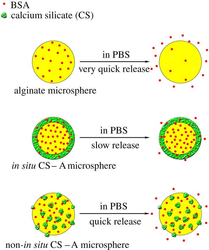
Schematic illustration of the release of BSA from pure A, in situ CS–A and non-in situ CS–A microspheres. In situ CS–A microspheres with core-shell structure have a slow release of BSA; however, pure A and non-in situ CS–A microspheres have quick release of BSA. (Online version in colour.)
Figure 8.

SEM micrographs and EDS analysis for the microspheres before and after soaking in SBFs for 3 days. Alginate microspheres (a) before and (b) after soaking, in situ 30CS–A microspheres (c) before and (d) after soaking, non-in situ 30CS–A microspheres (e) before and (f) after soaking. (b) No apatite particles formed on pure A microspheres after soaking in SBF. (d) Apatite layer composed of lath-like particles formed on the surface of in situ 30CS–A microspheres. (f) There are a few apatite particles on the surface of non-in situ 30CS–A microspheres. (f) EDS analysis shows that P peaks were very obvious for in situ 30CS–A microspheres in SBF and the ratio of Ca–P of apatite is 1.82. There is a weak P peak for non-in situ 30CS–A microspheres in SBF and the ratio of Ca–P of apatite is 23.9.
Our experiments showed that there is a linear relationship between the amount of BSA released from the microspheres over the square root of time (figure 5c), indicating that BSA release from the microspheres is mainly controlled by a Fickian diffusion mechanism according to the Higuchi model (Q = kHt1/2, where Q is the amount of drug released in time t and kH is the Higuchi dissolution constant) [36,37].
3.3.2. The effect of pH on protein release
Previous studies have shown that the area immediately surrounding the ruffled border of osteoclasts during bone remodelling has a pH of approximately 4.0—the homeostatic body fluid is approximately pH 7.4 [38,39]. Other studies have shown that the local environment in the initial fracture haematoma is acidic, which later becomes neutral as healing progresses, and then becomes alkaline, a process that helps support differentiation-related events during fracture healing [40]. In the present study, in order to evaluate the effect of pH, BSA release from microspheres was carried out in PBS buffer with pH 7.4 and 4.3 to simulate the local pH environment in bone. Our results showed that pH has no obvious effect on BSA release from the in situ 30CS–A microspheres, which maintained a stable and sustained release that was significantly slower than that of the other microspheres (figure 6). At pH 4.3 non-in situ 30CS–A microspheres had a faster release rate than that at pH 7.4 (figure 5); this is most likely attributable to the faster rate of dissolution of CS particles at pH 4.3, which therefore accelerates the release rate of BSA. The existence of a CS shell on the surface of the in situ 30CS–A microspheres appears to obviate the effect of low pH on BSA release from these microspheres. Our results indicate that in both acidic and neutral environments in situ CS–A microspheres still maintain a very slow and sustained release of protein owing to the core-shell structure. The slow release of protein from in situ CS–A microspheres is their main advantage, compared with non-in situ CS–A and pure A microspheres.
Figure 6.

The effect of pH of PBS on protein (BSA) release from microspheres. pH has no obvious effect on protein release from in situ 30CS–A microspheres; however, non-in situ 30CS–A microspheres have a quicker protein release at pH 4.3 than at pH 7.4. (Online version in colour.)
3.4. The in vitro mineralization of the in situ calcium silicate–alginate microspheres with core-shell structure
The other aim of this study was to prepare bioactive CS–A composite microspheres for potential bone repair applications. CS compounds have been shown to be highly bioactive for bone tissue regeneration owing to these materials' excellent osteogenic properties in vivo and apatite-mineralization ability in SBF [23,25]. Traditionally, bioactive inorganic materials, including CS, hydroxyapatite and β-tricalcium phosphate powders have been incorporated into polymer material by a non-in situ method [41–43]. Since the majority of the bioactive compounds end up encased within the centre of the polymer matrix by this method, the resulting mineralization of the composite materials is far from optimal. In our study, we used an in situ preparation method to incorporate bioactive CS onto the surface of A thereby forming a bioactive CS shell, which significantly enhanced the apatite-mineralization ability in SBF. On pure A microspheres, no apatite particles formed after 3 days of soaking in SBF (figure 8b). On the in situ 30CS–A microspheres, however, an apatite layer composed of lath-like particles had formed on the surface (figure 8d); a limited number of apatite particles had formed on the surface of non-in situ 30CS–A microspheres (figure 8f). EDS analysis showed that the P signal in in situ 30CS–A microspheres was stronger than that in non-in situ 30CS–A microspheres. The concentrations of Ca2+ and  ions in SBF from the in situ 30CS microspheres were lower than in SBF from the other microspheres species (table 1), suggesting that more Ca2+ and
  ions are used in the apatite formation on the surface of the in situ 30CS microspheres than is the case of the other microspheres. These results indicate that in situ 30CS–A microspheres have better apatite-mineralization ability compared with pure A and non-in situ CS–A microspheres. Apatite-mineralization ability of bioactive material is widely used as an indicator of bioactivity since some bioactive materials form a bond with host bone via an apatite layer [28]. It therefore stands to reason that the superior apatite-mineralization of the in situ CS–A microspheres may indeed be one of the factors most contributing to the potential bone repair applications of this material.
Table 1.
The concentrations of  , Ca2+ and
  ions (ppm) in SBFs after soaking the microspheres.
| ion concentration (ppm) |
|||
|---|---|---|---|
| microsphere type |  |
Ca2+ |  |
| alginate | 0 | 277.0 | 12.76 |
| in situ 30CS–A | 11.49 | 263.5 | 11.06 |
| non-in situ 30CS–A | 4.15 | 283.7 | 12.38 |
4. Conclusions
In summary, CS–A microspheres with a core-shell structure were successfully prepared by a one-step in situ method. The microspheres were composed of a CS shell and an A core. These microspheres were demonstrated to be effective protein carriers, having a capacity for high protein loads and subsequent sustained release. The microspheres had excellent apatite-mineralization ability. CS–A microspheres with a core-shell structure represent a promising candidate biomaterial for bone repair/regeneration by being both a flexible filler material and growth factor/drug carrier.
Acknowledgements
Funding for this study was provided by a research grant from the Alexander von Humboldt Foundation (C.W.) and the South Korean Ministry of Education, Science and Technology Programme, Project WCU ITCE no. R31-2008-000-10100-0 (G.C.).
References
- 1.Hench L. L., Thompson I. 2010. Twenty-first century challenges for biomaterials. J. R. Soc. Interface 7(Suppl. 4), S379–S391 10.1098/rsif.2010.0151.focus (doi:10.1098/rsif.2010.0151.focus) [DOI] [PMC free article] [PubMed] [Google Scholar]
- 2.Wei G., Jin Q., Giannobile W. V., Ma P. X. 2007. The enhancement of osteogenesis by nano-fibrous scaffolds incorporating rhBMP-7 nanospheres. Biomaterials 28, 2087–2096 10.1016/j.biomaterials.2006.12.028 (doi:10.1016/j.biomaterials.2006.12.028) [DOI] [PMC free article] [PubMed] [Google Scholar]
- 3.van de Manakker F., Braeckmans K., el Morabit N., De Smedt S. C., van Nostrum C. F., Hennink W. E. 2009. Protein-release behavior of self-assembled PEG-beta-cyclodextrin/PEG-cholesterol hydrogels. Adv. Func. Mater. 19, 2992–3001 10.1002/adfm.200900603 (doi:10.1002/adfm.200900603) [DOI] [Google Scholar]
- 4.Lee K., Silva E. A., Mooney D. J. 2010. Growth factor delivery-based tissue engineering: general approaches and a review of recent developments. J. R. Soc. Interface 8, 153–170 10.1098/rsif.2010.0223 (doi:10.1098/rsif.2010.0223) [DOI] [PMC free article] [PubMed] [Google Scholar]
- 5.Pareta R., Edirisinghe M. J. 2006. A novel method for the preparation of biodegradable microspheres for protein drug delivery. J. R. Soc. Interface 3, 573–582 10.1098/rsif.2006.0120 (doi:10.1098/rsif.2006.0120) [DOI] [PMC free article] [PubMed] [Google Scholar]
- 6.Wu C., Zreiqat H. 2010. Porous bioactive diopside (CaMgSi(2)O(6)) ceramic microspheres for drug delivery. Acta Biomater. 6, 820–829 10.1016/j.actbio.2009.09.025 (doi:10.1016/j.actbio.2009.09.025) [DOI] [PubMed] [Google Scholar]
- 7.Hsu F. Y., Chueh S. C., Wang Y. J. 1999. Microspheres of hydroxyapatite/reconstituted collagen as supports for osteoblast cell growth. Biomaterials 20, 1931–1936 10.1016/S0142-9612(99)00095-2 (doi:10.1016/S0142-9612(99)00095-2) [DOI] [PubMed] [Google Scholar]
- 8.Xie M., Olderoy M. O., Andreassen J. P., Selbach S. M., Strand B. L., Sikorski P. 2010. Alginate-controlled formation of nanoscale calcium carbonate and hydroxyapatite mineral phase within hydrogel networks. Acta Biomater. 6, 3665–3675 10.1016/j.actbio.2010.03.034 (doi:10.1016/j.actbio.2010.03.034) [DOI] [PubMed] [Google Scholar]
- 9.Tampieri A., Sandri M., Landi E., Celotti G., Roveri N., Mattioli-Belmonte M., Virgili L., Gabbanelli F., Biagini G. 2005. HA/alginate hybrid composites prepared through bio-inspired nucleation. Acta Biomater. 1, 343–351 10.1016/j.actbio.2005.01.001 (doi:10.1016/j.actbio.2005.01.001) [DOI] [PubMed] [Google Scholar]
- 10.Xu S. W., Lu Y., Li J., Zhang Y. F., Jiang Z. Y. 2007. Preparation of novel silica-coated alginate gel beads for efficient encapsulation of yeast alcohol dehydrogenase. J. Biomater. Sci. Polym. Ed. 18, 71–80 10.1163/156856207779146141 (doi:10.1163/156856207779146141) [DOI] [PubMed] [Google Scholar]
- 11.Jay S. M., Saltzman W. M. 2009. Controlled delivery of VEGF via modulation of alginate microparticle ionic crosslinking. J. Control Release 134, 26–34 10.1016/j.jconrel.2008.10.019 (doi:10.1016/j.jconrel.2008.10.019) [DOI] [PMC free article] [PubMed] [Google Scholar]
- 12.Kikuchi A., Kawabuchi M., Watanabe A., Sugihara M., Sakurai Y., Okano T. 1999. Effect of Ca2+-alginate gel dissolution on release of dextran with different molecular weights. J. Control Release 58, 21–28 10.1016/S0168-3659(98)00141-2 (doi:10.1016/S0168-3659(98)00141-2) [DOI] [PubMed] [Google Scholar]
- 13.Kibat P. G., Igari Y., Wheatley M. A., Eisen H. N., Langer R. 1990. Enzymatically activated microencapsulated liposomes can provide pulsatile drug release. FASEB J. 4, 2533–2539 [DOI] [PubMed] [Google Scholar]
- 14.Park K., Shalaby W. S., Park H. 1993. Biodegradable hydrogels for drug delivery, ch. 5, pp. 99–140 Lancaster, PA: Technomic [Google Scholar]
- 15.Hosoya K., Ohtsuki C., Kawai T., Kamitakahara M., Ogata S., Miyazaki T., Tanihara M. 2004. A novel covalently crosslinked gel of alginate and silane with the ability to form bone-like apatite. J. Biomed. Mater. Res. A 71, 596–601 10.1002/jbm.a.30189 (doi:10.1002/jbm.a.30189) [DOI] [PubMed] [Google Scholar]
- 16.Matsuno T., et al. 2008. Preparation of injectable 3D-formed beta-tricalcium phosphate bead/alginate composite for bone tissue engineering. Dent. Mater. J. 27, 827–834 10.4012/dmj.27.827 (doi:10.4012/dmj.27.827) [DOI] [PubMed] [Google Scholar]
- 17.Turco G., Marsich E., Bellomo F., Semeraro S., Donati I., Brun F., Grandolfo M., Accardo A., Paoletti S. 2009. Alginate/hydroxyapatite biocomposite for bone ingrowth: a trabecular structure with high and isotropic connectivity. Biomacromolecules 10, 1575–1583 10.1021/bm900154b (doi:10.1021/bm900154b) [DOI] [PubMed] [Google Scholar]
- 18.Halder A., Mukherjee S., Sa B. 2005. Development and evaluation of polyethyleneimine-treated calcium alginate beads for sustained release of diltiazem. J. Microencapsul. 22, 67–80 10.1080/02652040500045003 (doi:10.1080/02652040500045003) [DOI] [PubMed] [Google Scholar]
- 19.Chang M. W., Stride E., Edirisinghe M. 2010. Stimulus-responsive liquids for encapsulation storage and controlled release of drugs from nano-shell capsules. J. R. Soc. Interface 8, 451–456 10.1098/rsif.2010.0428 (doi:10.1098/rsif.2010.0428) [DOI] [PMC free article] [PubMed] [Google Scholar]
- 20.Molvinger K., Quignard F., Brunel D., Boissiere M., Devoisselle J. M. 2004. Porous chitosan-silica hybrid microspheres as a potential catalyst. Chem. Mater. 16, 3367–3372 10.1021/cm0353299 (doi:10.1021/cm0353299) [DOI] [Google Scholar]
- 21.Soppimath K. S., Liu L. H., Seow W. Y., Liu S. Q., Powell R., Chan P., Yang Y. Y. 2007. Multifunctional core/shell nanoparticles self-assembled from pH-induced thermosensitive polymers for targeted intracellular anticancer drug delivery. Adv. Func. Mater. 17, 355–362 10.1002/adfm.200500611 (doi:10.1002/adfm.200500611) [DOI] [Google Scholar]
- 22.De Aza P. N., Luklinska Z. B., Martinez A., Anseau M. R., Guitian F., De Aza S. 2000. Morphological and structural study of pseudowollastonite implants in bone. J. Microsc. 197, 60–67 10.1046/j.1365-2818.2000.00647.x (doi:10.1046/j.1365-2818.2000.00647.x) [DOI] [PubMed] [Google Scholar]
- 23.Siriphannon P., Kameshima Y., Yasumori A., Okada K., Hayashi S. 2002. Formation of hydroxyapatite on CaSiO3 powders in simulated body fluid. J. Euro Ceram. Soc. 22, 511–520 10.1016/S0955-2219(01)00301-6 (doi:10.1016/S0955-2219(01)00301-6) [DOI] [Google Scholar]
- 24.Xue W., Liu X., Zheng X., Ding C. 2005. In vivo evaluation of plasma-sprayed wollastonite coating. Biomaterials 26, 3455–3460 10.1016/j.biomaterials.2004.09.027 (doi:10.1016/j.biomaterials.2004.09.027) [DOI] [PubMed] [Google Scholar]
- 25.Xu S., Lin K., Wang Z., Chang J., Wang L., Lu J., Ning C. 2008. Reconstruction of calvarial defect of rabbits using porous calcium silicate bioactive ceramics. Biomaterials 29, 2588–2596 10.1016/j.biomaterials.2008.03.013 (doi:10.1016/j.biomaterials.2008.03.013) [DOI] [PubMed] [Google Scholar]
- 26.Ni S., Chang J., Chou L. 2006. A novel bioactive porous CaSiO3 scaffold for bone tissue engineering. J. Biomed. Mater. Res. A 76, 196–205 [DOI] [PubMed] [Google Scholar]
- 27.Wu C., Zhang Y., Ke X., Xie Y., Zhu H., Crawford R., Xiao Y. 2010. Bioactive mesopore-glass microspheres with controllable protein-delivery properties by biomimetic surface modification. J. Biomed. Mater. Res. A 95, 476–485 [DOI] [PubMed] [Google Scholar]
- 28.Kokubo T., Takadama H. 2006. How useful is SBF in predicting in vivo bone bioactivity? Biomaterials 27, 2907–2915 10.1016/j.biomaterials.2006.01.017 (doi:10.1016/j.biomaterials.2006.01.017) [DOI] [PubMed] [Google Scholar]
- 29.Wu C., Ramaswamy Y., Zhu Y., Zheng R., Appleyard R., Howard A., Zreiqat H. 2009. The effect of mesoporous bioactive glass on the physiochemical, biological and drug-release properties of poly(DL-lactide-co-glycolide) films. Biomaterials 30, 2199–2208 10.1016/j.biomaterials.2009.01.029 (doi:10.1016/j.biomaterials.2009.01.029) [DOI] [PubMed] [Google Scholar]
- 30.Ryu J., Ku S. H., Lee H., Park C. B. 2010. Mussel-inspired polydopamine coating as a universal route to hydroxyapatite crystallization. Adv. Func. Mater. 20, 2132–2139 10.1002/adfm.200902347 (doi:10.1002/adfm.200902347) [DOI] [Google Scholar]
- 31.Luciani A., Coccoli V., Orsi S., Ambrosio L., Netti P. A. 2008. PCL microspheres based functional scaffolds by bottom-up approach with predefined microstructural properties and release profiles. Biomaterials 29, 4800–4807 10.1016/j.biomaterials.2008.09.007 (doi:10.1016/j.biomaterials.2008.09.007) [DOI] [PubMed] [Google Scholar]
- 32.Malafaya P. B., Santos T. C., van Griensven M., Reis R. L. 2008. Morphology, mechanical characterization and in vivo neo-vascularization of chitosan particle aggregated scaffolds architectures. Biomaterials 29, 3914–3926 10.1016/j.biomaterials.2008.06.023 (doi:10.1016/j.biomaterials.2008.06.023) [DOI] [PubMed] [Google Scholar]
- 33.He X. M., Carter D. 1992. Atomic structure and chemistry of human serum albumin. Nature 358, 209–215 10.1038/358209a0 (doi:10.1038/358209a0) [DOI] [PubMed] [Google Scholar]
- 34.Wassell D. T., Hall R. C., Embery G. 1995. Adsorption of bovine serum albumin onto hydroxyapatite. Biomaterials 16, 697–702 10.1016/0142-9612(95)99697-K (doi:10.1016/0142-9612(95)99697-K) [DOI] [PubMed] [Google Scholar]
- 35.Xia W., Chang J. 2006. Well-ordered mesoporous bioactive glasses (MBG): a promising bioactive drug delivery system. J. Control Release 110, 522–530 10.1016/j.jconrel.2005.11.002 (doi:10.1016/j.jconrel.2005.11.002) [DOI] [PubMed] [Google Scholar]
- 36.Higuchi T. 1963. Mechanism of sustained-action medication. Theoretical analysis of rate of release of solid drugs dispersed in solid matrices. J. Pharm. Sci. 52, 1145–1149 10.1002/jps.2600521210 (doi:10.1002/jps.2600521210) [DOI] [PubMed] [Google Scholar]
- 37.Zhu Y. F., Kaskel S. 2009. Comparison of the in vitro bioactivity and drug release property of mesoporous bioactive glasses (MBGs) and bioactive glasses (BGs) scaffolds. Micropor. Mesopor. Mater. 118, 176–182 10.1016/j.micromeso.2008.08.046 (doi:10.1016/j.micromeso.2008.08.046) [DOI] [Google Scholar]
- 38.Baron R. 1989. Molecular mechanism of bone resolution by osteoclast. Anat. Rec. 224, 317–324 10.1002/ar.1092240220 (doi:10.1002/ar.1092240220) [DOI] [PubMed] [Google Scholar]
- 39.Baron R., Neff L., Louvard D., Courtoy P. 1985. Cell-mediated extracellular acidification and bone bone resolution. J. Cell Biol. 101, 2210–2222 10.1083/jcb.101.6.2210 (doi:10.1083/jcb.101.6.2210) [DOI] [PMC free article] [PubMed] [Google Scholar]
- 40.Hollinger J., Wong M. 1996. The integrated process of hard tissue regeneration with special emphasis on fracture healing. Oral Surg. Oral Med. Oral Pathol. Oral Radiol. Endod. 82, 594–606 10.1016/S1079-2104(96)80431-8 (doi:10.1016/S1079-2104(96)80431-8) [DOI] [PubMed] [Google Scholar]
- 41.Bi L., Cheng W., Fan H., Pei G. 2010. Reconstruction of goat tibial defects using an injectable tricalcium phosphate/chitosan in combination with autologous platelet-rich plasma. Biomaterials 31, 3201–3211 10.1016/j.biomaterials.2010.01.038 (doi:10.1016/j.biomaterials.2010.01.038) [DOI] [PubMed] [Google Scholar]
- 42.Li H., Chang J. 2005. Preparation, characterization and in vitro release of gentamicin from PHBV/wollastonite composite microspheres. J. Control Release 107, 463–473 10.1016/j.jconrel.2005.05.019 (doi:10.1016/j.jconrel.2005.05.019) [DOI] [PubMed] [Google Scholar]
- 43.Singh M. K., Shokuhfar T., Gracio J. J. D., de Sousa A. C. M., Fereira J. M. D., Garmestani H., Ahzi S. 2008. Hydroxyapatite modified with carbon-nanotube-reinforced poly(methyl methacrylate): a nanocomposite material for biomedical applications. Adv. Func. Mater. 18, 694–700 10.1002/adfm.200700888 (doi:10.1002/adfm.200700888) [DOI] [Google Scholar]