Abstract
SimSET (a Simulation System for Emission Tomography) is being modified to more accurately simulate typical PET block detector tomographs. A new detector module that models the detector system as a collection of rectangular boxes is being added to the software. The new model is sufficiently general to allow many more imaginative or speculative detector systems to be simulated.
I. Introduction
SimSET (a Simulation System for Emission Tomography) [1] is heavily used by researchers around the world to investigate single photon emission computed tomography (SPECT) and positron emission tomography (PET). However, SimSET’s current model for the detectors of a typical cylindrical PET system is a collection of cylindrical annuli. This leads to an overestimation of sensitivity and other biases in PET simulation that researchers have partially dealt with by modifying SimSET (e.g. [2]) or applying scaling factors (e.g. [3]). Researchers have also needed to modify SimSET, or use other simulation packages, to prototype innovative detector geometries.
This paper describes a new detector model we are currently implementing and testing for the SimSET detector module. Its primary intent is to allow accurate simulation of the most common design of commercial PET systems – cylindrical arrays of block detectors. However, the model will also accommodate many more imaginative PET detector arrays, as well as many SPECT geometries. In its most general form, the model will support any arrangement of right rectangular boxes such that (1) the boxes all lie entirely outside a right-elliptical cylinder that contains the object/phantom, (2) the interiors of the boxes do not overlap, and (3) two faces of every box are perpendicular to the tomograph axis (or, equivalently, parallel to the x-y plane).
II. Detector System Model
A. Current Detector System Models
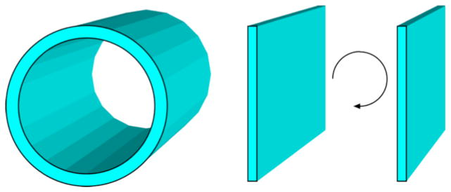
SimSET currently includes two detector system models for PET, one that models the detector as a collection of concentric cylindrical annuli, the other that uses two opposing planar detectors (Fig. 1). Both models allow material variations both axially and radially, but do not allow changes transaxially; the latter model allows the detectors to rotate about the field-of-view.
Fig. 1.
The current release version of SimSET provides two detector models for PET: cylindrical detectors and opposing planar detectors.
B. Block Detector System Model
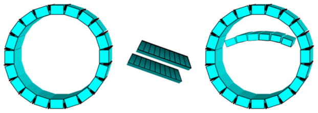
The block detector system model will simulate the detector system as a collection of right rectangular boxes. This model will allow users to simulate typical block-based cylindrical tomographs, pixilated positron emission mammography (PEM) detectors, and many more imaginative tomograph designs (Fig. 2).
Fig. 2.
The new block detector model will allow for realistic modeling of block-based cylindrical PET systems, pixelated PEM modules, and more unusual designs such as tomographs with inserts.
A block detector system will be specified in three steps: first the block design(s) will be specified; then a ring will be defined as a collection of blocks; finally, the detector system is defined as a collection of rings.
A block is a right rectangular box that can be subdivided into layers and, within the layers, elements. Both the layers and elements are also right rectangular boxes with faces parallel to those of the detector (Fig. 3). The layers and elements completely fill the volume of the block. The user specifies a material for each element and whether that element is active (e.g., scintillating crystal) or inactive (e.g., tungsten septa or aluminum faceplate). A block need not include any active elements: an interblock septa made of tungsten would also be modeled as a block, for example.
Fig. 3.
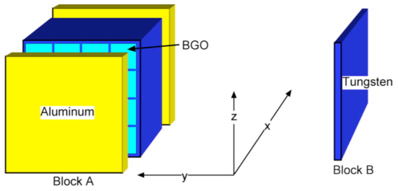
A block is a right-rectangular box which can be further subdivided into right-rectangular boxes. Here we show two possibilities: Block A, a module of BGO detectors with aluminum front and back plates and tungsten side housing; and Block B, an interblock septa of tungsten.
A ring is an axially- and radially-bounded collection of blocks (Fig. 4a): every block must fall outside an elliptical cylinder that completely contains the object being imaged and the collimator (if one is simulated). The blocks may be arranged in any orientation within the ring except that two faces of each block must be perpendicular to the tomograph axis (or, equivalently, parallel to the x-y plane).
Fig. 4.
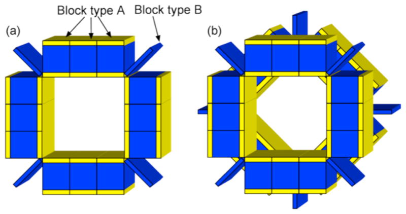
(a) A ring is a collection of blocks. Here we show a simple 4-sided ring consisting of 12 copies of Block A and 4 of Block B. Larger, more complex geometries can also be constructed, as shown in Figure 2. (b) A block detector system consists of one or more rings. Here we show a two ring tomograph created using the ring shown in (a) with the second ring rotated 45° from the first.
A block detector system consists of one or more rings placed in relation to one another (4b). Different types of rings can be combined.
III. Tracking and Detection Algorithms
The detector module in SimSET receives photons from the collimator module or, if no collimator is modeled, directly from the photon history generator, the module that tracks photons through the phantom/patient. Each photon is tracked through the detector system separately, then combined with its annihilation partner later, in the binning module. (If users want to incorporate random coincidences, deadtime, and/or pile-up into the simulation, they can either use a model-based approach, e.g. [3], [4], or create a list-mode file and use SimSET’s time-sorting and randoms-processing modules [5].)
The first step tracking a photon through a block detector system is to sample, from the exponential distribution, the number of free paths the photon will travel before it interacts [6], [7]. Next the software must determine which (if any) block the photon’s path will first intersect (Fig. 5a). Once this block is identified, the photon is projected to the nearest face of the block (the intervening space is modeled as air) and tracked through the block until the sampled number of free-paths is used up; an interaction is modeled at this point. (If the photon passes through the detector without using up the free-paths, the next block intersection is determined as in Fig. 5a. If the photon passes through all the detectors in its path without interacting it is discarded.)
Fig. 5.
(a) Upon entering the detector system, a photon is projected to the nearest face of the first block in its path. (b) The position and energy deposited is recorded for each interaction.
At the interaction point, an interaction is chosen (photoelectric absorption, Compton/incoherent scatter, or Rayleigh/coherent scatter), modeled, and the position ((xi, yi, zi)for the i’th interaction) of and energy-deposited (Ei) by the interaction recorded (Fig. 5b). If the photon scattered, its new direction is computed and tracking continues as above. The photon is tracked until it is photoabsorbed or exits the detector system.
Once a photon’s tracking is complete, a detected position and detected energy is computed for each block in which the photon interacted (Fig. 6). These are computed based on all interactions, I, in active (e.g., scintillating) areas of the block. The detected position is computed as an energy-weighted centroid, (xc, yc, zc), of these interactions
Fig. 6.
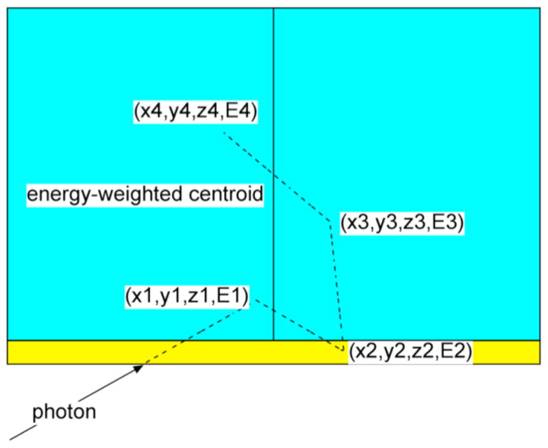
After tracking a photon the energy-weighted centroid and detected energy for a block are computed using all the interactions in the active area of that block. In this case we would use only the first, third and fourth interactions as the second interaction occurred in the front cover.
| (1) |
The detected energy, E, is computed as a Gaussian-blurred sum of these interactions
| (2) |
where G(μ, σ) is a random sample from a Gaussian distribution with mean μ and standard deviation σ, ER is the user-specified reference energy (usually the photon emission energy for SPECT or 511 keV for PET), and R%FWHM is the user-specified full-width-half-maximum (FWHM) of the Gaussian at ER as a percentage of ER. 2.354820045 is the conversion factor between the FWHM and the standard deviation of a Gaussian.
If, for a given photon, the detected energy for a given block is less than a user-specified minimum detection trigger energy, the detection is discarded for that block. If, for a given photon, the detected energy exceeds the trigger energy in more than one block, then all detections for the photon are discarded. If the trigger energy is exceeded in exactly one block, the photon is passed along to the next software module with its position and energy set to the energy-weighted centroid and detected energy for that block.
The algorithms described by (1) and (2) may be too simple for some user simulations. For instance, they do not take into account the changing scintillation light collection efficiency across the face of a typical photomultiplier tube. To address this problem SimSET includes a built-in ‘user’ function that gets called after tracking each photon. The intent of this function is to allow users to modify the detected characteristics of each photon before further processing occurs. The function has access to all the photon’s interaction information in the block detector system.
IV. Discussion
The proposed block detector simulation addresses one of the main limitations of SimSET for simulations of typical commercial PET systems. It will also allow for simulations of many non-cylindrical tomograph designs, including PEM designs, and tomographs with inserts. In the future we may add other geometric primitives (e.g., blocks with a triangular cross-section) and give the detector system the ability to move (e.g., rotations or wobbles) to further expand the range of tomographs that can be simulated.
V. Software Availability
The SimSET source code is available for free download at http://depts.washington.edu/simset/html/simset_main.html.
Acknowledgments
This work was supported in part by the National Institutes of Health under PHS grant CA42593.
Contributor Information
Robert L. Harrison, Email: roberth@u.washington.edu, Department of Radiology, University of Washington, Seattle, WA 98195 USA.
Steven B. Gillispie, Email: gillisp@u.washington.edu, Department of Radiology, University of Washington, Seattle, WA 98195 USA
Thomas K. Lewellen, Email: tkldog@u.washington.edu, Department of Radiology, University of Washington, Seattle, WA 98195 USA.
References
- 1.Lewellen TK, Harrison RL, Vannoy S. The SimSET program, in Monte Carlo calculations. In: Ljungberg M, Strand S, King M, editors. Monte Carlo Calculations in Nuclear Medicine. Philadelphia: Institute of Physics Publishing; 1998. pp. 77–92. [Google Scholar]
- 2.Shokouhi S, Vaska P, Schlyer DJ, Stoll SP, Villanueva A, Kriplani A, Woody CL. System performance Simulations of the RatCAP awake rat brain scanner. IEEE Trans Nucl Sci. 2005;52:1305–1310. [Google Scholar]
- 3.Badawi RD, Kohlmyer SG, Harrison RL, Vannoy SD, Lewellen TK. The effect of camera geometry on singles flux, scatter fraction and trues and randoms sensitivity for cylindrical 3D PET-a simulation study. IEEE Trans Nucl Sci. 2000;47:1228 – 1232. [Google Scholar]
- 4.Schmitz RE, Kinahan PE, Harrison RL, Stearns CW, Lewellen TK. Simulation of countrate performance for a PET scanner with different degrees of partial collimation. 2005 IEEE Nuclear Science Symposium Conference Record M11-150 (published on CD); 2005. [Google Scholar]
- 5.Harrison RL, Gillispie SB, Alessio AM, Kinahan PE, Lewellen TK. The effects of object size, attenuation, scatter, and random coincidences on signal to noise ratio in simulations of time-of-flight positron emission tomography. 2005 IEEE Nuclear Science Symposium Conference Record M04-4 (published on CD); 2005. [Google Scholar]
- 6.Spanier J, Gelbard EM. Monte Carlo Principles and Neutron Transport Problems. Reading, MA: Addison-Wesley; 1969. [Google Scholar]
- 7.Kahn H. USAEC Rep AECU-3259. Los Angeles: Rand Corporation; 1954. Applications of Monte Carlo. [Google Scholar]


