Abstract
In this paper we present details of a 600 MHz HTS insert (H600) double pancake (DP) windings. It will first be operated in the bore of a 500 MHz LTS magnet, achieving a frequency of 1.1 GHz. Upon completion of H600, we will embark on the final phase (Phase 3B) of a 3-Phase program began in 2000: completion of a high resolution 1.3 GHz LTS/HTS magnet. In Phase 3B, the H600 will be coupled to a 700 MHz LTS magnet to achieve the ultimate frequency of 1.3 GHz. The HTS insert is composed of two concentric stacks of double pancakes, one wound with high strength BSCCO-2223 tape, the other with YBCO coated conductor. Details include conductor and coil parameters, winding procedure, DPs mechanical support and integration to the background 500 MHz LTS magnet. Test results of individual DPs in LN2 are also presented.
Index Terms: BSCCO-2223 tape, HTS insert magnet, LTS/HTS NMR magnet, YBCO coated conductor, 1.1 GHz
I. Introduction
The final phase of our 3-Phase program, to complete a 1.3 GHz NMR magnet, started in 2000 at the MIT-Francis Bitter Magnet Laboratory (FBML). Phase 1, with a 350 MHz system, was completed in 2002 [1], [2]; and in 2007 a 700 MHz NMR system for Phase 2 was built and tested [3]. True to our original philosophy, the magnets for each phase were: i) a combination of a low-temperature superconducting (LTS) background magnet and a high-temperature superconducting (HTS) insert; ii) an HTS built as a stack of double pancake (DP) coils.
Our Phase 3 magnet is no different. Phase 3, subdivided into Phases 3A and 3B, started in 2008. Phase 3A includes a 600 MHz HTS insert (H600), operating in a 500 MHz LTS (L500) background magnet; Phase 3B combines H600 and a 700-MHz LTS background NMR magnet. A 600/700 MHz HTS/LTS combination achieves a final frequency of 1.3 GHz.
Fig. 1 shows to-scale, sketches of the magnet systems to be completed in Phases 3A and 3B.
Fig. 1.
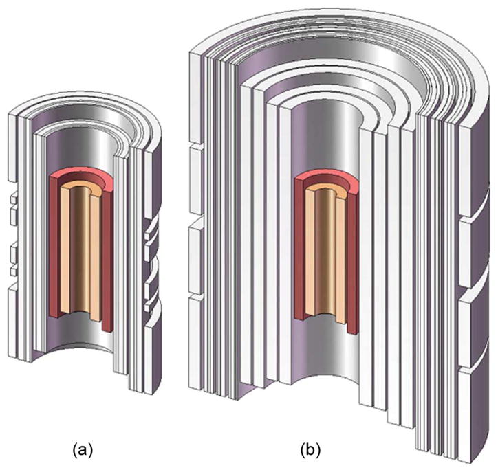
To-scale representations of the NMR magnet systems to be completed in (a) Phase 3A: 1.1 GHz and (b) Phase 3B: 1.3 GHz.
II. System Overview
As stated previously, the magnet system in Phase 3A magnet consists of a 500 MHz LTS background magnet and a 600 MHz HTS insert, generating a total field/frequency of 25.83 T/1.1 GHz. Both LTS and HTS magnets, immersed in a bath of LHe at atmospheric pressure, will be operated at 4.2 K.
III. 500 MHz LTS Background Magnet
The magnet, comprising Nb3Sn and NbTi coils, was procured, through a bidding process, from JASTEC (Japan Superconductor Technology). Operating in persistent mode, it generates an NMR-quality central field of 11.74 T (500 MHz) at 2 45.82 A. A set of superconducting shim coils, positioned on a separate former, surrounds the main coil in the helium vessel; each coil fitted with a super-conducting switch for persistent mode operation. The main parameters of the magnet are listed in Table I. The unit was tested, at the factory, in the vertical orientation and immersed in a bath of LHe at atmospheric pressure. Fig. 2 shows a photo of the magnet while a drift vs. time plot of the magnet is presented in Fig. 3.
TABLE I.
LTS Magnet Parameters
| Parameter | Value |
|---|---|
| Cold bore diameter | 273.0 mm |
| Overall diameter | 780 mm |
| Overall length | 1422 mm |
| Mass | 1200 kg |
| Resistance at RT | 7.5 W |
| Operating temperature | 4.2 K |
| Maximum central field strength | 11.74 T |
| Operating current @ 11.74 T | 245.82 A |
| Inductance | 152.4 H |
| Stored energy | 4.6 MJ |
| Drift in persistent mode @ 11.74 T | <3Hz/h |
| Field homogeneity after SC shimming: | |
| Measured field homogeneity in 17 mm dia. × 30 mm length | 0.45 ppm |
Fig. 2.
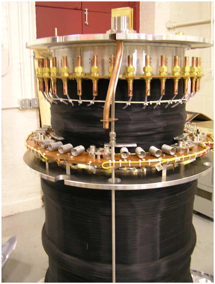
A photograph of the 500 MHz LTS magnet.
Fig. 3.
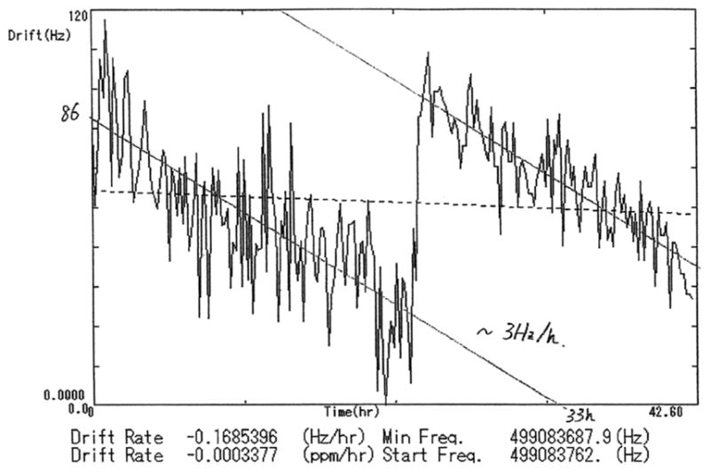
Measured drift–time plot of the 500 MHz LTS magnet.
IV. 600 MHz HTS Insert
The HTS inserts for Phases 1 and 2 of our program were each a single stack of DP coils made with high-strength stainless steel reinforced Bi-2223 conductor.
Due to the high stresses that the HTS insert will experience during operation at 1.3 GHz, Phase 3 HTS insert is made out of two nested stacks of DP coils. Two types of conductors were considered for this new insert—BSCCO-2223/Ag and YBCO [2]. Our study determined that, as commercially available, neither of these two conductors was suitable to meet the stress/strain and protection requirements of our coils; additional strengthening and/or stabilizing layers would be required. The final design of the Phase 3 HTS insert has the inner coil made of YBCO conductor while the outer coil was wound with BSCCO-2223/Ag conductor. The design was optimized to minimize peak hoop stresses in the two coils.
From a stress analysis based on force equilibrium from continuum mechanics [4], with governing equation
where σr: radial stress; σh: hoop stress; J: magnet overall current density; B: radial magnetic field inside the windings; a peak hoop strain distribution on the midplane of the two coils composing the HTS insert as operating in the background field of a 700 MHz magnet is obtained. The distribution is presented in Fig. 4.
Fig. 4.
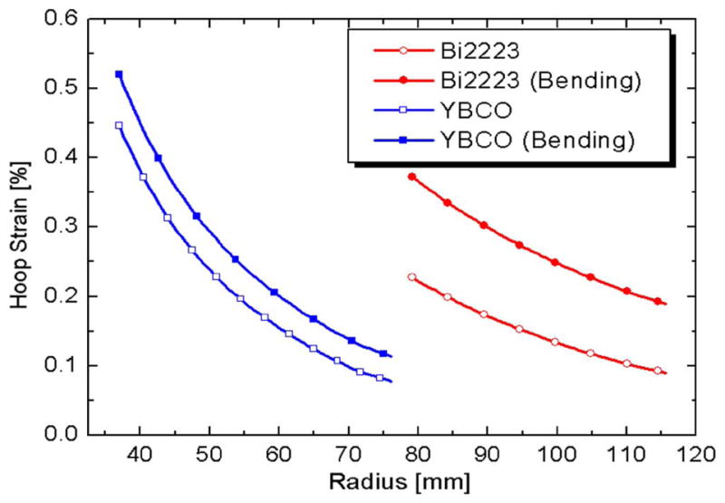
Midplane peak hoop strain of the inner (YBCO) and outer (Bi-2223/Ag) insert coils.
Note that the bending strain of the Bi-2223, 0.15%, is twice larger than that of YBCO, 0.07%. Also, even without bending strain the magnetic and thermal strain is already 0.45% in the inner coil, which is larger than the critical strain-95% Ic degradation of the Bi-2223/Ag, 0.45%. So, our choice is unique; YBCO conductor for the inner coil and Bi-2223/Ag conductor for the outer coil [5].
The YBCO conductor, Type SCS4050-AP, manufactured by SuperPower, is a coated conductor based on REBCO (Rare Earth Barium Copper Oxide).with a high-strength Hastelloy C276 substrate.
Sumitomo’s DI-BSCCO Type HT tape was chosen as the conductor for the inner coil.
Specifications for both conductors are indicated in Table II.
TABLE II.
Conductor Specifications
| SuperPower Type SCS4040-AP – Inner Coil | |
|---|---|
| Width | 4.1 mm± 0.15 mm |
| Thickness | ~0.065 mm +0.025 mm/−0.01 mm |
| Critical Current (Ic) | >100A |
| Copper Stabilizer Thickness | 10 μm (5 μm per side) ± 1 μm |
| Silver Overlay Thickness | 2.0 μm ± 0.5 μm |
| Hastelloy Substrate Thickness | 50 μm |
| Critical Tensile Stress | > 550 MPa |
|
| |
| Sumitomo DI-BSCCO Type HT-SS – Outer Coil
| |
| Width | 4.5 mm ± 0.3 mm |
| Thickness | 0.30 mm ± 0.04 mm |
| Critical Current (Ic) | ≥ 160A |
| N value (index) | N≥ 15 @ 0.1–1 μV/cm, 77 K, self field |
| Configuration | Stainless steel lamination (20 μm × 2) |
| Tensile Stress @ Room Temperature | ≥ 150 MPa |
V. Coil Fabrication
The DP coils were wound on a winding table designed and constructed at the FBML. It consisted of two payoffs: for the superconductor and the co-winding material, and a winder. The payoffs, to provide the necessary winding tension, have Warner Electric Precision Tork Model MC5.5 permanent magnet clutches mounted on the shaft of a Bodine Electric Gearmotor. The winder has the winding mandrel mounted on a Bodine Electric Gearmotor whose speed is controlled via a Bodine Electric type FPM adjustable speed/torque control. Fig. 5 presents a view of the winding table.
Fig. 5.
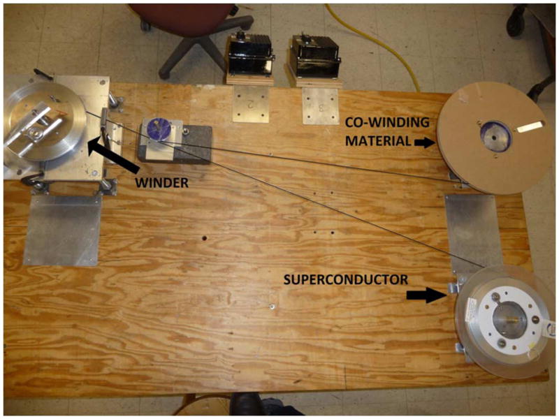
View of winding table depicting main components.
As stated earlier, our analysis concluded that none of the conductors considered for the 600 MHz HTS insert (H600) met the stress/strain and protection requirements of H600, thus making necessary the addition of strengthening/stabilizing materials. The outer coil, wound with coated Bi-2223/Ag conductor, requiring strengthening to meet the system stress/strain values, was co-wound with stainless steel type 304 FH, 4 mm wide, 50 μm thick; as wound the coil does not have inter layer insulation, the insulation is provided by the conductor/stainless steel contact resistance [4]. The inner coil, wound with coated YBCO conductor, which due to its Hastelloy C276 substrate, required only additional stabilizer material, which was co-wound with insulated copper tape 4 mm wide, 0.2 mm thick. Insulation on copper tape was 0.023-mm thick polyester applied only to one face of the tape.
Regardless of the added strengthening layers, both coils will finally have a 5 mm thick over-banding, in wire or tape form.
The key parameters of the two coils composing the 600 MHz HTS insert are listed in Table III. A photograph of a single DP of the inner and outer coils, in their approximately final position is shown in Fig. 6.
TABLE III.
Key Parameters of the 600 MHz HTS Insert
| Inner Coil | Outer Coil | |
|---|---|---|
| Conductor | YBCO | Bi-2223/Ag |
| Frequency [MHz] | 354.8 | 245.3 |
| Field contribution [T] | 8.33 | 5.76 |
| Operating temperature [K] | 4.2 | 4.2 |
| Operating current [A] | 251.0 | 251.0 |
| Overall current density [kA/cm2] | 19.94 | 15.50 |
| # of DP coils | 56 | 56 |
| # of turns per pancake | 112 | 90 |
| Inner diameter [mm] | 74.0 | 158.3 |
| Outer diameter [mm] | 142.3 | 221.3 |
| Height [mm] | 462.2 | 518.2 |
| SS over banding thickness [mm] | 5.0 | 5.0 |
| Conductor length/DP [m] | 77.6 | 107.4 |
| Total conductor length [km] | 4.35 | 6.02 |
| Co-winding material | Insulated Copper | Stainless Steel |
Fig. 6.
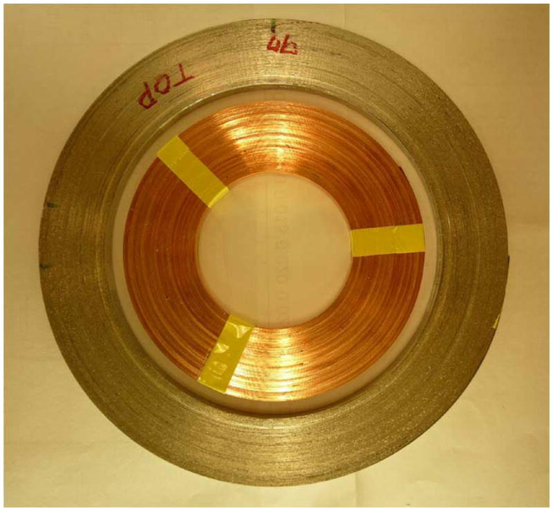
A single DP of an inner and outer coil in their approximately final position.
VI. Testing and Results
The coils so far fabricated have been tested individually, in a bath of LN2 (77 K, 1 atmosphere), for their current carrying capacities and center fields. They are instrumented with voltage taps and, a Hall sensor located at the center of the coil. Fig. 7 presents a general view of the experimental setup with a single Bi-2223/Ag DP coil.
Fig. 7.
Test setup with a single Bi-2223/Ag DP coil.
Fig. 8 depicts a current vs. voltage chart of a typical Bi-2223/Ag wound DP, which at the 1 μV/cm criterion indicates an average Ic of 71.2 A.
Fig. 8.
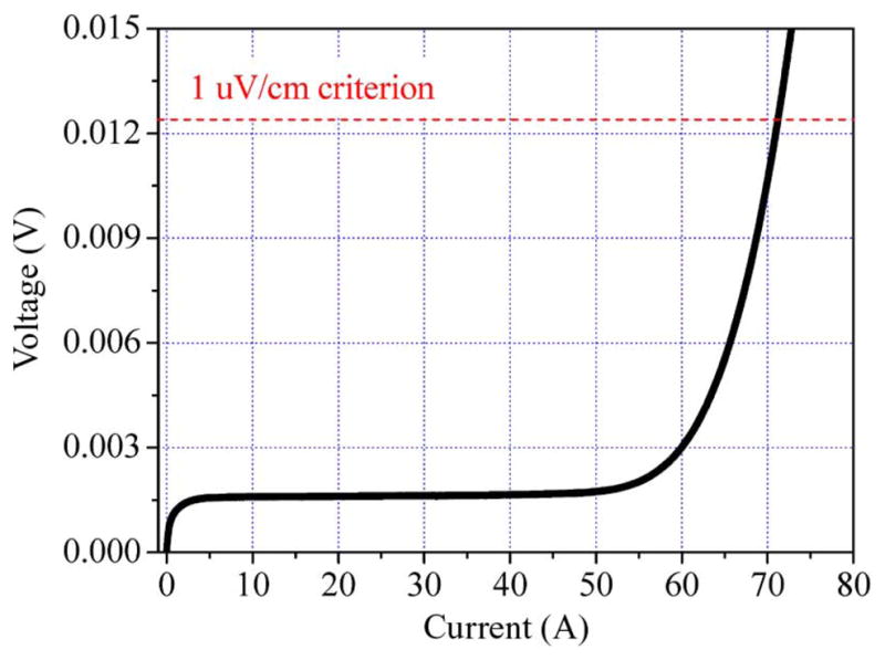
Current vs. voltage plot of a Bi-2223/Ag DP coil. Ic = 71.2 A, n – value = 12.
A similar graph for a DP wound with YBCO conductor is presented in Fig. 9, in this case under the same1 μV/cm criterion, the measured Ic is 47 A.
Fig. 9.
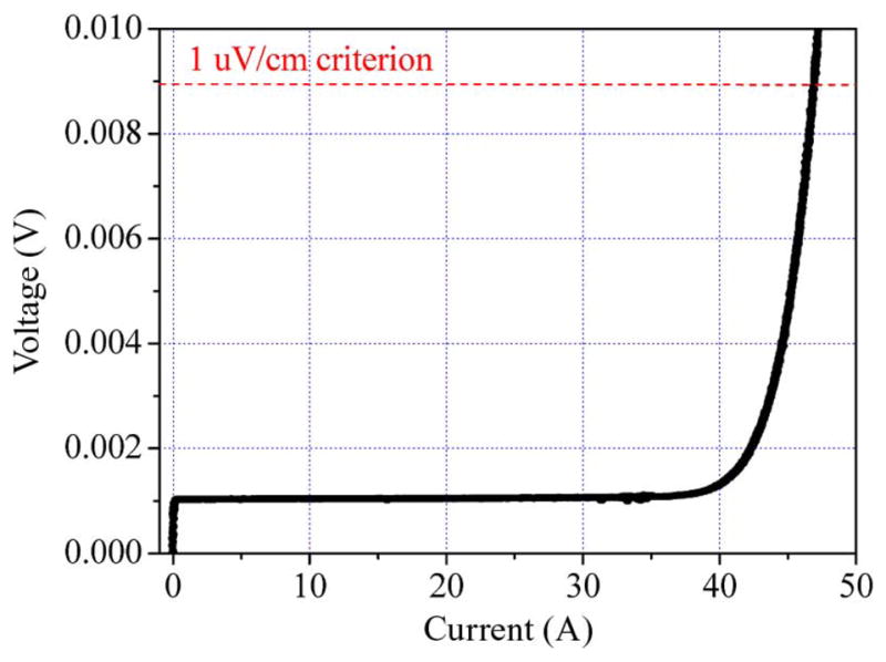
Current vs. voltage plot of a YBCO DP coil. Ic = 47 A, n – value = 21.
During testing the n-value of each coil was also determined. On average, n-value for the Bi-2223/Ag DP coils is 12, while for the YBCO DP coils, it is 21.
VII. Testing and Results
The fabrication of the 600 MHz HTS insert advances at a steady pace. To date about 50% of all DPs have been wound and individually tested. Next, it will be their assembly to form the inner and outer coils.
VIII. Conclusions
Building of the 600 MHz HTS insert progress as scheduled, to date approximately 40% of all the DPs have been wound and individually tested.
Acknowledgments
The authors would like to thank David F. Johnson for his help in fabricating and setting up the winding table. Also the invaluable help of Daniel Jordan, a Co-op student from Northeastern University, in winding and testing the coils is recognized here.
This work was supported in part by the National Center for Research Resources, National Institute of General Medical Sciences, and National Institute for Biomedical Imaging and Bioengineering.
Footnotes
Color versions of one or more of the figures in this paper are available online at http://ieeexplore.ieee.org.
References
- 1.Bascuñán J, Bobrov E, Lee H, Iwasa Y. A low- and high-temperature superconducting NMR magnet: Design and performance results. IEEE Trans Appl Supercon. 2003;13(1550) [Google Scholar]
- 2.Iwasa Y, Bascuñán J, Hahn S, Tomita M, Yao W. High-temperature superconducting magnets for NMR and MRI: R&D activities at the MIT francis bitter magnet laboratory. IEEE Trans Appl Supercond. 2010 June;20(2):718–721. doi: 10.1109/tasc.2010.2040073. [DOI] [PMC free article] [PubMed] [Google Scholar]
- 3.Bascuñán J, Lee H, Bobrov E, Hahn S, Iwasa Y. A 700 MHz LTS/HTS NMR magnet—A Status Report. IEEE Trans Appl Supercon. 2006;16(2) [Google Scholar]
- 4.Iwasa Y. Case Studies in Superconducting Magnets. 2. Vol. 3 New York: Springer; 2009. [Google Scholar]
- 5.Hahn S, Bascuñán J, Yao W, Park DK, Iwasa Y. Two HTS options for a 600 MHz insert of a 1.3 GHz LTS/HTS NMR magnet: YBCO and BSCCO. Physica C. 2010 doi: 10.1016/j.physc.2010.05.194. accepted for publication. [DOI] [PMC free article] [PubMed] [Google Scholar]


