Abstract
Utilization of external motion tracking devices is an emerging technology in head motion correction for MRI. However, cross-calibration between the reference frames of the external tracking device and the MRI scanner can be tedious and remains a challenge in practical applications. In this study, we present two hybrid methods, which both combine prospective, optical-based motion correction with retrospective entropy-based autofocusing in order to remove residual motion artifacts. Our results revealed that in the presence of cross-calibration errors between the optical tracking device and the MR scanner, application of retrospective correction on prospectively corrected data significantly improves image quality. As a result of this hybrid prospective & retrospective motion correction approach, the requirement for a high-quality calibration scan can be significantly relaxed, even to the extent that it is possible to perform external prospective motion tracking without any prior cross-calibration step if a crude approximation of cross-calibration matrix exists. Moreover, the motion tracking system, which is used to reduce the dimensionality of the autofocusing problem, benefits the retrospective approach at the same time.
Keywords: motion correction, optical motion correction, prospective motion correction, retrospective motion correction, entropy, autofocusing
1. Introduction
Correction of involuntary patient motion is a critical, yet still unsolved problem in MRI. Artifacts caused by patient motion can result in impaired or non-diagnostic image quality that warrant re-scanning or limit diagnostic confidence. Particularly, for certain patient populations, such as children, elderly, or people with specific medical conditions (i.e. Parkinson's disease, stroke), it is key to incorporate motion correction methods to increase the reliability of the imaging data.
Amongst other prospective motion compensation methods (1–3), optical systems have been used very successfully to track head motion and then compensate for involuntary pose changes of these patients by adapting the scan-plane orientation (4–9). Recent optical approaches used either a monovision (8–10) or stereovision setup (4–7) and cameras were placed either outside (4–6,8) or inside (7,9,10) the scanner bore. Either way, the current pose information derived from the optical pose tracker is immediately sent back to the radio frequency (RF) and gradient controller of the scanner. Consequently, the scanning slice or slab remains ‘locked’ to the anatomy under examination even if the patient is moving. Since the ‘external’ optical pose tracking operates independent from the MR data acquisition process, it does not penalize MR scan performance and the rate of possible adaptations to pose changes is theoretically determined by frame rate of the pose tracker.
The general advantages of prospective correction systems are: 1) the ability to correct for motion with minimal or no changes to the pulse sequence (i.e., no navigator echoes or customized trajectories), and thus providing pulse sequence design flexibility; 2) data consistency (no undersampling in k-space or no change in effective directional encoding of flow or diffusion (11,12)); and 3) the ability to avoid spin-history effects and hence provide better signal stability. Apart from prospective-only or retrospective-only systems, combined approaches that use both have also been proposed to remove residual errors on the data after prospective correction (13,14).
Motion correction systems that employ external tracking devices for pose detection require a cross-calibration procedure prior to the start of the scan. For the remainder of this article, this calibration procedure is also called the scanner-camera cross-calibration. The cross-calibration is required to determine the geometric relation between the reference frames of the MR scanner and the external tracking device. That way, the positional changes detected by the external device can be converted into positional adjustments of the MRI scan volume.
Although our 60s cross-calibration has proven very reliable (9,10), we will show that errors in scanner-camera cross-calibration can lead to erroneous pose adjustments and image artifacts. Thus, having a fallback mechanism in the event of sub-optimal cross-calibration due to involuntary patient motion during the calibration scan, subtle changes of the setup between the cross-calibration procedure and the patient scan, or in the extreme case when no cross-calibration is performed will therefore be of considerable relevance for prospective motion correction techniques.
In this study, we propose a joint prospective and retrospective method to perform rigid head motion correction. Specifically, we will introduce two retrospective methods that employ entropy-based autofocusing (15,16) following a prospectively motion corrected data acquisition to compensate for inaccurate scanner-camera cross-calibration. Ultimately, we will also demonstrate the potential for performing prospective optical motion correction without the need for cross-calibration if an approximate cross-calibration matrix, such as from a previous MR scan or from an off-line calibration, exists.
2. Materials and Methods
2.1 Optical Prospective Motion Correction
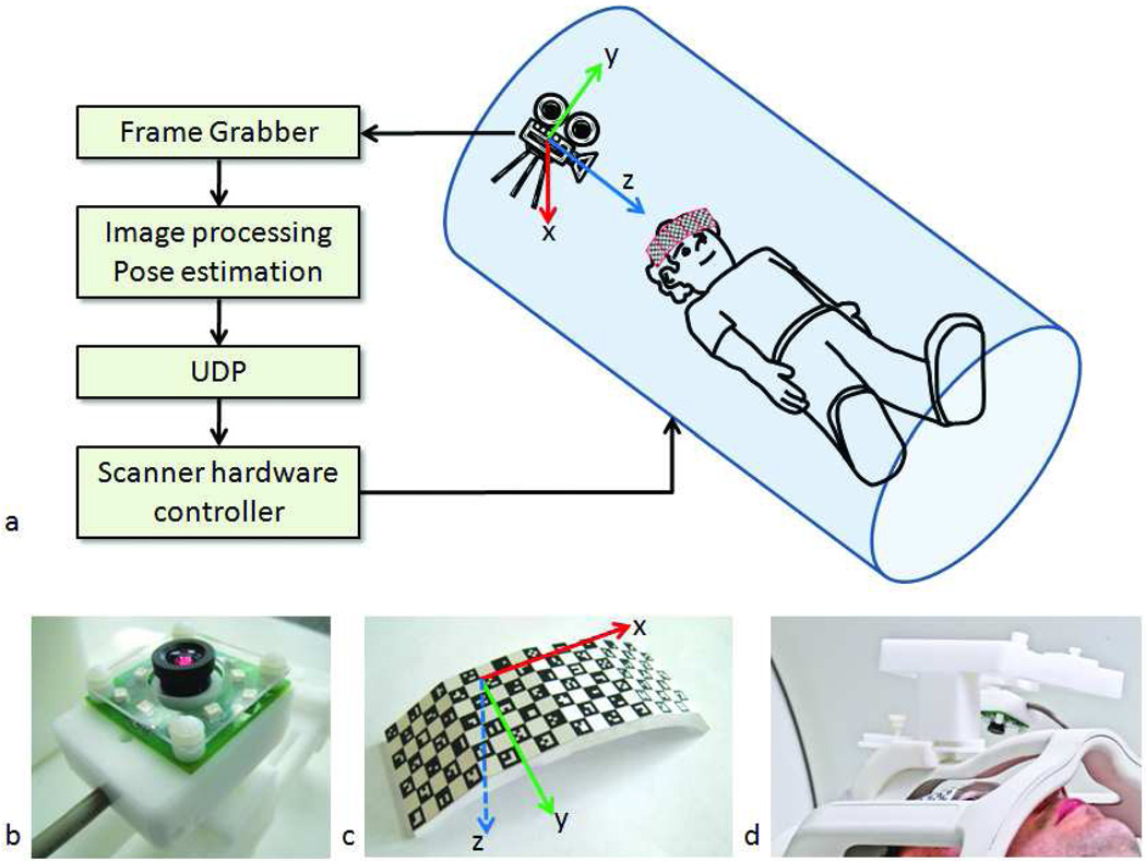
The optical tracking system used for this study is shown in Fig. 1 and has been described in detail earlier (9). This system used a single camera (Fig. 1b) which was mounted on the head coil and a self-encoded checkerboard marker (Fig. 1c,d), which in turn was attached rigidly to the patient's forehead via an adhesive tape to track head motion (10). The checkerboard pattern was detected automatically by a real-time processing software interfaced to the tracking camera, and the relative pose changes were sent back to the scanner in real-time to update gradients, RF frequency, and readout phase to adapt the MR scan volume for pose changes. The latency of the system varied between 60 to 150 ms depending on external factors such as the view of the marker, lighting conditions, etc. In order to make up for this delay, k-space lines were reacquired when the detected motion was above 1° rotation or 1mm translation. For the 3D acquisition used in this study, ~50 k-space lines were reacquired to be on the safe side. Rigid body motion was assumed throughout.
Figure 1.
System setup. An MR-compatible camera was mounted on the head coil inside the scanner bore (a,d). The camera (b) took images of a self-encoded marker (c) that was attached to the patient's forehead. These images were processed by an external laptop where 1) the squares on the marker were segmented out; 2) the pose of the marker was estimated; and 3) the 6 parameters (i.e. 3 rotations and 3 translations) to update the scanner geometry were sent to the scanner RF and gradient hardware controller. This allowed the scan plane to follow the subject's head in real-time.
2.2 Mathematical Description of Prospective Motion Correction
For successful motion correction, the position of the scan plane needs to remain fixed relative to the anatomy. Thus, given the positional change of the marker as detected by the camera, one needs to find the geometry update that needs to be applied to the scanner. As described in (6,9), the geometry update that needs to be applied to the scanner is given by the following expression:
| (1) |
Here, T is a 4×4 transformation matrix that includes rotation and translation and Ta→b represents the transformation from coordinate frame a to b. c represents the camera position, m0 initial marker position, mi represents marker position at time i, s0 represents initial MR scan-plane coordinate frame and si represents MR scan-plane coordinate frame at time i. Tm0→c and Tc→mi were determined using computer vision theory as described in (10,17). In this method, first, the quads of the checkerboard pattern were detected (Fig. 1c). Then, the 2D barcodes in each quad were identified, which allowed to establish a one-to-one correspondence between the detected quads in the camera image and the quads in the geometrical model of the marker. Finally, these correspondences were exploited to determine the 3D pose of the marker using a pinhole camera model (17). Tc→s0 is called the scanner-camera cross-calibration matrix and it was obtained using a calibration scan.
To perform camera-scanner cross-calibration (i.e., determination of Tc→s0), a marker was used that is detectable by both the MR scanner and the camera. Moreover, the exact position of the MR-detectable part was known relative to the optically detectable part of the marker. Thus, the position and orientation of the camera relative to the MR-scanner reference frame could be determined by imaging the MR-visible and optically-visible components of the marker simultaneously. Such a hybrid marker was manufactured by adding an MR-detectable component to the self-encoded pattern shown in Fig. 1b. Cylindrical wells were drilled at the bottom of the marker and filled with 5% agar solution and tightly sealed afterwards (Fig. 8e).
Figure 8.
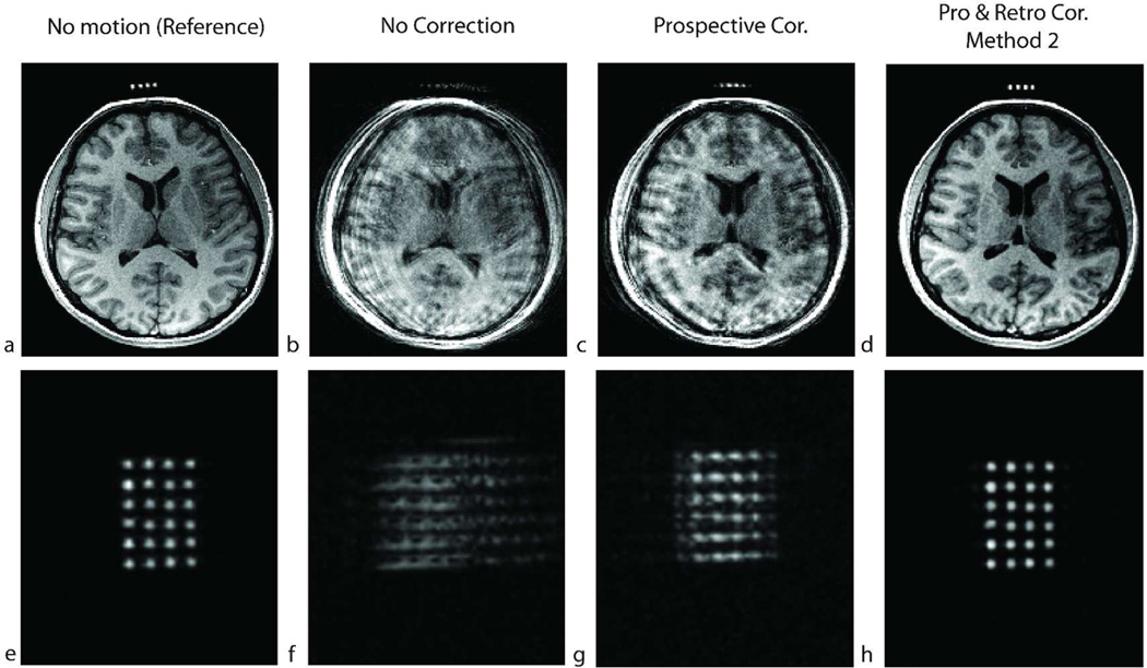
Results of a high-resolution (256×256×192) in-vivo experiment in the presence of shaking motion throughout the scan for subject 6. The resolution in this scan is similar to what would be used for a cross-calibration scan. a–d show an axial slice and e–f show an oblique slice that goes through the agar droplets. The non-corrected image showed motion artifacts and the agar droplets were not identifiable in (b) and (f). After prospective correction, the artifacts remained because the true cross-calibration between the camera and the scanner was unknown (c,g). After retrospective correction using method 2, the agar droplets were distinguishable, and could be used to perform the cross-calibration (d,h).
The MR pulse sequence used for the cross-calibration scan was an axial fast gradient-recalled echo (GRE) sequence with the following parameters: TR/TE = 8.4/2.9msec, 128×128×48 resolution, FOV = 12cm, slice thickness = 1mm, NEX=2, readout bandwidth=7kHz, scan time=52 seconds. The scan parameters were chosen so that potential susceptibility artifacts are negligibly small.
After the calibration scan was completed, the DICOM images were transferred to the external processing laptop. Here, the agar-filled wells were segmented out and ordered using a semi-automatic segmentation algorithm, and the centroids of the holes were determined in MATLAB (The MathWorks, Inc., Natick, MA, USA). Specifically, the three axes defining the marker geometry were extracted by establishing the one-to-one correspondence between the detected centroids and the known grid pattern. The large number of grid points (i.e. 6×4 = 24) provided increased robustness for estimation of the position and orientation of the marker in the scanner, i.e., Tm0→s0, over straightforward segmentation. The position and orientation of the optically detectable part of the marker with respect to the camera was also determined using computer vision theory as described above. This step gave Tc→m0. By combining these two matrices the relative position and orientation of the camera with respect to the scanner can be written as:
| (2) |
2.3 Retrospective entropy-based autofocusing
MR motion correction using entropy criterion was first described by Atkinson et al. (15,16). The entropy of an image is given by:
| (3) |
where ρ is the image pixel index, nρ is the number of pixels in the image, Iρ is the magnitude of image intensity. Itotal is the total image energy and is given by:
| (4) |
If the total image energy given by Eq. 4 is distributed uniformly over all pixels such that every pixel has the same grayscale value, the image entropy will be maximum and can be expressed by . On the other extreme, if all the image energy is concentrated on one pixel, the entropy will be minimum, i.e., Emin =0. For images containing small structures, such as the brain, motion causes blurring and aliasing (i.e. ghosting), which will, in turn, spread the image energy from one pixel to multiple pixels. This will increase image entropy as described above. Thus, minimum entropy will imply less motion artifacts. This is the basic idea that is used in entropy-based autofocusing for retrospective motion correction. Instead of requiring additional navigator data or data redundancy (e.g. self-navigated motion correction (18)), entropy-based auto-correction uses the image data itself to remove motion artifacts. This makes entropy the natural choice of cost function for our application. Atkinson et al suggested that assuming arbitrary (rigid body) motion between each k-space line, the motion parameters (relative to a reference k-space line) that minimize the image entropy can be determined using an iterative algorithm (16).
One disadvantage of motion correction using entropy approach is that, since arbitrary motion is allowed between each k-space line, the number of unknowns is very large. As an example, for a 3D MR acquisition with 192×192×96 resolution, the number of motion parameters (3 rotations and 3 translations) would be (192×96 − 1)×6. Since the dimensionality of this minimization problem is impractical, most entropy-based autofocusing algorithms use a multiresolution approach. That is, they divide k-space into segments (15,16,19) to yield a more manageable dimensionality. Moreover, the application of entropy-based motion correction is also limited to 2D because in 3D acquisitions, the number of phase encoding steps is much higher than in 2D and motion can occur between each phase encoding. In this study, the tracking data from the optical system is used to reduce the dimensionality of the problem. This allows autofocusing to be applied even to 3D sequences.
2.4 Combined Optical Prospective and Entropy-Based Retrospective Motion Correction
In this section, a method that uses the combination of prospective motion correction and retrospective entropy-based autofocusing will be described. Specifically, two methods will be introduced: 1) segmentation-based autofocusing; and 2) ‘cross-calibration matrix’-based autofocusing. Both of these retrospective methods were applied on prospectively corrected data to remove residual errors, that is, for both methods, optical tracking and real-time scan-plane adaption was turned on.
2.4.1 Segmentation-based autofocusing – Method 1
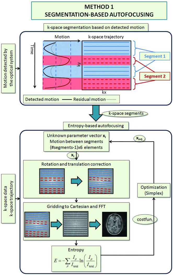
The flowchart for segmented autofocusing is shown in Fig. 2. First, the position of the head during the acquisition of each k-space line was measured using the optical tracking system. This was made possible by the reacquisition strategy utilized by our system, which guaranteed that for each k-space line, an accurate and up-to-date pose estimate was available. Thereafter, lines acquired at similar head positions were grouped together to form k-space segments. Inside these segments, the range of detected motion was not greater than a specified threshold so that within a segment, the head position and orientation can be approximated to be constant. Thus, instead of trying to find the motion between each k-space line, only the motion between these k-space segments was determined, reducing the dimensionality of the problem. This method relies on two assumptions:
Even if the pose estimation of the tracking device is inaccurate, similar head positions will result in similar pose estimates, and vice versa. Since, for each camera image, there is a unique set of 6 pose parameters (i.e., 3 rotations and 3 translations), this assumption is satisfied unless the inaccuracy in pose estimation is highly non-linear, which is highly unlikely if the optical hardware is of adequate quality.
The motion is grossly corrected by the optical adaptive motion correction system so that the residual motion remaining on the data is considerably lower than the actual subject motion. This means that the use of the optical tracking system does not create additional motion artifacts. This assumption can be satisfied in practical situations if the camera is mounted on similar locations on the head coil and intrinsic camera calibration is accurate.
Figure 2.
Segmentation based autofocusing algorithm. The motion information obtained from the motion tracking system is shown in black (upper part of the figure). Due to errors in cross-calibration, this tracking information is not 100% accurate, and residual error remains on the k-space data, which is shown with a dotted line. To eliminate this residual error, first, the k-space data was divided into segments using the tracking information provided by the optical system. Inside these segments, the patient position was assumed to be the same. Next, only the motion between the segments was determined using iterative entropy-based autofocusing algorithm.
After segmentation, the 6 motion parameters (i.e. 3 rotations and 3 translations) in each segment were determined using an iterative Nelder-Mead simplex method (20). At each iteration, the motion parameters were applied to the corresponding segments by rotating and applying a linear phase to the k-space lines. Then, gridding was performed on the 3D k-space data using post-density compensation (21) and a Kaiser-Bessel kernel (22), and the gridded data was Fourier transformed into image space. Next, the image entropy was determined, and the motion parameters were updated for the next iteration (Fig. 2). The MATLAB function fminsearch, which contains an implementation of Nelder-Mead simplex method, was used for optimization.
2.4.2 ‘Cross-calibration matrix’-based autofocusing – Method 2
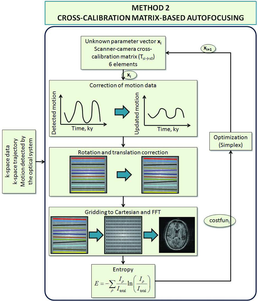
The flowchart explaining ‘cross-calibration matrix’-based autofocusing is shown in Fig. 3. As opposed to segmentation-based autofocusing, this method did not divide the k-space into segments within which the head pose was constant. Instead, each k-space line was assumed to have been acquired at a different head position. However, it was also assumed that any residual motion on the k-space data was caused entirely by the inaccuracies in the scanner-camera ‘cross-calibration matrix’ (Eq. 2). As explained below, with this assumption, the residual motion corresponding to each k-space line (acquired at time i) could be determined using the motion detected by the optical system (Tsi→s0) and the actual cross-calibration matrix . The former was already known, and the latter remained to be determined using iterative optimization. Thus, the number of unknowns to be determined was 6. In conclusion, for this method, the aim was to determine the true ‘cross-calibration matrix’ that resulted in the image with the lowest entropy.
Figure 3.
Cross-calibration matrix based autofocusing algorithm. In this method, the residual error on the k-space data was assumed to originate from the inaccuracies in the scanner-camera cross-calibration matrix. Thus, the residual motion between each k-space line was a function of the difference between the used and corrected cross-calibration matrices. So, in this method, the cross-calibration matrix was optimized to find the image with minimum entropy.
For the mathematical description of this method, the reader is referred to Eq. [1]. Here, one assumes that the cross-calibration matrix Tc→s0 is inaccurate, which can be described by:
| (5) |
where is the corrected cross-calibration matrix and T(cor) is the correction matrix. Then, from Eq. [1]:
| (6) |
Since part of the motion is already corrected prospectively, the residual motion that still needs to be corrected for is given by:
| (7) |
Combining Eqs. 6 and 7, one gets:
| (8) |
In Eq. 8, is different for each time point, which also means that it is different for each line in k-space. is the update applied to the k-space data for each iteration of the entropy-based autofocusing. In our case, Ts0→si and Tsi→s0 were already known, and T(cor) was determined using iterative optimization. Again, the iterative optimization was carried out using the fminsearch function in MATLAB that uses the Nelder-Mead simplex algorithm.
2.4.3 Data Processing and 3D Gridding
Retrospective correction was performed on a high performance server equipped with 2 Intel® Xeon ® CPUs (X5570@2.93 GHz, Quad core with hyper-threading, based on the Intel’s Nehalem microarchitecture) and 24GB of memory. Nearly all of the post-processing time was dominated by 3D gridding. Gridding was performed using 16 parallel threads with Open Multi-Processing (OpenMP) library. The gridding code was written in C++ and interfaced into MATLAB.
2.5 In-Vivo Experiments
All experiments were performed on a 1.5T whole-body clinical MR scanner (GE Signa, 15.M4, GE Healthcare, Milwaukee, WI) using either the quadrature head coil (GE Healthcare, Milwaukee, WI) or the 8-channel head array coil (In Vivo Corp., Orlando, FL, USA) for signal reception and the built-in quadrature body coil for signal transmission. Table 1 shows a summary of all the in-vivo experiments performed for this study. Two types of axial 3D spoiled gradient echo (SPGR) acquisitions were used with different resolutions: 1) TR/TE=9.5/4.1ms, flip angle α=30°, acquisition matrix = 192×192×96, slice thickness = 1.5mm, FOV=240mm, readout bandwidth=±15kHz and 2) TR/TE=12.0/5.2ms, flip angle α=30°, acquisition matrix = 256×256×192, slice thickness = 1mm, FOV=260mm, readout bandwidth=±15kHz. For both acquisitions, a non-selective RF pulse was used and the readout was in the A/P direction. Faster and slower phase encoding were in the S/I and R/L directions, respectively. First, scanner-camera cross-calibration was performed on a volunteer (9). However, no data acquisition was done on this subject. Then, six healthy subjects (ages 27–39) were scanned by intentionally using the previously obtained cross-calibration data without running any further cross-calibration procedures. For these subjects, the camera position was adjusted for optimum field-of-view as required by the different head shapes and marker placements for these subjects. Three types of motion were tested: 1) multiple in-plane rotations around the S/I axis of the subject (i.e. shaking); 2) multiple through-plane rotations around the R/L axis of the subject (i.e. nodding); and 3) mixed shaking and nodding. Each motion experiment was repeated with and without prospective motion correction to yield two datasets. The prospectively corrected dataset was reconstructed using 3 different methods, which eventually gave four reconstructed volumes per motion experiment: 1) prospective correction off, regular fast Fourier transform (FFT) based reconstruction; 2) prospective correction on, regular fast Fourier transform (FFT) based reconstruction; 3) prospective correction on, reconstruction with segmentation-based autofocusing (method 1) with a binning threshold of 3° for rotation and 3mm for translation; and 4) prospective correction on, reconstruction with ‘cross-calibration matrix’-based autofocusing (method 2). For each subject, a scan with no intended motion was also acquired for comparison.
Table 1.
The experiments performed in this study and the corresponding average edge strength (AES) values.
| Coil type | Acquisition resolution |
Motion type |
Motion range (no cor.) |
Motion range (pros. cor.) |
# Segments for method 1 |
AES no cor. |
AES pros. cor. |
AES pro&retro method 1 |
AES pro&retro method 2 |
|
|---|---|---|---|---|---|---|---|---|---|---|
| Subject 1 | Birdcage head | 192×192×96 | Shaking | 15.0° 10.5mm | 19.1° 13.8mm | 4 | 0.64±0.04 | 0.73±0.05 | 0.85±0.06 | 0.87±0.05 |
| 192×192×96 | Nodding | 10.6 ° 9.2mm | 11.3° 7.1mm | 3 | 0.70±0.06 | 0.74±0.06 | 0.89±0.06 | 0.89±0.06 | ||
| Subject 2 | Birdcage head | 192×192×96 | Shaking & Nodding | 24.9 ° 88.6mm | 26.5° 19.8mm | 8 | 0.66±0.10 | 0.90±0.12 | 0.95±0.14* | 0.99±0.15 |
| 192×192×96 | Shaking & Nodding | 24.9 ° 88.6mm | 31.0° 20.1mm | 10 | 0.66±0.10 | 0.72±0.10 | 0.85±0.12* | 0.98±0.15 | ||
| Subject 3 | 8ch head | 192×192×96 | Shaking | 24.9 ° 19.6mm | 23.8° 14.6mm | 6 | 0.71±0.09 | 0.77±0.09 | 0.85±0.11 | 0.91±0.11 |
| 192×192×96 | Shaking & Nodding | 20.0 ° 12.2mm | 18.4° 11.8mm | 8 | 0.77±0.09 | 0.82±0.10 | 0.84±0.10* | 0.92±0.11 | ||
| Subject 4 | 8ch head | 192×192×96 | Shaking | 25.0 ° 7.2mm | 24.3° 5.6mm | 4 | 0.65±0.02 | 0.64±0.03 | 0.70±0.03* | 0.80±0.02 |
| 192×192×96 | Shaking & Nodding | 20.5 ° 8.4mm | 23.7° 7.5mm | 8 | 0.66±0.02 | 0.64±0.03 | 0.77±0.03 | 0.74±0.03 | ||
| Subject 5 | 8ch head | 192×192×96 | Shaking | 34.9 ° 14.0mm | 40.6° 12.4mm | 5 | 0.60±0.08 | 0.54±0.06 | 0.58±0.06* | 0.64±0.06 |
| 192×192×96 | Shaking & Nodding | 34.6 ° 16.8mm | 39.5° 17.9mm | 11 | 0.68±0.07 | 0.71±0.06 | 0.72±0.07* | 0.79±0.08 | ||
| Subject 6 | 8ch head | 256×256×192 | Shaking | 20.4° 12.4mm | 12.6° 7.1mm | 3 | 0.60±0.02 | 0.72±0.02 | 0.64±0.03* | 0.88±0.03 |
For the third subject, scanner-camera cross-calibration was also performed at the end of the scan in order to compare the true, prospective, and retrospective transformation of the scan-plane. The true transformation refers to the actual (i.e., gold standard) transformation of the scan plane in order to accurately correct for the head motion. True transformation was determined using the correct cross-calibration scan. The prospective transformation refers to the “wrong” transformation that was applied during prospective motion correction. The retrospective transformation was obtained from the results of retrospective autofocusing. If retrospective correction works well, we expect the true and retrospective transformations to be similar.
2.5.3 Quality Metric
The most significant effect of motion is blurring and loss of edge structures due to misregistration and ghosting. Thus, in order to quantify the amount of motion artifacts remaining in the images, we used the “average edge strength” (AES) metric defined as:
| (9) |
Here, is the 2D image grayscale value at pixel location ρ and slice z. Gx and Gy represent convolution of the operand, the image , with the x- and y-edge detection kernels [−1 −1 −1; 0 0 0; 1 1 1] and [−1 0 1; −1 0 1; −1 0 1] to get the grayscale edge images . is a binary image that specifies the locations of the edges in slice z and was obtained using the Canny edge detector (23). Thus, the numerator in Eq. (9) defines the “total edge energy”, and the denominator is the “number of edge pixels” in the image. In order to eliminate the non-motion related artifacts at the most superior and inferior slices, AES(z) was calculated for the middle 40 slices only. AES was calculated for all datasets with different motion types (no motion, shaking, nodding, shaking & nodding) and different correction strategies (no correction, prospective correction, prospective & retrospective autofocusing). Thereafter, the AES(z) values were normalized by the corresponding slice at the “no motion” dataset, which was deemed to be the gold standard. Then, for each dataset, the mean and standard deviation of AES(z) over the slice index z was tabulated.
3. Results
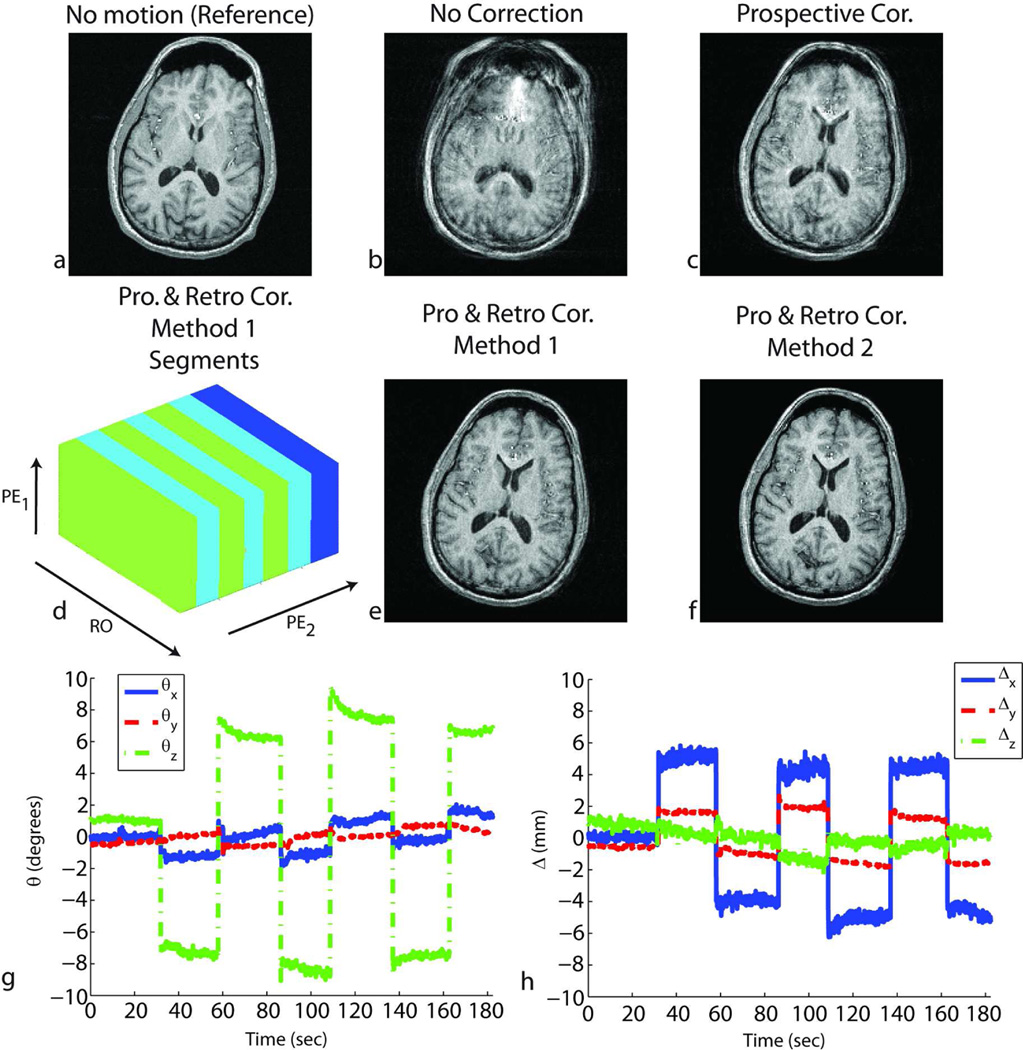
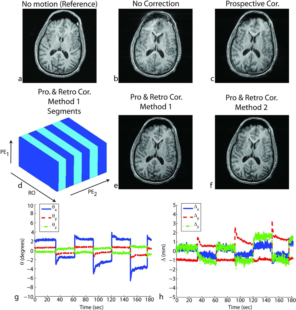
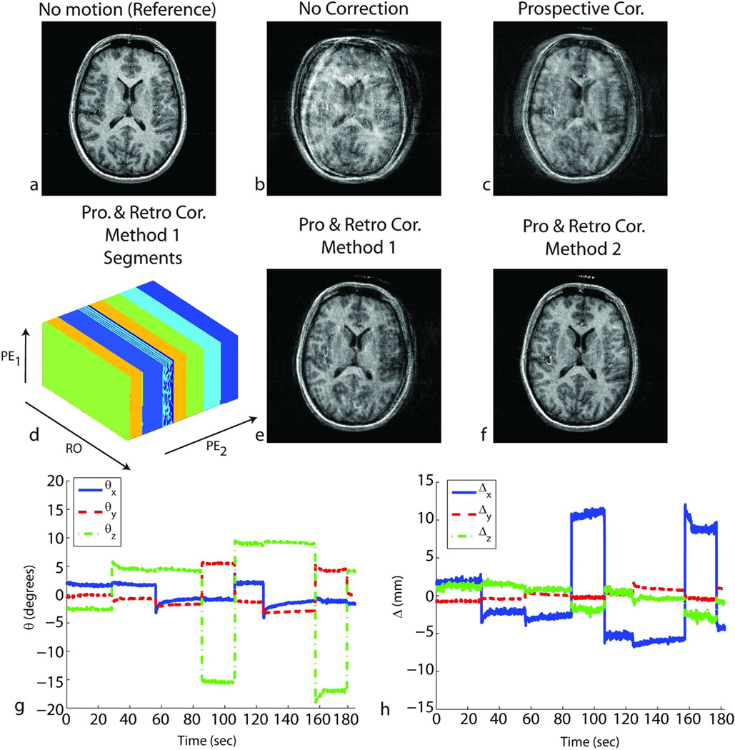
Figures 4, 5, 6 and 8 show the result of in-vivo experiments for subjects 1, 2 and 6. Figures 4 and 5 correspond to results from subject 1, Fig. 6 from subject 2 and Fig.8 from subject 6. Table 1 summarizes the experiments performed for all the subjects. The quality metric (i.e., AES) values obtained from the four reconstructed volumes for each experiment are also reported in Table 1. When prospective motion correction was not running, the images showed significant motion artifacts (Figs. 4b, 5b, 6b, 8b). These artifacts were partly corrected when prospective motion correction was turned on (Figs. 4c, 5c, 6c, 8c). The images after prospective correction still showed some artifacts because the ‘cross-calibration matrix’ used for these subjects were from a different scan (Figs. 4c, 5c, 6c, 8c). For these experiments, retrospective autofocusing using method 2 improved the image quality significantly (Figs. 4f, 5f, 6f, 8d). This was also shown by the higher AES values obtained with the combined approach using method 2 in Table 1. For subject 1, method 1 worked as well as method 2 (Figs. 4e, 5e) whereas for subjects 2 and 6, the quality of the image reconstructed using method 2 was significantly better than the one reconstructed with method 1 (Figs. 6e). In general, it was observed that the convergence of method 2 was more robust and faster compared to that of method 1. Table 1 shows that the combined iterative approach using method 1 did not converge to yield adequate image quality in 7 of the 11 cases (marked with * in Table 1) whereas method 2 improved the image quality in all of the 11 cases.
Figure 4.
Results of in-vivo experiments in the presence of shaking motion (around the S/I axis of the subject) throughout the scan for subject 1. Without correction, the reconstructed image shows motion-related blurring (b). After prospective correction, residual artifacts remained due to the inaccurate cross-calibration between camera and scanner references frames (c). Retrospective correction using either method 1 – segmented autofocusing (e) or method 2 – cross-calibration matrix-based autofocusing (f) improved the image quality. For method 1, the k-space segments in which the head position was approximately the same are shown in (d). RO corresponds to the readout axis, and PE1 and PE2 correspond to fast and slow phase encoding axes, respectively. The rotations (g) and translations (h) performed by the volunteer are also shown.
Figure 5.
Results of in-vivo experiments in the presence of nodding motion (around the R/L axis of the subject) throughout the scan for subject 1. Without correction, the reconstructed image showed motion-related blurring (b). After prospective correction, residual artifacts remain due to the inaccurate cross-calibration between camera and scanner reference frames (c). Retrospective correction using either method 1 – segmented autofocusing (e) or method 2 – cross-calibration matrix-based autofocusing (f) improved the image quality. For method 1, the k-space segments in which the head position was approximately the same are shown in (d). RO corresponds to the readout axis, and PE1 and PE2 correspond to fast and slow phase encoding axes, respectively. The rotations (g) and translations (h) performed by the volunteer are also shown.
Figure 6.
Results of in-vivo experiments in the presence of shaking and nodding motion throughout the scan for subject 2. Without correction, the reconstructed image shows motion-related blurring (b). After prospective correction, residual artifacts remain due to the inaccurate cross-calibration between camera and scanner reference frames (c). Retrospective correction using method 2 – cross-calibration matrix-based autofocusing (f) improved the image quality. However, due to the large number of unknowns caused by the complicated motion pattern, method 1-segmentation based autofocusing did not yield good image quality (e). For method 1, the k-space segments in which the head position was approximately the same are shown in (d). RO corresponds to the readout axis, and PE1 and PE2 correspond to fast and slow phase encoding axes, respectively. Some of the estimated locations can fall onto the border separating two segments, which explains the color pattern observed on segment 3. The rotations (g) and translations (h) performed by the volunteer are also shown.
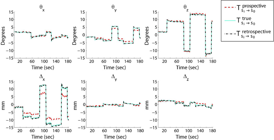
Figure 7 shows the true, prospective, and retrospective rotations and translations for the experiment shown in Fig. 6 (subject 2). The “retrospective motion” refers to the motion pattern obtained after retrospective correction using cross-calibration matrix based autofocusing.
Figure 7.
Motion plots comparing the true, prospective and retrospective motion parameters. The true motion was calculated using the true cross-calibration matrix. The retrospective motion was determined after retrospective correction using cross-calibration matrix based autofocusing. It can be seen that the retrospective motion is very similar to the true motion.
Figures 8e–h show a reformatted slice of the reconstructed volumes in Figs. 8a–d in which the agar droplets are visible and demonstrate that the retrospective correction provides better segmentation of the agar droplets in the marker. This experiment shows that the retrospective correction can be used to improve the cross-calibration scan itself.
3.3 Processing Times
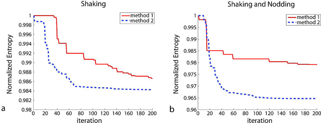
For 192×192×96 resolution, computation time per iteration was around 35 seconds. Figure 9 shows the value of the cost function (i.e. entropy) as a function of the iteration number. Figure 9a show the iterations for the experiment given in Fig. 4, and Fig. 9b show the iterations for the experiment given in Fig. 6. For both cases, the convergence of method 2 was faster than that of method 1. For the case with shaking motion, both algorithms yielded adequate image quality in 200 iterations (Fig. 9a, Table 1, subject 1). However, for the case with mixed shaking and nodding motion, it was observed that method 1 did converge to yield an adequate image quality in 200 iterations (Fig. 9b, Table 1, subject 2). This was due to the high number of segments and, thus, the high number of unknowns (Fig. 6d). The total computation time was around 2 hours for the entire 3D volume and 200 iterations.
Figure 9.
The value of the cost function (i.e. entropy) as a function of the iteration number. (a) The iterations for the experiment given in Fig. 4 (subject 1) and (b) Fig. 6 (subject 2) are shown. For the case with multiple in-plane rotations, the convergence of method 2 was faster than method 1 (a) due to the lower number of unknowns. For the case with more complicated motion where the subject performed both shaking and nodding, it was observed that the segmentation based autofocusing did not converge during 200 iterations to yield adequate image quality (b). This was due to the high number of segments, and thus, the high number of unknowns (Fig. 6d). However, cross-calibration matrix based autofocusing had a fast convergence rate in this case. Given 200 iterations, the total computation time was around 2 hours.
4. Discussion
In this study, monovision-based prospective motion correction was combined with retrospective entropy-based autofocusing to remove residual motion-related errors in the images. For the in-vivo experiments, the residual errors were caused by the inaccurate cross-calibration between the scanner and camera reference frames. Thus, prospective correction left behind residual artifacts in the images (Figs. 4c, 5c, 6c, 8c). In order to simulate cross-calibration errors, the initial cross-calibration scan was skipped and cross-calibration information was used from a different subject. The cross-calibration matrix was different between different subjects because the camera position needed to be adjusted to account for different head shapes of the subjects. In general, retrospective correction using ‘cross-calibration matrix-based’ autofocusing (method 2) performed better compared to ‘segmentation-based’ autofocusing (method 1). This was shown in Table 1 where the AES values for method 2 were higher in general compared to the AES values for method 1 and the number of failures for method 1 (7/11) was higher compared to that of method 2 (0/11). This had two reasons: First, for all cases in Table 1, the number of unknowns to be determined was larger for method 1 (=(#segments-1)×6) compared to method 2 (=6). An increase in the number of unknowns decreases the speed of convergence and robustness of the optimization algorithm and makes it more probable for the iteration to get stuck in local minima. Despite increasing the maximum allowed number of iterations would potentially increase the image quality for method 1, this wasn’t applied in this study due to the impractical reconstruction times for very high number of iterations. Secondly, for method 1, it was assumed that there is negligible motion within the segments. However, depending on the error in cross-calibration and the segmentation threshold chosen, this assumption may not always be satisfied. In this case, the residual motion within the segments can be significant enough to effect the iterations in the optimization algorithm. For this study, this segmentation threshold (3° rotation, 3 mm translation) was empirically determined. Note that this threshold was applied to the tracking data from the camera; the actual range of motion between k-space lines inside the same segment was much less than this threshold since the data was prospectively corrected up to a certain degree. However, the degree to which motion was prospectively corrected still depended on the error in the cross-calibration, which could affect the convergence of method 1. Apart from the robustness of optimization discussed above, the selection of this threshold depends on many other factors (maximum artifact level to be tolerated, acquisition resolution, etc.) and will be the focus of future studies.
It was also shown for subject 2 that the motion estimates obtained after retrospective autofocusing (using method 2) were very similar to the actual motion pattern that was obtained with the true cross-calibration matrix, demonstrating the accuracy of retrospective correction (Fig. 7).
In general, method 2 can be expected to be more robust and faster compared to method 1 due to the smaller number of unknowns of method 2 and due to the residual motion within segments for method 1. However, it must be noted that method 2 assumes that the residual error in the k-space data is caused only by the miscalibration of the system. That is, any inaccuracy coming from the inaccuracies in the pose detection cannot be accounted for. On the other hand, method 1 divides the k-space into segments and corrects for any arbitrary residual motion between these segments. Thus, this method can potentially correct for errors originating from any imperfection in the system, including both inaccurate cross-calibration and optical pose detection errors.
One of the disadvantages of applying retrospective autofocusing to 3D data is the long post-processing times. It was shown that, using 200 iterations, the processing times were around 2 hours for this dataset. Since most of the postprocessing is dominated by the 3D gridding algorithm, we believe it is possible to speed up each iteration using more efficient algorithms, or even graphical processing units (GPUs) (24).
We demonstrated the application of our hybrid approach to perform optical prospective motion correction when the geometric relation between the ‘camera reference frame’ and the ‘MR scanner reference frame’ (i.e. cross-calibration) is on error. In general, for our motion correction experiments, which are done in a controlled setting, the cross-calibration is determined with high enough accuracy to yield adequate image quality (9,10). However, in a clinical setting, cross-calibration can be on error due to unintended cross-calibration errors. On the other hand, it can be desirable to skip cross-calibration step entirely and use a pre-determined approximate cross-calibration matrix in order to assure patient convenience with very little scan overhead. To increase robustness of prospective motion correction and mitigate cross-calibration error, the aim of this study was to combine prospective optical motion correction with retrospective autofocusing. The hybrid approach described in this study has three important applications:
Retrospective autofocusing can be used as a fallback mechanism in case the ‘scanner reference frame’ and ‘camera reference frame’ was miscalibrated. Miscalibration might happen due to distortions in the calibration scan that can be caused by gradient non-linearities, or inaccuracies of patient table positioning.
Retrospective autofocusing can be used to perform prospective correction without a cross-calibration phase. In this case, an “approximate” cross-calibration can be used for all exams and the residual errors can be corrected retrospectively. This was the case for the in-vivo experiments in this study. Given that the cross-calibration and prospective motion correction is accurate up to a certain degree, the spin history effects can be expected to be negligible. A certain degree of accuracy is still expected from the prospective correction in order to minimize undersampling artifacts and spin history effects in slice selective acquisitions. If the camera is placed approximately at the same location for different exams, this can readily be satisfied in most situations.
Retrospective autofocusing can be used to correct for motion artifacts in the calibration scan itself. This was demonstrated in Fig. 8 where a high-resolution scan was performed to extract the agar droplets attached to the marker. The subject was instructed to perform head shaking to simulate a case where there is patient motion during the calibration scan. In this experiment, without prospective correction, the agar droplets were unidentifiable (Fig. 8f). With prospective correction, the image quality was still inadequate because the true cross-calibration was unknown (Fig. 8g). After retrospective correction, the agar droplets were clearly distinguishable (Fig 8h).
An important property of the segmentation-based autofocusing (i.e., method 1) is that, for a subject lying still during the examination, the whole k-space data will be populated inside a single segment (Fig. 2). This would mean that the initial image would be maintained. Likewise, for the cross-calibration matrix-based autofocusing (method 2), if the detected motion Tsi→s0 is unity, regardless of the value of the correction term T(cor), the motion update to be applied to the k-space data will also be unity (Eq. 8). This implies that for a “good” data in which there is no patient motion, the image quality won’t be degraded by the application of retrospective correction.
An important requirement for the proposed method is that the residual error on the data does not cause significant undersampling artifacts and spin history effects (for 2D slice-selective acquisitions). This requires that the cross-calibration matrix is accurate up to a certain degree, which can be ensured by performing an off-line calibration using a phantom. A good estimate for the initial cross-calibration matrix is also needed to ensure that, for method 1, the residual motion within each segment is not large. Having a good estimate of cross-calibration allows for correction of stronger head motions. On the other hand, if the residual error on the data can be kept low enough, the retrospective correction proposed in this manuscript can even be applied to 2D slice-selective sequences. However, applicability of the hybrid approach to 2D sequences requires further investigation.
Previously, hybrid approaches that use both prospective and retrospective correction have been proposed. In these combined approaches, retrospective correction was used to remove residual error on the prospectively corrected data, allowing one to benefit from the advantages of both schemes. In one such approach, a Kalman filter was used successively to remove the noise on the tracking data coming from a stereovision tracking system (14). The corrected tracking data was then used to realign k-space lines to enhance image quality. In another application, motion-induced B0-inhomogeneity changes were corrected retrospectively based on the susceptibility distribution of the object (13). Compared to the first approach, which improves the precision of the system, our method was aimed at improving the accuracy of tracking. In general, precision can be improved using a smoothing filter (e.g. Kalman filter), which is a method common to most systems. However, in order to improve accuracy, the underlying mechanisms that cause the inaccuracies have to be determined and modeled properly. This was the common point between the method described here and in (13), where susceptibility model of the object was used to reduce geometric distortions.
One possible improvement to our method can be achieved by altering the optimization routine. In this study, we used the simplex algorithm, which was implemented by the fminsearch function in MATLAB, which had poor convergence on 7 of the 11 cases for method 1 (for method 2, the convergence of simplex method was robust for all our experiments). We also tried method 1 with the fminunc function in MATLAB that uses the BFGS Quasi-Newton method on subjects 2 and 6 with, but no improvement in convergence was observed. It is also possible to fine-tune the simplex optimization algorithm by changing the initial guess, initial simplex scale and the tolerance of the cost function or the unknown variables. Alternative optimization routines or fine-tuning of the current optimization routine was not thoroughly investigated in this study and provides room for possible improvement.
Another important aspect of the proposed method is the choice of cost function. In this study, entropy was chosen as the cost function due to its auto-correction capabilities without requiring data redundancy. Entropy has been used successfully to remove blurring and ghosting in motion-corrupted images (15) and for ghost correction in echo-planar imaging (25). However, other options for the cost function, such as ghost energy, should not be overlooked.
One challenge that remains is the correction of altered effective coil sensitivity as a result of motion. This correction can be especially important for our iterative optimization as inaccurate coil sensitivity information can alter the convergence of iterative optimization. Correction for coil sensitivities can be performed using the method described in (11), but was not applied in this study.
It is worth noting that, for both methods 1 and 2, the existence of the optical tracking system reduces the dimensionality of the 3D retrospective autofocusing problem, making autofocusing applicable to a 3D acquisition. For method 1, the dimensionality of the autofocusing problem is reduced to (#segments-1) × 6 whereas for method 2, it is reduced to 6. Without the motion tracking system, the dimensionality would be (#k-space lines-1) ×6, which would be impractical to solve.
Conclusion
Optical prospective motion correction was combined with retrospective autofocusing to establish a robust rigid head motion correction method. Retrospective autofocusing was used to remove residual errors in the prospectively corrected image that arose from inaccurate scanner-camera cross-calibration. Prospective correction reduced the number of unknowns to be solved for via retrospective autofocusing, making retrospective autofocusing feasible for 3D imaging. In the case when cross-calibration errors were introduced to the system, image quality was improved after retrospective correction for in vivo experiments.
Acknowledgements
We would like to thank Rafael O’Halloran for the hand drawings used in this manuscript. We would also like to thank Samantha Holdsworth, Stefan Skare, Heiko Schmiedeskamp and Melvyn Ooi for helpful discussions, and Daniel Kopeinigg for helping with the data acquisition. The authors are also grateful to Intel, specifically to Greg Wagnon and Markus Weingartner, for providing the Nehalem servers and help with the computer infrastructure.
Footnotes
This work was presented in part at the: Joint Annual Meeting of the ISMRM & ESMRMB, Stockholm, Sweden, 2010
References
- 1.Thesen S, Heid O, Mueller E, Schad LR. Prospective acquisition correction for head motion with image-based tracking for real-time fMRI. Magn Reson Med. 2000;44(3):457–465. doi: 10.1002/1522-2594(200009)44:3<457::aid-mrm17>3.0.co;2-r. [DOI] [PubMed] [Google Scholar]
- 2.van der Kouwe AJ, Benner T, Dale AM. Real-time rigid body motion correction and shimming using cloverleaf navigators. Magn Reson Med. 2006;56(5):1019–1032. doi: 10.1002/mrm.21038. [DOI] [PubMed] [Google Scholar]
- 3.Ooi MB, Krueger S, Thomas WJ, Swaminathan SV, Brown TR. Prospective real-time correction for arbitrary head motion using active markers. Magn Reson Med. 2009;62(4):943–954. doi: 10.1002/mrm.22082. [DOI] [PMC free article] [PubMed] [Google Scholar]
- 4.Dold C, Zaitsev M, Speck O, Firle EA, Hennig J, Sakas G. Prospective head motion compensation for MRI by updating the gradients and radio frequency during data acquisition. Med Image Comput Comput Assist Interv. 2005;8(Pt 1):482–489. doi: 10.1007/11566465_60. [DOI] [PubMed] [Google Scholar]
- 5.Dold C, Zaitsev M, Speck O, Firle EA, Hennig J, Sakas G. Advantages and limitations of prospective head motion compensation for MRI using an optical motion tracking device. Acad Radiol. 2006;13(9):1093–1103. doi: 10.1016/j.acra.2006.05.010. [DOI] [PubMed] [Google Scholar]
- 6.Zaitsev M, Dold C, Sakas G, Hennig J, Speck O. Magnetic resonance imaging of freely moving objects: prospective real-time motion correction using an external optical motion tracking system. Neuroimage. 2006;31(3):1038–1050. doi: 10.1016/j.neuroimage.2006.01.039. [DOI] [PubMed] [Google Scholar]
- 7.Qin L, van Gelderen P, Derbyshire JA, Jin F, Lee J, de Zwart JA, Tao Y, Duyn JH. Prospective head-movement correction for high-resolution MRI using an in-bore optical tracking system. Magn Reson Med. 2009;62(4):924–934. doi: 10.1002/mrm.22076. [DOI] [PMC free article] [PubMed] [Google Scholar]
- 8.Armstrong B, Andrews-Shigaki B, Barrows R, Kusik T, Ernst T, Speck O. Performance of stereo vision and retro-grate reflector motion tracking systems in the space constraints of an MR scanner. Proceedings of the 17th Annual Meeting of ISMRM; Honolulu, HI. 2009. p. 4641. [Google Scholar]
- 9.Aksoy M, Forman C, Straka M, Skare S, Holdsworth S, Hornegger J, Bammer R. Real time optical motion correction for diffusion tensor imaging. Magnetic Resonance in Medicine. doi: 10.1002/mrm.22787. [DOI] [PMC free article] [PubMed] [Google Scholar]
- 10.Forman C, Aksoy M, Hornegger J, Bammer R. Self-encoded marker for optical prospective head motion correction in MRI. Med Image Comput Comput Assist Interv. 2010;13(Pt 1):259–266. doi: 10.1007/978-3-642-15705-9_32. [DOI] [PubMed] [Google Scholar]
- 11.Bammer R, Aksoy M, Liu C. Augmented generalized SENSE reconstruction to correct for rigid body motion. Magn Reson Med. 2007;57(1):90–102. doi: 10.1002/mrm.21106. [DOI] [PMC free article] [PubMed] [Google Scholar]
- 12.Aksoy M, Liu C, Moseley ME, Bammer R. Single-step nonlinear diffusion tensor estimation in the presence of microscopic and macroscopic motion. Magn Reson Med. 2008;59(5):1138–1150. doi: 10.1002/mrm.21558. [DOI] [PMC free article] [PubMed] [Google Scholar]
- 13.Boegle R, Maclaren J, Zaitsev M. Combining prospective motion correction and distortion correction for EPI: towards a comprehensive correction of motion and susceptibility-induced artifacts. MAGMA. 2010;23(4):263–273. doi: 10.1007/s10334-010-0225-8. [DOI] [PubMed] [Google Scholar]
- 14.Maclaren J, Lee KJ, Luengviriya C, Speck O, Zaitsev M. Combined prospective and retrospective motion correction to relax navigator requirements. Magnetic Resonance in Medicine. doi: 10.1002/mrm.22754. [DOI] [PubMed] [Google Scholar]
- 15.Atkinson D, Hill DL, Stoyle PN, Summers PE, Keevil SF. Automatic correction of motion artifacts in magnetic resonance images using an entropy focus criterion. IEEE Trans Med Imaging. 1997;16(6):903–910. doi: 10.1109/42.650886. [DOI] [PubMed] [Google Scholar]
- 16.Atkinson D, Hill DL, Stoyle PN, Summers PE, Clare S, Bowtell R, Keevil SF. Automatic compensation of motion artifacts in MRI. Magn Reson Med. 1999;41(1):163–170. doi: 10.1002/(sici)1522-2594(199901)41:1<163::aid-mrm23>3.0.co;2-9. [DOI] [PubMed] [Google Scholar]
- 17.Hartley R, Zisserman A. Multiple view geometry in computer vision. Cambridge: Cambridge University Press; 2003. [Google Scholar]
- 18.Pipe JG. Motion correction with PROPELLER MRI: application to head motion and free-breathing cardiac imaging. Magn Reson Med. 1999;42(5):963–969. doi: 10.1002/(sici)1522-2594(199911)42:5<963::aid-mrm17>3.0.co;2-l. [DOI] [PubMed] [Google Scholar]
- 19.Manduca A, McGee K, Welch E, Felmlee J, Grimm R, Ehman R. Autocorrection in MR Imaging: Adaptive Motion Correction without Navigator Echoes1. Radiology. 2000;215(3):904. doi: 10.1148/radiology.215.3.r00jn19904. [DOI] [PubMed] [Google Scholar]
- 20.Nelder J, Mead R. A simplex method for function minimization. The computer journal. 1965;7(4):308. [Google Scholar]
- 21.Jackson JI, Meyer CH, Nishimura DG, Macovski A. Selection of a convolution function for Fourier inversion using gridding. IEEE Trans Med Imaging. 1991;10(3):473–478. doi: 10.1109/42.97598. [DOI] [PubMed] [Google Scholar]
- 22.Beatty PJ, Nishimura DG, Pauly JM. Rapid gridding reconstruction with a minimal oversampling ratio. IEEE Trans Med Imaging. 2005;24(6):799–808. doi: 10.1109/TMI.2005.848376. [DOI] [PubMed] [Google Scholar]
- 23.Canny J. A computational approach to edge detection. Readings in computer vision: issues, problems, principles, and paradigms. 1987;184:87–116. [Google Scholar]
- 24.Stone SS, Haldar JP, Tsao SC, Hwu WMW, Sutton BP, Liang ZP. Accelerating advanced MRI reconstructions on GPUs. J Parallel Distr Com. 2008;68(10):1307–1318. doi: 10.1016/j.jpdc.2008.05.013. [DOI] [PMC free article] [PubMed] [Google Scholar]
- 25.Clare S. Iterative Nyquist ghost correction for single and multi-shot EPI using an entropy measure. Proceedings of the 16th Annual Meeting of ISMRM; Toronto, Canada. 2003. p. 1041. [Google Scholar]


