Abstract
Understanding the basic physics of ultrasound is essential for acute care physicians. Medical ultrasound machines generate and receive ultrasound waves. Brightness mode (B mode) is the basic mode that is usually used. Ultrasound waves are emitted from piezoelectric crystals of the ultrasound transducer. Depending on the acoustic impedance of different materials, which depends on their density, different grades of white and black images are produced. There are different methods that can control the quality of ultrasound waves including timing of ultrasound wave emission, frequency of waves, and size and curvature of the surface of the transducer. The received ultrasound signal can be amplified by increasing the gain. The operator should know sonographic artifacts which may distort the studied structures or even show unreal ones. The most common artifacts include shadow and enhancement artifacts, edge artifact, mirror artifact and reverberation artifact.
Keywords: Artifacts, physics, ultrasound, waves
INTRODUCTION
Understanding the basic physics of ultrasound is essential for acute care physicians who perform point-of-care ultrasound to make accurate critical decisions. Ultrasound is made up of mechanical waves that can transmit through different materials like fluids, soft tissues and solids. It has a frequency higher than the upper human auditory limit of 20 KHz.[1] Ultrasound frequency is defined as the number of ultrasound waves per second, and medical ultrasound machines use waves with a frequency ranging between 2 and 15 MHz.[2] The velocity of ultrasound in a specific medium equals the frequency of ultrasound multiplied by its wave length.[1]
BASIC PHYSICS
Medical ultrasound machines generate ultrasound waves and receive the reflected echoes. Brightness mode (B mode) is the basic mode that is usually used.[2] The B mode gives a two dimensional (2D) black and white image that depends on the anatomical site of the slice. The body can be imaged in different planes depending on the position of the probe. These thin slices are of less than 1 mm each and can be sagittal, coronal, transverse, or oblique. Sound waves are emitted from piezoelectric crystals from the ultrasound transducer. Piezoelectric crystals are fabricated from material that changes electrical signals to mechanical vibrations and changes mechanical vibrations to electrical signals.[2] As ultrasound waves pass through various body tissues, they are reflected back to the transducer creating an image on the ultrasound screen.[3] Acoustic impedance is defined as the resistance for propagation of ultrasound waves. This varies according to the density of the material ultrasound passes through. When the material is more solid, then the particles are denser and sonongraphic waves will reflect more [Figure 1].[4] Fluid transmits more sound waves than solid material. So less ultrasound waves will reflect back from fluids. This produces an an echogenic “black” image. Stones and bones reflect more sound waves than fluid and produce “white” bright images. Since ultrasound waves cannot transmit through stones, a black acoustic shadow will be present behind them. Air is a strong ultrasound beam reflector making it difficult to visualize structures behind it.[5]
Figure 1.
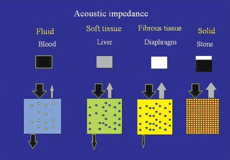
The denser a material is the more it reflects the sonographic waves. Fluid (like blood) transmits ultrasound waves and have minimum waves reflected back. This yields a black “an echogenic” image. Stones yield white images with a shadow behind them. Soft tissues (like the liver) yield different grey colour scales
CONTROLLING ULTRASOUND WAVES
There are different methods that control the way ultrasound waves are emitted from the ultrasound transducers. Emission of ultrasound waves can be either interrupted or continuous. Interrupted emission of ultrasound waves generates brightness (B) mode images while continuous emission generates Doppler mode. Imaging one line over time is called the moving mode (M Mode).[4] Changing the frequency of ultrasound waves will control the penetration and resolution of the images. The higher the frequency, the better is the resolution, however the depth of penetration decreases. The opposite will happen when using lower frequency transducers. Longer distances and higher frequencies result in greater attenuation.[2] This implies that for obese patients and deep structures, probes of low frequencies should be used while probes of high frequency should be used for superficial structures.[2] The received ultrasound signal can be amplified by increasing the gain. Decreased gain yields a black image and details are masked, while increased gain yields a whiter image.[6] Time gain compensation will change the gain factor so that equally reflective structures will be displayed with the same brightness regardless of their depth.[2]
Ultrasound waves are emitted perpendicular to the surface of the transducer. It is possible to widen the deep sonographic field by bending the surface of the transducer (convex array transducer) [Figure 2]. Waves will be parallel to each other when the probe surface is flat (linear array transducer). Linear array transducers usually have high frequencies (10-12 MHz), less penetration, and excellent resolution. The ultrasound images obtained by a linear array transducer will be rectangular in shape while those obtained by a convex array transducer will be wider with increased depth. Reducing the surface of the transducer and using fan shaped sectors will enable the examiner to visualize thoracic structure between the ribs [Figure 2].[7]
Figure 2.
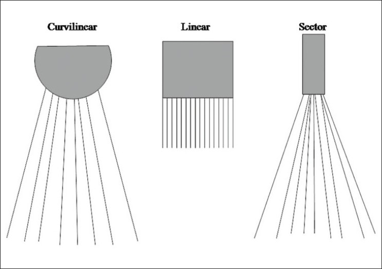
Changing the shape of the surface of the probe and its size gives different types of sectors used for different applications
SONONGRAPHIC ARTIFACTS
The operator should be especially knowledgeable about sonographic artifacts that can mislead him/her. Artifacts may distort the size, position and shape of the studied structures or even show structures that are not present.[5] Some artifacts are very useful for diagnosing different conditions. Ultrasound is unable to transmit through solid structure like the stones or ribs. This causes a shadow artifact behind the solid structures.[8] Shadow artifact is very useful for diagnosing gall stones [Figure 3]. Posterior enhancement artifact may occur when imaging fluid filled structures (like the gall bladder or urinary bladder). More ultrasound waves will penetrate the fluid filled structure, and a white enhancement area will appear behind it [Figure 3].[4] The posterior enhancement will increase the gain behind the urinary bladder, and it is important to reduce the gain when looking for small amounts of pelvic fluid in Pouch of Douglas, otherwise it can be missed. The edge (refraction) artifact occurs when a beam of ultrasound refracts at the edge of a rounded structure like a kidney or urinary bladder. This artifact may disappear when changing the angle of the ultrasound beam clarifying the nature of the artifact.[3]
Figure 3.
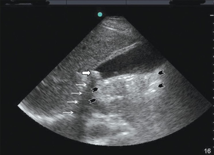
A gall stone at the neck of the gall bladder (white thick arrow) causing a shadow artifact behind it (white thin arrows). The posterior enhancement is shown behind the gall bladder between the black arrow heads
The mirror artifact occurs when the sonographic waves are reflected by an angle by a high acoustic impedance tissue, for example like the diaphragm. The mirror artifact will mimic a virtual object similar to a true mirror on the opposite side of the structure [Figure 4].[8,9] The mirror image is more hypoechoic and somewhat more blurred and distorted than the image of the original structure as a result of absorption the of the ultrasound beam when passing through a long pathway.[5] Reverberation artifact occurs when ultrasound bounces between two interfaces especially with high acoustic impedance like the pleura.[8,9] The waves will move forward and backward between these interfaces. The machine will recognize these waves as parallel lines with equal distances between them, and decreased density for the deeper lines, because the reflected waves become gradually lesser in number. This results in a stripped pattern having alternating dark and clear lines at regular intervals [Figure 5].[6]
Figure 4.
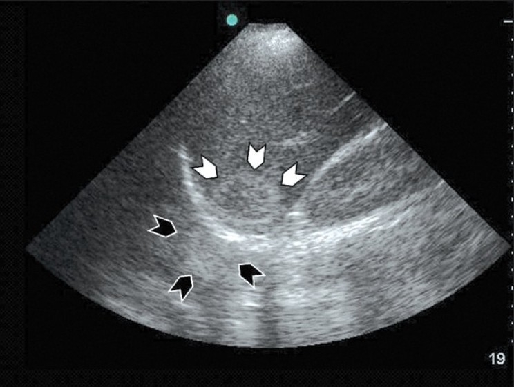
Coronal section of the liver using a curvilinear probe showing a haemangioma under the dome of the diaphragm (white arrow heads) and its mirror artifact above the diaphragm (black arrow heads). Notice that the mirror artifact is more blurred and distorted than the image of the original hemangioma
Figure 5.
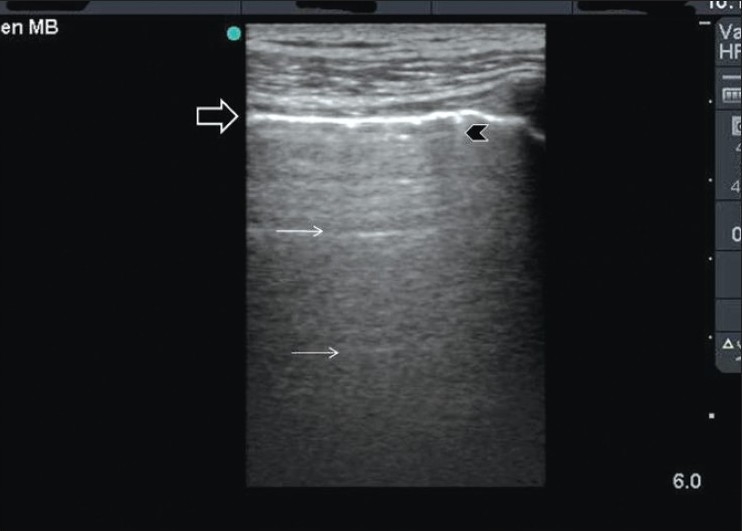
Reverberation artifact of the lung occurs as ultrasound waves bounce between the transducer and the pleura. The pleura is shown as a hyperdense white line (black arrow). The reverberation lines (white arrows) represent repetition of the pleural line. The distance between these lines are equal. A comet tail artifact is also shown (black arrow head)
Footnotes
Source of Support: Nil.
Conflict of Interest: None declared.
REFERENCES
- 1.Wells PN. Physics and bioeffects. In: McGahan JP, Goldberg BB, editors. Diagnostic Ultrasound, A logical approach. Philadelphia: Lppincott-Raven Publishers; 1998. pp. 1–19. [Google Scholar]
- 2.Hangiandreou NJ. AAPM/RSNA physics tutorial for residents.Topics in US: B-mode US: Basic concepts and new technology. Radiographics. 2003;23:1019–33. doi: 10.1148/rg.234035034. [DOI] [PubMed] [Google Scholar]
- 3.Rose JS. Ultrasound physics and knobology. In: Simon BC, Snoey ER, editors. Ultrasound in Emergency and Ambulatory Medicine. St Louis: Mosby-Year book Inc; 1997. pp. 10–38. [Google Scholar]
- 4.Rose JS, Bair AE. Fundamentals of ultrasound. In: Cosby KS, Kendall JL, editors. Practical guide to Emergency Ultrasound. PA: Lippincott Williams and Wilkins; 2006. pp. 27–41. [Google Scholar]
- 5.Schuler A. Image artifacts and pitfalls. In: Mathis G, editor. Chest sonography. 2nd ed. New York: Springer; 2008. pp. 175–82. [Google Scholar]
- 6.Lichtenstein DA. Basic notions in critical ultrasound. In: Lichtenstein DA, editor. Whole body ultrasonongraphy in the critically ill. New York: Springer; 2010. pp. 3–10. [Google Scholar]
- 7.Whittingham TA. Medical diagnostic applications and sources. Prog Biophys Mol Biol. 2007;93:84–110. doi: 10.1016/j.pbiomolbio.2006.07.004. [DOI] [PubMed] [Google Scholar]
- 8.Feldman MK, Katyal S, Blackwood MS. US artifacts. Radiographics. 2009;29:1179–89. doi: 10.1148/rg.294085199. [DOI] [PubMed] [Google Scholar]
- 9.Muglia V, Cooperberg PL. Artifacts. In: McGahan JP, Goldberg BB, editors. Diagnostic Ultrasound, A logical approach. Philadelphia: Lippincott-Raven Publishers; 1998. pp. 21–37. [Google Scholar]


