Abstract
Purpose: Applications of volumetric CT (VCT) are hampered by shading and streaking artifacts in the reconstructed images. These artifacts are mainly due to strong x-ray scatter signals accompanied with the large illumination area within one projection, which lead to CT number inaccuracy, image contrast loss and spatial nonuniformity. Although different scatter correction algorithms have been proposed in literature, a standard solution still remains unclear. Measurement-based methods use a beam blocker to acquire scatter samples. These techniques have unrivaled advantages over other existing algorithms in that they are simple and efficient, and achieve high scatter estimation accuracy without prior knowledge of the imaged object. Nevertheless, primary signal loss is inevitable in the scatter measurement, and multiple scans or moving the beam blocker during data acquisition are typically employed to compensate for the missing primary data. In this paper, we propose a new measurement-based scatter correction algorithm without primary compensation for full-fan VCT. An accurate reconstruction is obtained with one single-scan and a stationary x-ray beam blocker, two seemingly incompatible features which enable simple and efficient scatter correction without increase of scan time or patient dose.
Methods: Based on the CT reconstruction theory, we distribute the blocked data over the projection area where primary signals are considered approximately redundant in a full scan, such that the CT image quality is not degraded even with primary loss. Scatter is then accurately estimated by interpolation and scatter-corrected CT images are obtained using an FDK-based reconstruction algorithm.
Results: The proposed method is evaluated using two phantom studies on a tabletop CBCT system. On the Catphan©600 phantom, our approach reduces the reconstruction error from 207 Hounsfield unit (HU) to 9 HU in the selected region of interest, and improves the image contrast by a factor of 2.0 in the high-contrast regions. On an anthropomorphic head phantom, the reconstruction error is reduced from 97 HU to 6 HU in the soft tissue region and image spatial nonuniformity decreases from 27% to 5% after correction.
Conclusions: Our method inherits the main advantages of measurement-based methods while avoiding their shortcomings. It has the potential to become a practical scatter correction solution widely implementable on different VCT systems.
Keywords: scatter correction, single scan, stationary beam blocker, volumetric CT, cone-beam CT
INTRODUCTION
Over the past two decades, significant changes have been observed in the way CT images are acquired. Commercial CT scanners have advanced from 2 to 320 slices, and the development of larger-area flat-panel x-ray detectors have given rise to volumetric CT (VCT) systems with z-axis extents of 16 cm or greater.1, 2, 3, 4, 5 For example, in current image-guided radiation therapy (IGRT), on-board cone-beam CT (CBCT) is being increasingly implemented for accurate patient positioning and tumor targeting.1, 2, 3 In the coronary artery imaging, the 320-slice multi-detector CT (MDCT) scanner has enabled volumetric imaging of the entire heart free of stair-step artifacts at a single phase within one cardiac cycle.4, 5 However, as the volume of tissue irradiated in one projection increases, so does the scattered radiation that reaches the detector. The strong x-ray scatter signals in the projection images, with scatter-to-primary ratio (SPR) of even a few percent, lead to severely deteriorated qualities of the reconstructed CT images, including CT number inaccuracy, image contrast loss and spatial nonuniformity.6 It has been reported that on a CBCT system, without scatter correction, the SPR is typically around 2 on a midsize volume and can be up to 5 on a human torso.7 The large scatter signals may lead to CT number errors up to 350 HU.8 Scatter contamination has become one fundamental limitation on VCT image quality and scatter correction is one of the first-priority issues on the improvement of VCT imaging performance.
The significance of scatter correction on VCT systems is indicated by the number of publications on this topic.6, 7, 8, 9, 10, 11, 12, 13, 14, 15, 16, 17 These published algorithms can be divided into two major categories based on whether scatter is directly measured or not. The non-measurement-based methods prevent the scatter photons from reaching the detector, or estimate scatter by explicit∕implicit assumptions of the object after a conventional data acquisition. Typical examples include air gap,9 antiscatter grid,10, 11 analytical modeling,12, 13 Monte Carlo (MC) simulation,14, 15 and modulation methods.16, 17 These methods improve the image quality to a certain extent with different drawbacks in practical implementations. Air gap or antiscatter grid methods are often insufficient by themselves and require increased dose to the patient to maintain an appropriate signal-to-noise ratio (SNR) in the projection images.18 Analytical modeling methods require an accurate scatter model and scatter estimation performance may be reduced especially for heterogeneous and complex objects. MC modeling can generate accurate scatter estimates but is computationally intense. This technique is usually combined with analytical methods for efficient practical implementations.14 The modulation method corrects for scatter signals based on the difference between the primary and scatter response functions to a primary modulator inserted between the source and the imaged object,16 and optimization of the method is still in progress.7, 19
Due to the complexity of the interaction between photons and the object, direct scatter measurements typically obtain more accurate scatter estimates when the imaged object has a complicated geometry. The measurement-based methods typically insert sparse x-ray beam blockers (e.g., lead) between the x-ray source and the object, and obtain scatter samples inside the resultant shadows on the detector.8, 20, 21, 22, 23 The scatter distribution of the whole-field is then accurately estimated using interpolation∕extrapolation on the sampled scatter data since scatter distributions have dominant low-frequency components.8, 24 These methods are simple and efficient, and achieve effective scatter correction without prior knowledge of the imaged object. Nevertheless, primary signal loss is inevitable for the purpose of scatter measurement. Currently, it is generally believed that the missing primary data in the measurement-based scatter correction methods have to be compensated for to achieve an accurate CT image reconstruction. As such, unconventional imaging schemes are commonly employed, such as performing two CT scans on the same object, one with the blocker in place and one without, or moving the blocker during one scan.8, 25, 26 The two-scan method increases scan time and patient dose, and the reconstruction accuracy is susceptible to the patient motion between the two scans. The moving-blocker method complicates the data acquisition process, and the blocker motion introduces new challenges for accurate CT reconstruction.
A practical scatter correction method in clinical applications should be simple, dose efficient, effective and readily implementable on different x-ray imaging systems. Among different approaches reviewed above, the measurement-based methods have many of the desired properties of a clinically practical scatter correction solution, except that the compensation for the primary data loss makes the method unfavorable. In this paper, we propose a new measurement-based scatter correction method without primary compensation. Specifically, the method achieves effective scatter correction and accurate reconstruction with one single full scan and a stationary x-ray beam blocker, two seemingly incompatible features that enable simple and efficient scatter correction without increase of scan time or patient dose. The same imaging geometry as that in the conventional scatter measurement is employed, in which the radio-opaque x-ray beam blocker is inserted between the x-ray source and the imaged object. Based on the CT reconstruction theory, we distribute the blocked areas over one projection where primary signals are considered to be approximately redundant in a full scan. The CT image quality is therefore not degraded even with primary signal loss, and the compensation for missing primary signals is unnecessary. Scatter is then accurately estimated by interpolation on the scatter samples behind the blocker shadows and scatter-corrected CT images are obtained using a modified FDK algorithm.27
In this work, we investigate the proposed method for its implementations on a CBCT system in current radiation therapy. Two phantom studies have been carried out on our CBCT tabletop system. To ensure a valid data redundancy condition for scatter measurement, we implement our method in a full-fan CT scan (i.e., with a 360-degree rotation and nonoffset detector geometry). An evaluation phantom, Catphan©600, is used in the first study, and a detailed quantitative image analysis is carried out on the phantom inserts. The second study uses an anthropomorphic head phantom with a bowtie filter to match the configuration of a clinical system. The scatter correction is more challenging on the head phantom due to the object heterogeneity.
METHOD
Scatter correction using a single-scan and a stationary beam blocker
General guidelines of blocker design in a full CT scan
In a full CT scan, one projection line through the object may be measured multiple times. If noise and measurement errors are not considered, we can block some of these redundant rays without degrading the reconstructed CT image quality as long as the projection rays are measured at least once. This makes it possible to allocate areas in the projection space, where primary data are redundant, solely for scatter measurement using a conventional x-ray beam blocker. No compensation for the missing primary data is necessary and the data acquisition is complete with one single-scan.
Based on the key idea presented above, we have the following guidelines for the beam blocker design. (1) The blocked area should be almost uniformly distributed across the projection field, such that whole-field scatter distributions can be estimated using interpolation. (2) The blocked primary signals should only contain redundant rays. (3) The blocking of the projection data should not significantly complicate the reconstruction algorithm or degrade the reconstruction accuracy. These blocker design guidelines are applicable for different x-ray VCT systems with different scanning trajectories. Note that, in circular CT scans, redundant rays can be found only on the plane of the source trajectory (midplane). On CT systems with a relatively small cone angle, we adopt an approximation of redundancy on any two rays whose projections onto the midplane are identical. For on-board CBCT systems in radiation therapy that we investigate in this paper, the proposed method further requires a non-shifted detector and a full scan with a 360-degree rotation.
X-ray beam blocker in the proposed scatter correction method
The blocker design in our scatter correction is inspired by the half-fan scan mode available on commercial on-board CBCT systems (e.g., Varian Trilogy radiation therapy machines).12 In a half-fan scan, the flat-panel detector is shifted laterally, which is equivalent to stationary blocking of half of the detector. One projection line is measured at least once from opposing directions in a full rotation and accurate reconstruction is still achievable. As the detector moves toward the periphery of the imaged object, the field of view (FOV) of the imaging system is therefore significantly enlarged without increasing the physical size of the detector.
If the half-fan geometry is achieved by using a beam blocker on half of the illumination area, instead of shifting the detector, it can be seen that this blocker design satisfies the last two of the three requirements of a desired blocker. However, the blocked area is not distributed across the projection view, and a whole-field scatter estimate therefore cannot be accurately obtained from the measured scatter signals. To obtain uniformly distributed scatter samples, one solution is to shift the blocking in the horizontal direction for different vertical slices on the detector.
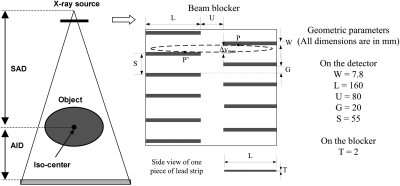
Figure 1 shows the geometry of the CBCT scanner and the blocker used in the proposed scatter correction method with a “crossing-finger” shape. Each half of the detector is sparsely blocked in the vertical direction by horizontal strips. The strips are vertically shifted for the left and right sides, such that more than half of each horizontal line on the detector is measured. After the insertion of the blocker, the shadows with the same pattern appear on the detector. Note that, reconstruction from the blocked horizontal lines can be obtained accurately in a similar way as in a half-fan reconstruction due to the same half-blocking pattern. As shown in a later section, the blocked projection data are used for two separate half-fan reconstructions. These two half-fan images are then combined to generate the final reconstruction.
Figure 1.
Geometry of the “crossing-finger” x-ray beam blocker used in the proposed method for a circular CBCT scanner. The projection of one point inside the imaged object onto the detector has an elliptical trajectory for a full scan, shown as the dashed circle.
The blocker geometry is specified by several parameters as labeled in Fig. 1. The strip thickness (T) should be large enough to attenuate all the primary signals. In this study, we use lead as the blocker material, and the thickness of the blocker is 2 mm. The optimal values of other geometrical parameters depend on the magnification factor from the inserted blocker to the detector. The scatter estimation accuracy is determined by the pattern of scatter samples on the detector. For simplicity, hereafter in the paper, we use the geometry of the blocker shadow on the detector to describe the blocker geometry. The strip width (W) should be small to avoid too much primary data loss that may lead to inaccurate reconstruction as discussed in details later. However, the finite values of the x-ray focus spot size and the blocker thickness lead to penumbra effects on the scatter signals inside the blocker shadows, which limit the minimum strip width for accurate scatter measurement. In studies presented in this paper, W is about 20 pixels (∼7.8 mm) on the detector. The ramp-filtering step in a filtered-backprojection algorithm may generate large errors around the blocker edges on the detector,28 even if the projection data are complete in a full scan.29 Similar to that in a half-fan scan, the central area of the detector (with U≈ 80 mm on the detector) is left open to alleviate this problem. For a flat-panel detector with a size of 400-by-300 mm2, the length (L) of the strip is 160 mm on the detector.
Our scatter correction method is based on the data redundancy in a CT scan, i.e., one projection line may be measured twice from two opposing directions. These two redundant projection rays are referred to as one “conjugate ray pair” in literature.28, 30 In a circular CBCT scan, the redundancy does not strictly hold for rays passing through the off-planes. However, it is a common practice (e.g., in a half-fan reconstruction) to approximate two rays as redundant under the condition that their projections onto the midplane compose a conjugate ray pair.27 In our blocker design, we implicitly adopt the same approximation. For simplicity of description, in this paper, we refer to the two approximately redundant rays as one conjugate ray pair, no matter whether they are in the midplane.
The redundancy approximation leads to special care in choosing the strip gap (G) of the blocker. The projection trajectory on the detector passing through one object voxel on an off-plane is elliptical as shown in Fig. 1. The measured redundant rays are distributed on this trajectory (e.g., P and P’), and may be both blocked by the strips, resulting in large reconstruction errors. An optimal G should balance between scatter estimation error (a small G is preferred) and primary data loss (a large G is preferred). In our study, we have constructed blockers with different G values and compared the reconstructed images as shown in a later section. G ≈ 20 mm is empirically chosen as the optimal value, which leads to a sampling period (S) of about 55 mm on the detector. As shown in the published literature, this sampling period guarantees accurate scatter estimation.31
The geometrical parameters of the designed blocker are summarized on the right side of Fig. 1.
Scatter estimation and correction
Inside the strip shadows on the detector, primary signals are totally attenuated and only scatter samples are measured. As shown in our previous study, the insertion of the lead strips does not greatly perturb the spatial frequency spectrum of the scatter distributions in the cone-beam projections and scatter still contains dominant low-frequency components.8 The scatter distributions are therefore accurately estimated for the whole field using two-dimensional (2D) interpolation on the measured samples. To avoid the penumbra effect of the strips, only the measured data inside the central one-third of the strip shadows are used in the scatter estimation. These scatter data are first averaged in the longitudinal direction to reduce the noise in the measurement. The averaged scatter data are considered to be located at the centers of the strip shadows. A local-regression low-pass filter with a width of 45 detector pixels (17.5 mm on the detector) is then applied in the lateral direction to further smooth the scatter measurement. The parameters of the smoothing filters are empirically chosen in this study. A cubic spline interpolation∕extrapolation is carried out first in the longitudinal direction, and then in the lateral direction to estimate the scatter distribution of the whole detector area. The estimated scatter data are finally subtracted from the raw projections to generate the scatter-corrected CBCT projections. Note that, other standard smoothing functions and interpolation techniques can also be implemented in the proposed approach.
Reconstruction algorithm design
Although the proposed blocker design complies with the first two requirements of the desired blocker design listed in Sec. 2A1, the missing primary data distributed across the detector post a new challenge for efficient and accurate reconstruction.
In a half-fan scan, due to the offset of the detector, the primary data are approximately redundant only on the central columns. In the commercial reconstruction software, the projections are first multiplied by a preweighting function to compensate for the data redundancy, and a standard FDK reconstruction is then applied on the weighted projections. The preweighting function needs to be smooth in the horizontal direction to avoid numerical errors in the ramp-filtering step of reconstruction, and the sum of the weights on redundant rays should equal one. One practical preweighting function is shown in Eq. 1 as an example
| (1) |
where u and v are the coordinates on the detector as defined earlier, and U is the horizontal length of central redundant columns. In this paper, we define the positive u direction as the right side on the detector. The preweighting function in Eq. 1 is used when the projections are blocked on the right side.
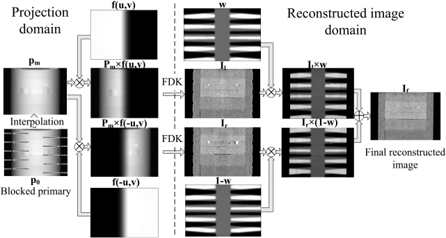
After the insertion of the “crossing-finger” beam blocker, the horizontal lines on the detector have an approximate redundancy pattern similar to that in a half-fan scan, except that the blocking is horizontally shifted at different vertical positions. We therefore design an FDK-based reconstruction algorithm for the proposed approach as a simple extension from the conventional half-fan reconstruction. From the projection data with the blocker in place, assuming that the projection is completely blocked on the left side or on the right side, we use the conventional half-fan reconstruction to separately generate two first-pass CT images, referred to as right and left half-fan CT images, respectively. The left (right) half-fan CT image has poor quality only at the axial slices whose projection onto the detector is blocked on the left (right) side. Since the left and right side blocking strips shift their positions in the vertical direction, a CT volume with high quality for all vertical slices can be obtained by combining the two half-fan CT images.
To quantify the image quality of the left (right) half-fan image, we calculate an intermediate function wl (wr) with the same volume size of the half-fan image, which has a voxel value of one if any projection ray passing through the voxel is not blocked by the left (right) beam blocker strips, and zero otherwise. The calculation of wl and wr can be implemented efficiently in the backprojection step of the FDK reconstruction. Note that wl and wr are not exactly complementary to each other. A smoothed weighting function w is then calculated as:
| (2) |
where the factor (1-wl·wr∕2) sets values of 0.5 to the region where both wl and wr are equal to one, LPF[•] denotes a low-pass filtering to smooth the sharp edges of the weighting function and to make the final image combination seamless. In our implementation, a 2D averaging filter, with a width of 11-by-11 pixels (5.5-by-5.5 mm), is applied on each slice of the volume.
The final image combination is done via the following equation:
| (3) |
where If is the final merged image, Il and Ir are the left and right half-fan CT images, respectively.
The proposed reconstruction is summarized as the following steps and illustrated in Fig. 2:
-
(1)
After scatter correction, generate line integral projection images, pm, via interpolation on the blocked primary, p0.
-
(2)
Reconstruct the left half-fan image, Il, using a conventional half-fan reconstruction algorithm with the preweighting function, f(u,v), given in Eq. 1. Reconstruct the right half-fan image, Ir, similarly with the preweighting function flipped in the horizontal direction, f(-u,v).
-
(3)
Generate the image weighting function w using Eq. 2 and its complement 1-w.
-
(4)
Obtain the final merged image, If, using Eq. 3.
Figure 2.
Workflow of the FDK-based reconstruction with the insertion of the “crossing-finger” blocker.
Evaluation
The lead sheet of the proposed “crossing-finger” blocker was first shaped using a waterjet cutting system. The 2-mm-thick “lead finger” has an x-ray attenuation of over 99.99%, which blocks nearly all the primary photons. To improve the mechanical strength of the blocker, the lead was sandwiched between two layers of thin steel (∼0.2 mm) with the same “crossing-finger” shape using J-B WELD epoxy adhesive (Grainger Corp.).
The proposed method was evaluated using phantom studies on our tabletop CBCT system at Georgia Institute of Technology. The geometry of this system exactly matches that of a Varian On-Board Imager (OBI) CBCT system on the Trilogy radiation therapy machine. Side-by-side image comparisons were carried out on the images without scatter correction and with scatter-corrected using our method. For a quantitative evaluation of the method performance, reconstructed images were also obtained using a narrowly opened collimator (a width of ∼10 mm on the detector). In this fan-beam equivalent geometry, scatter signals were inherently suppressed and the resulting images were used as “scatter-free” reference images in the comparisons (referred to as “fan-beam CT images” in this paper).
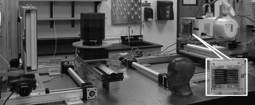
Table TABLE I. lists the scanning and reconstruction parameters. Figure 3 shows the tabletop system with the insertion of the blocker and the phantoms used in our studies. No antiscatter grid was used on the system.
Table 1.
Imaging and reconstruction parameters of the tabletop CBCT system.
| Scan protocol | with blocker | without blocker |
|---|---|---|
| Imaging parameters | ||
| scan mode | Full-fan | Full-fan |
| x-ray energy | 125 kVp | 125 kVp |
| x-ray tube current | 80 mA | 66 mA |
| x-ray focal spot size | 0.4 mm | 0.4 mm |
| pulse width | 13 ms | 13 ms |
| source to detector distance | 1500 mm | 1500 mm |
| source to rotation axis distance | 1000 mm | 1000 mm |
| detector size | 400-by-300 mm2 1024-by-768 pixels | 400-by-300 mm2 1024-by-768 pixels |
| Rotation | circular, 360 deg | circular, 360 deg |
| number of views | 655 | 655 |
| Reconstruction parameters | ||
| reconstruction voxel size | 0.50 mm in all directions | 0.50 mm in all directions |
| reconstruction volume size | 512-by-512-by-350 voxels | 512-by-512-by-350 voxels |
| Algorithm | Modified FDK | Standard FDK |
Figure 3.
The CBCT tabletop system and phantoms. The designed blocker is mounted on the top of collimator and shown in an enlarged insert.
The insertion of the blocker decreases the total exposure onto the imaged object. For a fair comparison, the x-ray tube current was reduced from 80 mA in the scan with the blocker to 66 mA in the scan without the blocker, such that the delivered dose was on a similar level in both scans. The reduction factor of ∼17% was calculated as the ratio of the blocked area to the total area when the beam blocker is inserted.
Two phantoms were used in our studies. The Catphan©600 phantom has a simple cylindrical geometry with a diameter of 200 mm (The Phantom Laboratory, Salem, NY. See Fig. 3). Quantitative evaluations of our method were performed on the phantom inserts. An anthropomorphic head phantom (Pacific Northwest National Laboratory, Richland, WA. See Fig. 3), was used in the second study to further evaluate the proposed method on human imaging. This phantom contains complex anatomies and well represents the challenge of scatter correction on clinical CBCT systems. Bowtie filters are routinely used on clinical CBCT scanners to reduce patient dose and scatter contamination.32 In the head phantom study, we installed a standard bowtie filter on the tabletop system to provide a fair evaluation of our scatter correction method.
In studies presented in this paper, we implemented the proposed data processing steps in Matlab, including scatter estimation∕correction and FDK-based reconstruction.
The scatter estimation error in percentage, E, was calculated for each projection pixel as
| (4) |
where i is the index of the pixel, se is the estimated scatter, and s0 is the ground truth obtained from the fan-beam measurement. To reduce the noise effects, both se and s0 were smoothed before the calculation of E.
We used the mean values, image contrasts and spatial nonuniformity (SNU) in selected regions of interest (ROIs) as the quality metrics of the reconstructed image. Scatter artifacts are more prominent around objects with high contrasts.6 In the Catphan©600 phantom study, the image contrast was calculated as
| (5) |
where μr is the mean reconstructed value inside the ROI and μb is the mean reconstructed value in the surrounding area.
Scatter signals in the projection data cause nonuniformity in the reconstructed image. In the head phantom study, we measured the SNU using a similar definition as in the literature33
| (6) |
Five ROIs with diameters of 10 pixels (5 mm) were selected in the CBCT image of the head phantom, one at the central soft tissue region and the other four around the periphery of the phantom. and in Eq. 6 are the maximum and the minimum of the mean CT numbers of these ROIs, respectively.
RESULTS
Catphan©600 phantom study
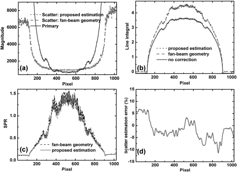
Figures 4a, 4b show the horizontal 1D profiles of measured scatter and primary signals, estimated scatter signals using the proposed method, and line integrals of one projection on the Catphan©600 phantom. The profiles are taken on the midplane, where projection data are not blocked by either left or right strips. The measured scatter is obtained by subtracting the fan-beam projection from the cone-beam projection in the illuminated detector area. The measured SPR is approximately 1.4 around the phantom center as shown in Fig. 4c. In Fig. 4a, it is seen that the estimated scatter profile using our proposed method matches well with the measured result in the central region pixels (from 200 to 800). The percentage error of scatter estimation calculated along the central horizontal line is shown in Fig. 4d, which is within 5% around the object center. Large errors are found around and outside the phantom boundary. Nonetheless, the primary signals are very large in these areas, and the residual SPRs after the proposed correction are still low. Since the errors of the line integral measurements are proportional to log(1 + residual SPR),16 the scatter estimation error has little influence on the accuracy of the reconstructed image.
Figure 4.
1D horizontal profiles of the scatter, primary signals, line integrals, SPRs and relative errors on the Catphan©600 phantom: (a) estimated and measured scatter, primary signals; (b) line integrals of CBCT projections with and without the proposed correction and with a fan-beam geometry; (c) measured SPR using the fan-beam geometry and estimated SPR using the proposed algorithm; (d) percentage error of scatter estimation. Note that, the estimated scatter signals and the ground truth are smoothed before calculating the percentage error.
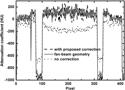
The images obtained in the middle steps in the reconstruction from projections are shown in Fig. 2. The effects of the proposed scatter correction on the reconstructed images are shown in Figs. 567. Figure 5 shows axial views of the reconstructed Catphan©600 phantom. Figure 6 shows the comparison of 1D profiles passing through two high-contrast rods. Figure 7 is the sagittal view of reconstructed images. Our method significantly suppresses the severe shading artifacts present in the scatter uncorrected images [see Figs. 5a, 67a]. The image quality after the proposed scatter correction is comparable to that of a fan-beam CT, which is evident in the comparisons of images [Figs. 5b, 5c] and 1D profiles (Fig. 6). If the fan-beam CT image is used as a “scatter-free” reference, our method reduces the CT number error from 207 to 9 HU in the selected uniform ROI shown as a dashed black circle in Fig. 5c.
Figure 5.
Axial views of the reconstructed Catphan©600 phantom. Display window: [−270, 210] HU; (a) CBCT without correction; (b) CBCT with the proposed scatter correction; (c) fan-beam CT. In figure (c), the dotted line indicates the location where the 1D profiles shown in Fig. 6 are taken. In the selected uniform ROI (marked with dashed black circle), the average CT numbers for (a), (b) and (c) are −107, 91, and 100 HU, respectively. The average reconstruction contrasts are calculated inside the contrast rods, which are marked with index numbers and white solid circles.
Figure 6.
Comparison of 1D profiles passing through the two contrast rods as indicated in Fig. 5c.
Figure 7.
Sagittal views of the reconstructed Catphan©600 phantom. Display window: [−270, 210] HU; (a) CBCT image without correction; (b) CBCT image with the proposed scatter correction.
The image contrasts are calculated for the contrast rods as indicated in Fig. 5c. The results are summarized in Table TABLE II.. In these selected ROIs, the proposed method improves the contrast by a factor of 2.0 on average.
Table 2.
Comparison of the image contrasts measured on the contrast rods of the Catphan©600 phantom.
| ROI | 1 | 2 | 3 | 4 | 5 | 6 | 7 | |
|---|---|---|---|---|---|---|---|---|
| Contrast | CBCT with correction | 137 | 190 | 271 | 1061 | 874 | 249 | 1058 |
| CBCT without correction | 69 | 97 | 141 | 557 | 414 | 121 | 562 | |
| Contrast increase ratio | 2.0 | 2.0 | 1.9 | 1.9 | 2.1 | 2.1 | 1.9 |
Anthropomorphic head phantom study
The scatter correction on the anthropomorphic head phantom is more challenging due to the high variation of the SPR distributions. When a standard bowtie filter is used, the measured SPR is ∼1.0 around the projection center in the AP views, and ∼1.5 in the lateral views.
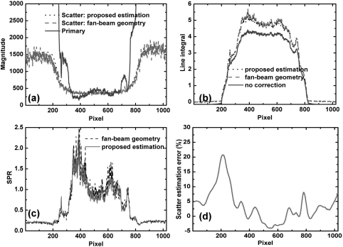
An example of processed projection images on the anthropomorphic head phantom is shown in Fig. 8 and the 1D profiles along the central horizontal line are shown in Fig. 9. The scatter estimation error is comparable to that in the Catphan©600 phantom around the object center. Higher errors are found around the phantom edge. However, the residual SPR is small after correction and the estimated line integrals match well with the ground truth.
Figure 8.
Cone-beam projections and corresponding scatter estimates using the proposed method. (a) blocked cone-beam projection without correction; (b) estimated scatter distribution using the proposed method; (c) cone-beam line integral after correction. The display windows are set to be: (a) [0 20000] and (b) [500 4000] (units in detector units); (c) [0 5].
Figure 9.
1D horizontal profiles of the scatter, primary signals, line integrals, SPRs and relative errors on the anthropomorphic head phantom: (a) estimated and measured scatter, primary signals; (b) line integrals of CBCT projections with and without the proposed correction and with a fan-beam geometry; (c) measured SPR using the fan-beam geometry and estimated SPR using the proposed algorithm; (d) percentage error of scatter estimation. Note that, the estimated scatter signals and ground truth are smoothed before calculating the percentage error.
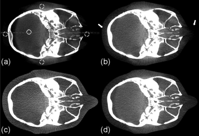
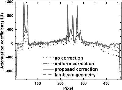
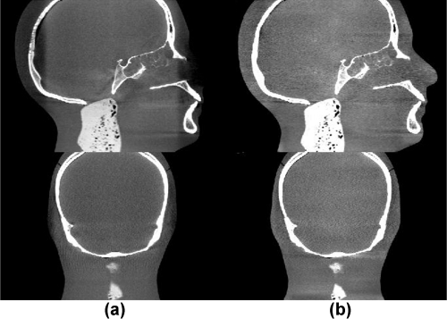
Figure 10 shows the axial views of the reconstructed volumes without correction, with uniform scatter correction, with the proposed scatter correction and with a fan-beam CT geometry as the ground truth. In the uniform scatter correction, scatter signals are assumed constant across the projection field. Using a similar method as in the published literature, we slightly reduced the projection field in the longitudinal direction such that scatter signals were measured in the collimated areas on the top and the bottom of the detector.34 The average scatter signal in these areas was used as the constant scatter estimation for correction. As seen in Fig. 10b, the uniform correction works well in the central region of the reconstructed image. Nevertheless, scatter variation rapidly increases in the radial direction [see Fig. 9a], leading to severe artifacts (>90 HU) toward the periphery of the reconstructed image after the uniform correction. The SNU calculated from the five ROIs as indicated in Fig. 10a is 18%, a slight reduction from 27% in the image with no correction. The challenge of effective scatter correction is well seen in Fig. 10d. The fan-beam geometry greatly suppresses the SPR to an estimated value of around 0.04.24 However, the quality of the reconstructed image is very sensitive to the residual scatter contamination, and the SNU of the fan-beam CT image is still as high as 13%. Our approach achieves a superior imaging performance as shown in Fig. 10c. The proposed method not only reduces the mean CT number error from 97 to 6 HU in the solid white circle as indicated in Fig. 10a, but also further reduces the SNU to only 5%. The improved image quality can also be observed in the comparisons of 1D profiles (Fig. 11), sagittal and coronal views (Fig. 12).
Figure 10.
Axial image reconstructions of the head phantom. Display window: [−200 300] HU. (a) CBCT without correction; (b) CBCT with uniform scatter correction; (c) CBCT with the proposed scatter correction; (d) fan-beam CT as a reference. In the selected uniform soft tissue ROI (marked with a solid white circle in (a)), the average CT numbers from (a) to (d) are: −77, 0, 14, and 20 HU, respectively. The SNUs calculated on the selected five ROIs (marked with solid and dashed white circles in (a)) from (a) to (d) are: 27%, 18%, 5%, and 13%, respectively. The dashed line in (a) indicates where the 1D profiles in Fig. 11 are taken. The white arrows in (b) indicate the severe scatter artifacts.
Figure 11.
Comparison of 1D profiles passing through the central horizontal line indicated in Fig. 10a.
Figure 12.
Sagittal (top) and coronal views (bottom) of the reconstructed head phantom. Display window: [−300 400] HU. Column (a): No correction; (b): scatter-corrected using the proposed method.
To demonstrate the advantages of the proposed reconstruction algorithm expanded from the FDK-based half-fan reconstruction, we generate reconstructed images using the standard FDK algorithm on the projections with the missing primary data estimated via interpolation. The image comparison is shown in Fig. 13. The standard FDK reconstruction on the interpolated projections results in blurring artifacts [Fig. 13c], which disappear in the image of the proposed reconstruction [Fig. 13b].
Figure 13.
Axial CBCT images using different reconstruction schemes. Display window: [−200 300] HU. With (a) no insertion of the beam blocker, no scatter correction, and standard FDK reconstruction; (b) beam blocker in place, proposed scatter correction, and proposed reconstruction; (c) beam blocker in place, missing primary estimated via interpolation, and standard FDK reconstruction.
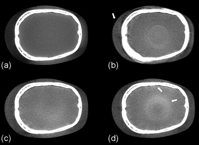
Different blockers were constructed to empirically find the optimal blocker geometry. To demonstrate the effect of the strip gap width (G) of the blocker on the image quality, we generate the reconstructed images using three blockers with different strip gaps on the head phantom, as shown in Fig. 14. A blocker with a small G may block both approximate conjugate rays passing through the same object voxel especially when the voxel has a large distance from the rotational center, resulting in blurring artifacts around the object periphery [indicated by a white arrow in Fig. 14b]. A blocker with a large G obtains inaccurate scatter estimates, and residual scatter artifacts are seen in the areas where the uncorrected SPR is high [i.e., around bones and object center, indicated by white arrows in Fig. 14d]. Based on the comparison studies, 20 mm is chosen as the optimal width of strip gap in our blocker design.
Figure 14.
Axial CBCT images using proposed scatter correction and reconstruction with different strip gaps (G) in blocker design. Display window: [−300 300] HU. (a) no insertion of the beam blocker, no scatter correction, and standard FDK reconstruction. (b) - (d) proposed scatter correction and reconstruction using different blockers: (b) G ≈ 11 mm; (c) G ≈ 20 mm; (d) G ≈ 30 mm. The white arrow in (b) points to the blurring artifacts caused by insufficient primary data (blocking approximate conjugate ray pairs). White arrows in (d) point to blurring and ring artifacts due to scatter estimation error.
DISCUSSION
Measurement-based scatter correction methods have several desired merits in clinical applications, including high scatter estimation accuracy and computational efficiency, no requirement of prior knowledge of the imaged object, and simple implementations on different x-ray CT systems. Nevertheless, the compensation for the missing primary signals employed in the existing approaches requires either extra CT scans or moving the beam blocker during the data acquisition. In this paper, we propose a measurement-based scatter correction method using one single-scan and a stationary blocker, two unique features that remove the last hurdle toward a practical scatter correction solution for different VCT systems. On a more fundamental level, our approach decomposes the projection data acquisition of a CT scan into separate measurements of scatter and primary signals with minimal mutual interference in generating accurate scatter estimates and CT images. The method not only obtains effective scatter correction on the conventional CT images, but also simultaneously acquires accurate scatter distributions which may be used for scatter imaging in the new-concept CT systems.35, 36
A limitation of our method is that we cannot use it together with some of the existing imaging schemes on CT scanners, including half-fan scan and short scan, because the allocation of projection space for scatter measurement reduces the space for primary measurement. These scan modes reduce the number of projections or enlarge the FOV without increasing the detector size. Therefore, they are widely used on the current CBCT systems based on flat-panel detectors, as the detector has a relatively small size and the gantry has a slow rotation. Our method can be further improved to overcome the resultant drawbacks. For example, to extend the FOV without using a half-fan scan, we can implement conventional truncation correction on the projections,37 or use prior patient images to compensate for the missing peripheral data of the reconstructed volume.38 Furthermore, with continuous development of large-size detectors on advanced CT systems, the projection space can be further increased to cover both primary and scatter measurements without sacrificing the FOV. It is worth mentioning that as the detector size increases on the conventional CT scanners, scatter becomes a severe problem for high-quality imaging as well.5, 39 Our approach may find wider applications on these systems due to their large projection coverage in the transverse direction and fast gantry rotation.
The performance of the proposed method has been evaluated using phantoms on a CBCT table-top system. The design of the beam blocker is demonstrated for a circular CBCT scan based on the CT reconstruction theory and the redundancy approximation. Nonetheless, the proposed method can also be used for other scanning trajectories on different CT systems as long as we can design a beam blocker following the three guidelines listed in Sec. 2A1 Finally, in the studies presented in this paper, the geometric parameters of the beam blocker are chosen empirically. The optimal blocker parameters may vary for different clinical applications. Further optimization of the proposed blocker design through patient studies is of high interest in our future investigations.
The insertion of the beam blocker creates an irregular measurement area on the detector, and the standard FDK algorithm cannot be directly used for reconstruction. Different types of existing reconstruction algorithms can be implemented in our method to alleviate this problem. We proposed an FDK-based algorithm based on consideration on implementation simplicity and computational efficiency, although the reconstructed image might not be mathematically optimal. The algorithm consists of standard half-fan reconstructions and several simple weighting steps, and it is therefore readily translatable to the reconstruction software of commercial CT systems.
As a general problem for all postprocessing scatter correction algorithms, the scatter noise is left in the projections after the proposed correction, resulting in a noise level increase in the reconstructed image. More results on this topic have been presented in Ref. 40. The performance of our method can be further improved by implementing an auxiliary noise suppression algorithm, such as the penalized weighted least-square (PWLS) algorithm developed previously.40, 41, 42, 43
CONCLUSIONS
A single-scan scatter correction method is proposed for VCT systems using a stationary beam blocker. On a CBCT tabletop system, our approach reduces the reconstruction error from 207 HU to 9 HU in the selected ROI on the Catphan©600 phantom, and from 97 HU to 6 HU on an anthropomorphic head phantom. Besides the high scatter correction efficacy, the proposed method possesses several advantages over other existing scatter correction approaches, including no dose or scan time increase, no requirement of prior knowledge of the imaged object, high computational efficiency and easy implementations on different VCT systems.
ACKNOWLEDGMENTS
This work was supported by Georgia Institute of Technology new faculty startup funding and the NIH under the Grant No. 1R21EB012700-01A1. The authors would like to thank Dr. Mingshan Sun (Ginzton Technology Center, Varian Medical Systems, Mountain View, California) and Ms. Xue Dong (Nuclear & Radiological Engineering and Medical Physics Programs, The George W. Woodruff School of Mechanical Engineering, Georgia Institute of Technology, Atlanta, GA) for their help on the experiments and all the group members for insightful discussion on the manuscript. They would also like to thank the anonymous reviewers for their constructive suggestions which substantially strengthen the paper.
References
- Virshup G., Suri R., and, Star-Lack J., “Scatter characterization in cone-beam CT systems with offset flat panel imagers,” Med. Phys. 33(6), 2288–2288 (2006). 10.1118/1.2241938 [DOI] [Google Scholar]
- Marchant T. E., Moore C. J., Rowbottom C. G., MacKay R. I., and Williams P. C., “Shading correction algorithm for improvement of cone-beam CT images in radiotherapy,” Phys. Med. Biol. 53(20), 5719–5733 (2008). 10.1088/0031-9155/53/20/010 [DOI] [PubMed] [Google Scholar]
- Zhu L., Wang J., Xie Y. Q., Starman J., Fahrig R., and Xing L., “A Patient Set-up Protocol Based on Partially Blocked Cone-beam CT,” Technol. Cancer Res. Treat. 9(2), 191–198 (2010). [DOI] [PubMed] [Google Scholar]
- Hsiao E. M., Rybicki F. J., and Steigner M., “CT coronary angiography: 256-slice and 320-detector row scanners,” Curr. Cardiol. Rep. 12(1), 68–75 (2010). 10.1007/s11886-009-0075-z [DOI] [PMC free article] [PubMed] [Google Scholar]
- Coolens C., Breen S., Purdie T. G., Owrangi A., Publicover J., Bartolac S., and Jaffray D. A., “Implementation and characterization of a 320-slice volumetric CT scanner for simulation in radiation oncology,” Med. Phys. 36(11), 5120–5127 (2009). 10.1118/1.3246352 [DOI] [PubMed] [Google Scholar]
- Niu T. Y. and Zhu L., “Overview of x-ray scatter in cone-beam computed tomography and its correction methods,” Curr. Med. Imaging Rev. 6(2), 82–89 (2010). 10.2174/157340510791268515 [DOI] [Google Scholar]
- Gao H. W., Fahrig R., Bennett N. R., Sun M. S., Star-Lack J., and Zhu L., “Scatter correction method for x-ray CT using primary modulation: Phantom studies,” Med. Phys. 37(2), 934–946 (2010). 10.1118/1.3298014 [DOI] [PMC free article] [PubMed] [Google Scholar]
- Zhu L., Xie Y. Q., Wang J., and Xing L., “Scatter correction for cone-beam CT in radiation therapy,” Med. Phys. 36(6), 2258–2268 (2009). 10.1118/1.3130047 [DOI] [PMC free article] [PubMed] [Google Scholar]
- Siewerdsen J. H. and Jaffray D. A., “Optimization of x-ray imaging geometry (with specific application to flat-panel cone-beam computed tomography),” Med. Phys. 27(8), 1903–1914 (2000). 10.1118/1.1286590 [DOI] [PubMed] [Google Scholar]
- Endo M., Tsunoo T., Nakamori N., and Yoshida K., “Effect of scattered radiation on image noise in cone beam CT,” Med. Phys. 28(4), 469–474 (2001). 10.1118/1.1357457 [DOI] [PubMed] [Google Scholar]
- Siewerdsen J. H., Moseley D. J., Bakhtiar B., Richard S., and Jaffray D. A., “The influence of antiscatter grids on soft-tissue detectability in cone-beam computed tomography with flat-panel detectors,” Med. Phys. 31(12), 3506–3520 (2004). 10.1118/1.1819789 [DOI] [PubMed] [Google Scholar]
- Star-Lack J., Sun M., Kaestner A., Hassanein R., Virshup G., Berkus T., and Oelhafen M., “Efficient scatter correction using asymmetric kernels,” Proc. SPIE 7258, 1Z1–1Z12 (2009). [Google Scholar]
- Boone J. M. and Seibert J. A., “An analytical model of the scattered radiation distribution in diagnostic-radiology,” Med Phys. 15(5), 721–725 (1988). 10.1118/1.596186 [DOI] [PubMed] [Google Scholar]
- Kyriakou Y., Riedel T., and Kalender W. A., “Combining deterministic and Monte Carlo calculations for fast estimation of scatter intensities in CT,” Phys. Med. Biol. 51(18), 4567–4586 (2006). 10.1088/0031-9155/51/18/008 [DOI] [PubMed] [Google Scholar]
- Colijn A. P. and Beekman F. J., “Accelerated simulation of cone beam x-ray scatter projections,” IEEE Trans. Med. Imaging 23(5), 584–590 (2004). 10.1109/TMI.2004.825600 [DOI] [PubMed] [Google Scholar]
- Zhu L., Bennett N. R., and Fahrig R., “Scatter correction method for X-ray CT using primary modulation: Theory and preliminary results,” IEEE Trans. Med. Imaging. 25(12), 1573–1587 (2006). 10.1109/TMI.2006.884636 [DOI] [PubMed] [Google Scholar]
- Bani-Hashemi A., Blanz E., Maltz J., Hristov D., and Svatos M., “Cone beam x-ray scatter removal via image frequency modulation and filtering,” Med. Phys. 32(6), 2093–2093 (2005). 10.1118/1.1998387 [DOI] [PubMed] [Google Scholar]
- Kwan A. L. C., Boone J. M., and Shah N., “Evaluation of x-ray scatter properties in a dedicated cone-beam breast CT scanner,” Med. Phys. 32(9), 2967–2975 (2005). 10.1118/1.1954908 [DOI] [PubMed] [Google Scholar]
- Gao H. W., Zhu L., and Fahrig R., “Modulator design for x-ray scatter correction using primary modulation: Material selection,” Med. Phys. 37(8), 4029–4037 (2010). 10.1118/1.3457472 [DOI] [PMC free article] [PubMed] [Google Scholar]
- Ning R., Tang X. Y., and Conover D., “X-ray scatter correction algorithm for cone beam CT imaging,” Med. Phys. 31(5), 1195–1202 (2004). 10.1118/1.1711475 [DOI] [PubMed] [Google Scholar]
- Wagner F. C., Macovski A., and Nishimura D.G., “Dual-energy x-ray projection imaging—2 sampling schemes for the correction of scattered radiation,” Med. Phys. 15(5), 732–748 (1988). 10.1118/1.596188 [DOI] [PubMed] [Google Scholar]
- Yaffe M. J. and Johns P. C., “Scattered radiation in diagnostic-radiology—Magnitudes, effects, and methods of reduction,” J. Appl. Photogr. Eng. 9(6), 184–195 (1983). [Google Scholar]
- Maltz J. S., Gangadharan B., Vidal M., Paidi A., Bose S., Faddegon B. A., Aubin M., Morin O., Pouliot J., Zheng Z., Svatos M. M., and Bani-Hashemi A. R., “Focused beam-stop array for the measurement of scatter in megavoltage portal and cone beam CT imaging,” Med. Phys. 35(6), 2452–2462 (2008). 10.1118/1.2924220 [DOI] [PubMed] [Google Scholar]
- Niu T. Y., Sun M. S., Star-Lack J., Gao H. W., Fan Q. Y., and Zhu L., “Shading correction for on-board cone-beam CT in radiation therapy using planning MDCT images,” Med. Phys. 37(10), 5395–5406 (2010). 10.1118/1.3483260 [DOI] [PubMed] [Google Scholar]
- Zhu L., Strobel N., and Fahrig R., “X-ray scatter correction for cone-beam CT using moving blocker array,” Proc. SPIE. 5745, 251–258 (2005). 10.1117/12.594699 [DOI] [Google Scholar]
- Wang J., Mao W. H., and Solberg T., “Scatter correction for cone-beam computed tomography using moving blocker strips: A preliminary study,” Med. Phys. 37(11), 5792–5800 (2010). 10.1118/1.3495819 [DOI] [PubMed] [Google Scholar]
- Feldkamp L. A., Davis L. C., and Kress J. W., “Practical cone-beam algorithm,” J. Opt. Soc. Am. A. 1(6), 612–619 (1984). 10.1364/JOSAA.1.000612 [DOI] [Google Scholar]
- Hsieh J., Computed Tomography Principles, Design, Artifacts, and Recent Advances, 2nd ed: (SPIE, Washington and John Wiley & Sons, Inc., New Jersey, 2009), pp. 262. [Google Scholar]
- Hoppe S., Hornegger J., Lauritsch G., Dennerlein F., and Noo F., “Truncation correction for oblique filtering lines,” Med. Phys. 35(12), 5910–5920 (2008). 10.1118/1.3002416 [DOI] [PMC free article] [PubMed] [Google Scholar]
- Tang X. Y., Hsieh J., Nilsen R. A., Dutta S., Samsonov D., and Hagiwara A., “A three-dimensional-weighted cone beam filtered backprojection (CB-FBP) algorithm for image reconstruction in volumetric CT - helical scanning,” Phys. Med. Biol. 51(4), 855–874 (2006). 10.1088/0031-9155/51/4/007 [DOI] [PubMed] [Google Scholar]
- Jin J. Y., Ren L., Liu Q. A., Kim J., Wen N., Guan H. Q., Movsas B., and Chetty I. J., “Combining scatter reduction and correction to improve image quality in cone-beam computed tomography (CBCT),” Med. Phys. 37(11), 5634–5644 (2010). 10.1118/1.3497272 [DOI] [PubMed] [Google Scholar]
- McKenney S. E., Nosratieh A., Gelskey D., Yang K., Huang S. Y., Chen L., and Boone J. M., “Experimental validation of a method characterizing bow tie filters in CT scanners using a real-time dose probe,” Med. Phys. 38(3), 1406–1415 (2011). 10.1118/1.3551990 [DOI] [PMC free article] [PubMed] [Google Scholar]
- Mail N., Moseley D. J., Siewerdsen J. H., and Jaffray D. A., “The influence of bowtie filtration on cone-beam CT image quality,” Med. Phys. 36(1), 22–32 (2009). 10.1118/1.3017470 [DOI] [PubMed] [Google Scholar]
- Siewerdsen J. H., Daly M. J., Bakhtiar B., Moseley D. J., Richard S., Keller H., and Jaffray D. A., “A simple, direct method for X-ray scatter estimation and correction in digital radiography and cone-beam CT,” Med. Phys. 33(1), 187–197 (2006). 10.1118/1.2148916 [DOI] [PubMed] [Google Scholar]
- Arsenault P. J. and Hussein E. M. A., “Image reconstruction from the Compton scattering of X-ray fan beams in thick/dense objects,” IEEE Trans. Nucl. Sci. 53(3), 1622–1633 (2006). 10.1109/TNS.2006.874074 [DOI] [Google Scholar]
- Wang G., Yu H. Y., and De Man B., “An outlook on x-ray CT research and development,” Med. Phys. 35(3), 1051–1064 (2008). 10.1118/1.2836950 [DOI] [PubMed] [Google Scholar]
- Ohnesorge B., Flohr T., Schwarz K., Heiken J. P., and Bae K. T., “Efficient correction for CT image artifacts caused by objects extending outside the scan field of view,” Med. Phys. 27(1), 39–46 (2000). 10.1118/1.598855 [DOI] [PubMed] [Google Scholar]
- Petit S. F., van Elmpt W. J. C., Lambin P., and Dekker A. L. A. J., “Dose recalculation in megavoltage cone-beam CT for treatment evaluation: Removal of cupping and truncation artefacts in scans of the thorax and abdomen,” Radiother. Oncol. 94(3), 359–366 (2010). 10.1016/j.radonc.2009.12.001 [DOI] [PubMed] [Google Scholar]
- Endo M., Mori S., Tsunoo T., and Miyazaki H., “Magnitude and effects of x-ray scatter in a 256-slice CT scanner,” Med. Phys. 33(9), 3359–3368 (2006). 10.1118/1.2239366 [DOI] [PubMed] [Google Scholar]
- Zhu L., Wang J., and Xing L., “Noise suppression in scatter correction for cone-beam CT,” Med. Phys. 36(3), 741–752 (2009). 10.1118/1.3063001 [DOI] [PMC free article] [PubMed] [Google Scholar]
- Wang J., Zhu L., and Xing L., “Noise reduction in low-dose x-ray fluoroscopy for image-guided radiation therapy,” Int. J. Radiat. Oncol. 74(2), 637–643 (2009). 10.1016/j.ijrobp.2009.01.020 [DOI] [PubMed] [Google Scholar]
- Wang J., Li T., Lu H. B., and Liang Z. R., “Penalized weighted least-squares approach to sinogram noise reduction and image reconstruction for low-dose X-ray computed tomography,” IEEE Trans. Med. Imaging. 25(10), 1272–1283 (2006). 10.1109/TMI.2006.882141 [DOI] [PMC free article] [PubMed] [Google Scholar]
- Wang J., Li T. F., Lu H. B., and Liang Z. R., “Noise reduction for low-dose single-slice helical CT sinograms,” IEEE Trans. Nucl. Sci. 53(3), 1230–1237 (2006). 10.1109/TNS.2006.874955 [DOI] [PMC free article] [PubMed] [Google Scholar]


