Abstract
Objective
The intralaminar screw (ILS) fixation technique offers an alternative to pedicle screw (PS) and lateral mass screw (LMS) fixation in the C7 spine. Although cadaveric studies have described the anatomy of the pedicles, laminae, and lateral masses at C7, 3-dimensional computed tomography (CT) imaging is the modality of choice for pre-surgical planning. In this study, the goal was to determine the anatomical parameter and optimal screw trajectory for ILS placement at C7, and to compare this information to PS and LMS placement in the C7 spine as determined by CT evaluation.
Methods
A total of 120 patients (60 men and 60 women) with an average age of 51.7±13.6 years were selected by retrospective review of a trauma registry database over a 2-year period. Patients were included in the study if they were older than 15 years of age, had standardized axial bone-window CT imaging at C7, and had no evidence of spinal trauma. For each lamina and pedicle, width (outer cortical and inner cancellous), maximal screw length, and optimal screw trajectory were measured, and the maximal screw length of the lateral mass were measured using m-view 5.4 software. Statistical analysis was performed using Student's t-test.
Results
At C7, the maximal PS length was significantly greater than the ILS and LMS length (PS, 33.9±3.1 mm; ILS, 30.8±3.1 mm; LMS, 10.6±1.3; p<0.01). When the outer cortical and inner cancellous width was compared between the pedicle and lamina, the mean pedicle outer cortical width at C7 was wider than the lamina by an average of 0.6 mm (pedicle, 6.8±1.2 mm; lamina, 6.2±1.2 mm; p<0.01). At C7, 95.8% of the laminae measured accepted a 4.0-mm screw with a 1.0 mm of clearance, compared with 99.2% of pedicle. Of the laminae measured, 99.2% accepted a 3.5-mm screw with a 1.0 mm clearance, compared with 100% of the pedicle. When the outer cortical and inner cancellous height was compared between pedicle and lamina, the mean lamina outer cortical height at C7 was wider than the pedicle by an average of 9.9 mm (lamina, 18.6±2.0 mm; pedicle, 8.7±1.3 mm; p<0.01). The ideal screw trajectory at C7 was also measured (47.8±4.8° for ILS and 35.1±8.1° for PS).
Conclusion
Although pedicle screw fixation is the most ideal instrumentation method for C7 fixation with respect to length and cortical diameter, anatomical aspect of C7 lamina is affordable to place screw. Therefore, the C7 intralaminar screw could be an alternative fixation technique with few anatomic limitations in the cases when C7 pedicle screw fixation is not favorable. However, anatomical variations in the length and width must be considered when placing an intralaminar or pedicle screw at C7.
Keywords: Intralaminar screw, Pedicle screw, Lateral mass screw, Anatomic study
INTRODUCTION
The cervicothoracic junction presents numerous challenges to the spine surgeon when planning instrumented fixation in this region. Biomechanically, a potential construct must take into account the transition from the mobile, lordotic cervical spine to the fixed, kyphotic, thoracic segment2). Anatomic constraints also make internal fixation difficult. In addition, the relative lack of epidural space and the increased medial angulation needed for pedicle cannulation at C-7 make pedicle screw (PS) placement at these levels challenging, and potentially increases the risk of damage to adjacent neural structures1,7). The morphology of the C7 lateral mass is associated with great difficulty in obtaining adequate purchase10,11). The C7 lateral mass can sometimes experience failure due to screw loosening or avulsion, particularly at the level of C7 where the thin nature of the lateral mass results in decreased pullout strength8).
The intralaminar screw (ILS) has recently been proposed as an alternative to PS placement at C-79). Although ILSs do not offer the theoretical advantage of 3-column fixation provided by PSs, ILSs may provide a better safety profile due to direct visualization of the lamina at the time of screw insertion, as well as screw position posterior to the thecal sac and exiting nerve roots3). Although this technique has been used clinically, limited information exists regarding the feasibility of ILS placement in the C-7 spine in terms of optimal screw diameter, length, or trajectory.
The use of CT imaging is crucial because it allows the spine surgeon to visualize the relevant bone anatomy and make important decisions in the pre-operative setting1). This is especially true in the C-7 spine, where pedicle size and medial inclination are vital factors that may limit surgical success. In this study, we used computed tomography (CT) imaging of randomly selected patients to define the anatomic requirements and limitations of ILS at C-7, and we compared these data to PS and lateral mass screw placement at this level. Our goal was to determine the applicability of ILS fixation at the cervicothoracic junction and to provide a guide for surgeons hoping to add this technique to their clinical practice.
MATERIALS AND METHODS
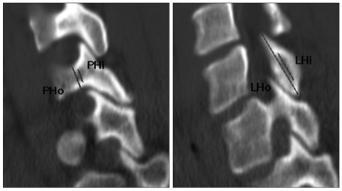
A total of 120 cervical spine CT scans (in 60 men and 60 women) were included in this study. After Institutional Review Board approval, patients were randomly selected for study enrollment via a retrospective review of a hospital trauma registry database. All patients were older than 16 years of age at the time of admission during 2-year period (January 2008-December 2009). All patients had undergone standardized axial bone-window CT scanning at C-7 in a supine neutral position. Patients with CT scan evidence of bony or ligamentous injury, deformity, intraosseous pathology (e.g., tumor or infection), or advanced degenerative changes with disc space collapse and extensive spondylosis were excluded. All CT scans were performed on a Siemens 64-slice CT scanner with 3-mm axial image thickness (Siemens Medical Solutions, Erlangen, Germany). Sagittal and coronal reconstructions were obtained using 1.25-mm thickness slices. CT films were scanned at a resolution of 512×512 pixels, a field of view of 180 mm and CT interactive software was used to edit the images. Linear and angular measurements were made using m-view 5.4 software (Marosis Technologies, Inc., Seoul, Korea). The ideal screw trajectory for ILS and PS placement was determined by one surgeon based on the anatomic axis of the individual lamina or pedicle (Fig. 1, 2). Screw trajectories were then used to determine the maximum screw length without anterior vertebral body cortex violation, while outer cortical and inner cancellous diameters were recorded at the minimum lamina or pedicle width, along the ideal screw trajectory (Fig. 3). Outer cortical and inner cancellous heights were recorded at the minimum lamina or pedicle height, along the ideal screw trajectory (Fig. 4). Lateral mass screw trajectories were used to determine maximum screw length along the ideal screw trajectory (Fig. 5). A line bisecting the spinal canal in the anterior-posterior direction in the axial plane was used to determine the angle of screw trajectory in relation to the midline. All lamina and pedicle measurements were performed bilaterally at C-7 and stratified by the patient's gender and the side of placement. Mean and standard deviation calculations were performed using Microsoft Office Excel. Student's t-test was used for all statistical analyses (Primer of Biostatistics, 6/e, McGraw-Hill Medical). The threshold for statistical significance was set at a p≤0.05.
Fig. 1.
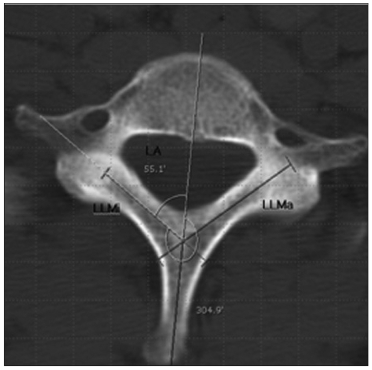
Axial CT scan at C-7 showing optimal ILS length (LLMa : lamina maximum length, LLMi : lamina minimum length) and trajectory (LA : lamina angle to sagittal plane), and determination of medialization angle in relation to the midline. CT : computed tomography, ILS : intralaminar screw.
Fig. 2.
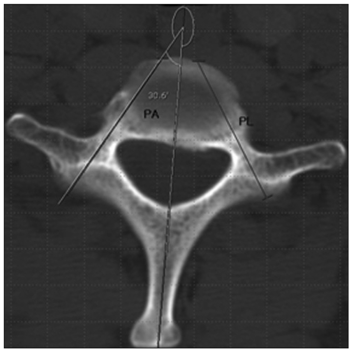
Axial CT scan at C-7 showing optimal PS length (PL) and trajectory (PA : pedicle angle to sagittal plane) and determination of medialization angle in relation to the midline. CT : computed tomography, PS : pedicle screw.
Fig. 3.
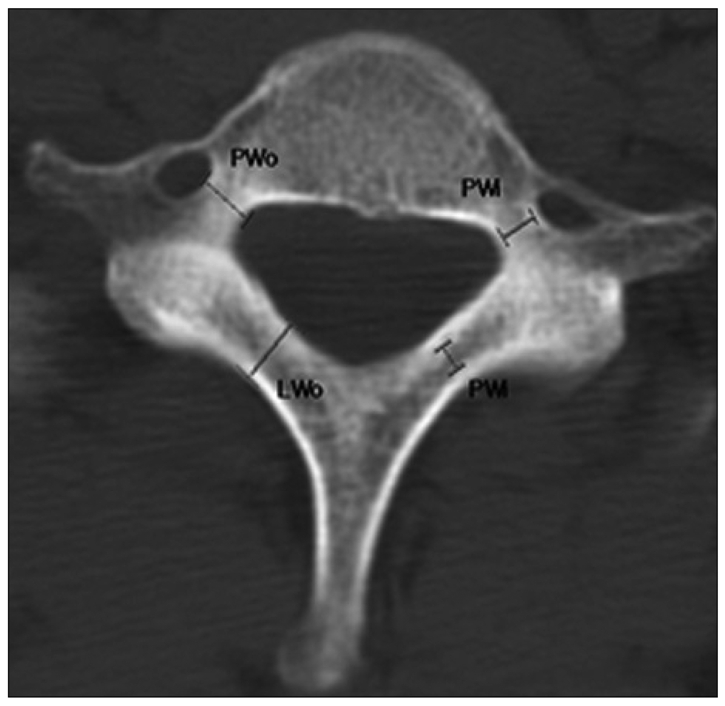
Axial CT scan at C-7 showing measurement of outer cortical width (PWo : pedicle outer cortical width, LWo : lamina outer cortical width) and inner cancellous width (PWi : pedicle inner cancellous width. LWi : lamina inner cancellous width) for each lamina and pedicle. CT : computed tomography.
Fig. 4.
Sagittal CT scan at C-7 showing measurement of outer cortical height (PHo : pedicle outer cortical height. LHo : lamina outer cortical height) and inner cancellous height (PHi : pedicle inner cancellous height, LHi : lamina inner cancellous height) for each lamina and pedicle. CT : computed tomography.
Fig. 5.
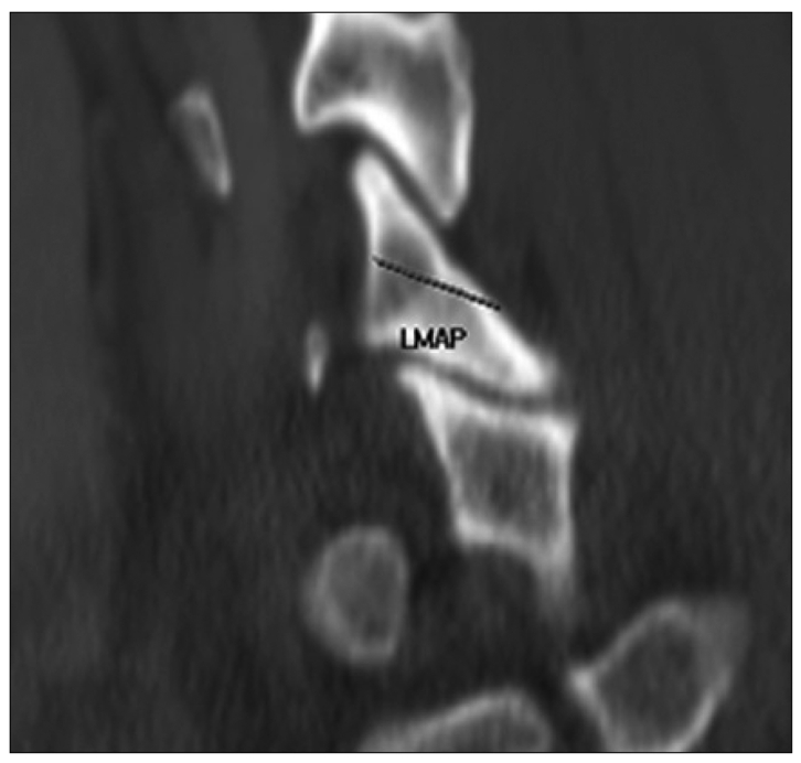
Sagittal CT scan at C-7 showing measurement of lateral mass AP diameter (LMAP). Maximal lateral mass screw length (LM) was calculated by LMAP/cosine 30°.
RESULTS
Patient demographic data
All 120 patients had negative results on CT imaging during evaluation for spinal trauma. The average patient age was 51.7±13.6 years (range, 16-83 years). There was a significant difference in patient age when stratified by gender; however, all patients were skeletally mature adults (men, 51.7±13.6 years; range, 28-83 years; women, 51.7±13.7 years; range, 16-72 years).
Maximum ILS length
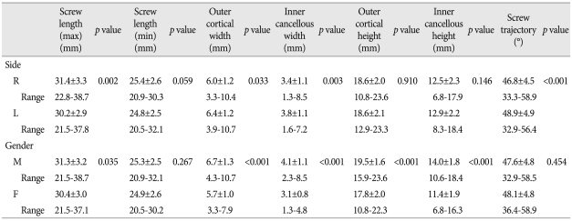
At C-7, the average maximum ILS length was 31.4±3.3 mm, and the shortest screw length in any patient was 22.8 mm (Table 1). When stratified by side of placement, there was no statistically significant difference in screw length on the right versus left side. There was no significant difference in the ILS length based on gender (Table 2).
Table 1.
Comparison of maximum screw length, lamina/pedicle width (outer cortical and inner cancellous), lamina/pedicle height (outer cortical and inner cancellous) and ideal screw trajectory for intralaminar versus pedicle screws at C-7*
*All measurements are reported as the average±SD, and the range. Statistical analysis was performed using Student's t-test
Table 2.
C-7 intralaminar screw length, lamina width (outer cortical and inner cancellous), lamina height (outer cortical and inner cancellous) and ideal screw trajectory stratified by side of screw placement and gender*
*All measurements are reported as the average±SD, and the range. Statistical analysis was performed using Student's t-test
Compared with PS length at C-7, the PS length was an average of 3.1 mm longer than the corresponding ILS length, where the ILS length measured 30.8±3.1 mm compared with the PS length of 33.9±3.1 mm (p<0.01) (Table 1).
Outer cortical and inner cancellous lamina width
The average outer cortical lamina width at C-7 was 6.0±1.2 mm, whereas the inner cancellous width was 3.4±1.0 mm (Table 1). There was no difference in lamina width based on the side of screw placement (Table 2). The laminae in male patients, however, were wider in both outer cortical (by 1.0 mm) and inner cancellous (by 1.0 mm) width compared with females (p<0.01 and p<0.01, respectively). The outer cortical and inner cancellous pedicle diameters were 0.8 mm and 0.7 mm wider than the corresponding lamina at C-7 (p<0.01) (Table 1).
When lamina width was compared with potential screw diameter, 98.3% of the patients accepted bilateral crossing ILSs that were 4.0 mm in diameter with a 1.0-mm clearance at C-7, whereas 99.6% of the patients could accept bilateral pedicle screws at C-7 (Table 3).
Table 3.
Comparison of lamina outer cortical width and pedicle outer cortical width for potential screw diameter
Outer cortical and inner cancellous lamina height
The average outer cortical lamina height at C-7 was 18.6±2.0 mm, whereas the inner cancellous height was 12.7±2.2 mm (Table 1). There was no difference in lamina height based on the side of screw placement (Table 2). The laminae in male patients, however, were 1.7 mm and 2.6 mm wider in the outer cortical and inner cancellous height compared with females, respectively (p<0.001 and p<0.01, respectively). Both outer cortical and inner cancellous lamina heights were 9.9 mm and 8.1 mm wider, respectively, than the corresponding pedicle at C-7 (p<0.01) (Table 1).
Trajectory of the ILS
At C-7, the ideal ILS trajectory was 47.8±4.8° in relation to the spinous process in the axial plane (Table 1). There was no difference in ILS trajectory based on the gender (Table 2). The laminae on left side, however, were 2.1° wider than those on right side, respectively (p<0.01). Although the difference in trajectory between the right and left met statistical significance due to large sample size, this is not likely to be clinically meaningful in guiding screw placement. In comparison with PSs, as expected, significant differences were noted in trajectory due to the difference in the axis of projection of the lamina versus the corresponding pedicle (Table 1). The angle of screw trajectory for ILS differed by 12.7° from PS placement trajectory.
Transpedicular screw length, pedicle width, pedicle height and ideal screw trajectory
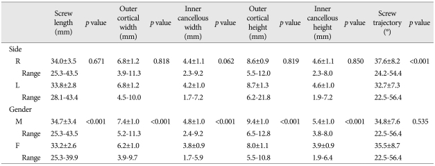
At C-7, the average maximum transpedicular length was 33.9±3.1 mm, and the shortest screw length in any patient was 25.3 mm (Table 1). When stratified by side of placement, there was no statistically significant difference in screw length on the right versus left side (Table 4). The pedicles in male patients, however, were longer in maximum length by 1.5 mm compared with females (p<0.01, respectively).
Table 4.
C-7 transpedicular screw length, pedicle width (outer cortical and inner cancellous), pedicle height (outer cortical and inner cancellous) and ideal screw trajectory stratified by side of screw placement and gender*
*All measurements are reported as the average±SD, and the range. Statistical analysis was performed using the Student's t-test
The average outer cortical pedicle width at C-7 was 6.8±1.2 mm, whereas the inner cancellous width was 4.3±1.0 mm (Table 1). There was no difference in pedicle width based on the side of screw placement (Table 4). The pedicles in male patients, however, were wider in both outer cortical (by 1.2 mm) and inner cancellous (by 1.0 mm) width compared with females (p<0.01 and p<0.01, respectively).
The average outer cortical pedicle height at C-7 was 8.7±1.3 mm, whereas the inner cancellous height was 4.6±1.0 mm (Table 1). There was no difference in pedicle height based on the side of screw placement (Table 4). The pedicles in male patients, however, were 1.4 mm and 1.5 mm wider in the outer cortical and inner cancellous height compared with females, respectively (p<0.01 and p<0.01, respectively).
The ideal transpedicular trajectory was 35.1±8.1° in relation to the spinous process in the axial plane (Table 1). There was no difference in transepdiclar trajectory based on the gender (Table 4). The pedicles on right side, however, were 4.9° wider than those on left side, respectively (p<0.01).
Maximum lateral mass screw length
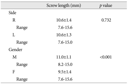
At C-7, the average maximum lateral screw length was 10.6±1.3 mm, and the shortest screw length in any patient was 7.6 mm (Tables 5). When stratified by side of placement, there was no statistically significant difference in screw length on the right versus left side. There was no significant difference in lateral mass screw length based on gender. Of the lateral mass screws, 36.7% were shorter than 10 mm (Table 6).
Table 5.
C-7 lateral mass screw length stratified by side of screw placement and gender*
*All measurements are reported as the average±SD, and the range. Statistical analysis was performed using Student's t-test
Table 6.
Lateral mass ≤10.0
DISCUSSION
Intralaminar screw placement has recently emerged as an alternative to PS fixation at C-2 due to the ease of screw insertion and decreased risk of vertebral artery injury14). Studies have also shown the applicability of this technique in the subaxial cervical spine and the thoracic region3,9). Although cadaveric and CT-based analyses have been performed to assess the feasibility of ILS placement at C-2, there is limited information in the literature regarding the critical proportions of the C-7 laminae as they relate to the use of ILS5).
In this study, CT scans were used to estimate screw size and placement in the C-7 spine; the average estimated ILS screw length at C-7 was 30.8 mm. The shortest maximum ILS length at C-7 in any patient was 22.5 mm compared with 33.9 mm of the shortest maximum PS length at C-7. Although no studies to date have looked at the maximum ILS length in the C-7 spine, Wang13) found the average ILS length at C-2 to be 32 mm (range 27-37 mm) in his morphometric analysis of 38 cadaveric spines. Dean et al.6) reported the mean C-2 ILS length to be 24.8-28.8 mm, depending on whether or not direct cadaveric measurements or CT imaging was used. Based on this information, it appears that the ideal ILS length is similar at C-2 when compared with C-7.
Our findings of variation in lamina length in the C-7 spine are particularly important in the choice of screw size. It should also be noted that male patients were able to accept a 0.8-mm longer ILS at C-7 compared with females, thus gender must also be considered when using this technique. Based on this information, we recommend that screws which are at least 22.5 mm in length can be used safely at C-7. With the advent of pre-operative CT imaging, however, it is likely that longer screws can be used without difficulty at the C-7 level in most patients.
Although screw length is an important factor affecting ILS use in the C-7 region, lamina width is another key variable in the applicability of this technique. In the 2006 study of ILS use at C-2, Wang13) reported that 37% of cadaveric specimens had at least one lamina that would not accept a 3.5-mm screw with 1-mm clearance, whereas this increased to 47% of specimens when 4.0-mm screws were used. Based on these findings, Wang13) concluded that pre-operative CT scanning was crucial prior to ILS placement at C-2 due to the high variability in the thickness of the C-2 lamina. Dean et al.6) also looked at lamina width at C-2, showing that only 72% of specimens had lamina widths >5 mm on CT imaging, whereas 95.2% had laminae >4 mm in thickness. Based on the variability in lamina width at C-2, we sought to measure lamina thickness at C-7 and to compare these findings to screw diameter.
In this study, we found the average outer cortical lamina width at C-7 to be 6.2 mm, and the inner cancellous diameter was 3.6 mm. When lamina width was compared with screw diameter, 98.3% of patients could accept bilateral ILSs that were 4.0 mm in diameter with 1.0-mm clearance at the lamina and 99.6% at the pedicle. This is in striking contrast to previous studies at C-2, where cadaveric measurements have shown that only 53-72% of patients met this size criterion.
Another important feature is the anatomic difference between the lamina of C2 and C7. Anatomically, C7 is very similar to thoracic vertebra in that the spinous process is longer than the other cervical spines, the spinous process is not bifid, and the transverse processes are more prominent. In terms of lamina anatomy, the thickest part of the C7 lamina is around the junction between the middle and inferior thirds, which is similar to the upper thoracic spine. It is also important to note that when the lamina width was compared with the pedicle width at C-7 in our study, the C-7 pedicles were wider than the corresponding lamina by an average of 0.8 mm.
Although screw diameter appears to be similar between ILSs and PSs at the C-7 level, a recent study has shown that ILSs have superior insertional torque and inline pullout strength compared with PSs at C-7. Cardoso et al.4) postulated that the superiority of ILSs in these biomechanical parameters is due to bicortical lamina purchase relative to the corresponding pedicles.
One main advantage of ILS relative to PS placement is the ability to visualize the dorsal lamina surface to guide screw trajectory. A starting hole is typically chosen slightly cephalad at the contralateral spinolaminar junction. The ILS trajectory is then drilled with a hand drill, approximating the dorsal slope of the contralateral lamina, making sure to avoid a ventral cortical wall violation that could result in injury to the spinal cord. After careful palpation of the tract with a ball-tipped probe, this technique is then repeated for the contralateral screw trajectory using a slightly caudal entry point at the spinolaminar junction. Continuously threaded screws are then placed bilaterally to provide maximal screw purchase. Using this technique as a guide, the ideal ILS trajectory relative to the spinous process was measured as 47.8 degree at C-7. Although no studies have looked at this parameter in the C-7 spine, analyses at C-2 have shown the lamina slope angle to be 42.45-48.45°. This compares favorably with the results in our study. It is also important to note that although a rather small variation exists in the angle of ILS trajectory at C-7, striking differences exist in medial inclination during PS placement at this level.
Several limitations exist in our study. First, due to the 3-mm axial CT image thickness, some information relating to lamina and pedicle morphologic characteristics at C-7 may have been missed. Second, due to the computer software used, all length and width measurements were rounded to the nearest millimeter, and all angle readings were rounded to the nearest degree, thereby potentially limiting precision. Finally, although axial CT imaging allows ideal planning for screw length and trajectory, this 2D information must be translated into the 3D operating room setting and should be correlated with surface landmarks to guide screw placement.
CONCLUSION
Although C7 ILSs require intact posterior elements and may not offer the theoretical benefit of 3-column fixation, the safety profiles of C7 ILS relative to PSs and lateral mass screw make this technique very appealing according to CT-based morphological measurements. Therefore, this technique could be used either as a primary fixation technique and as a salvage procedure following failed C7 PS placement, and in the case when the VA course through the C7 transverse foramen or C7 pedicle is not large enough to insert a screw. However, anatomical variations in the length and width must be investigated preoperatively with thin-cut CT scan when placing a C7 ILSs. Also, longer patient follow-up is needed to determine the benefit, the rate of fusion and instrument failure of C7 ILSs.
References
- 1.Albert TJ, Klein GR, Joffe D, Vaccaro AR. Use of cervicothoracic junction pedicle screws for reconstruction of complex cervical spine pathology. Spine (Phila Pa 1976) 1998;23:1596–1599. doi: 10.1097/00007632-199807150-00017. [DOI] [PubMed] [Google Scholar]
- 2.Ames CP, Bozkus MH, Chamberlain RH, Acosta FL, Jr, Papadopoulos SM, Sonntag VK, et al. Biomechanics of stabilization after cervicothoracic compression-flexion injury. Spine (Phila Pa 1976) 2005;30:1505–1512. doi: 10.1097/01.brs.0000167824.19875.e9. [DOI] [PubMed] [Google Scholar]
- 3.Cardoso MJ, Dmitriev AE, Helgeson MD, Stephens F, Campbell V, Lehman RA, et al. Using lamina screws as a salvage technique at C-7 : computed tomography and biomechanical analysis using cadaveric vertebrae. Laboratory investigation. J Neurosurg Spine. 2009;11:28–33. doi: 10.3171/2009.3.SPINE08648. [DOI] [PubMed] [Google Scholar]
- 4.Cardoso MJ, Dmitriev AE, Lehman RA, Helgeson M, Cooper P, Rosner MK. Computed tomography and biomechanical evaluation of screw fixation options at the cervicothoracic junction : intralamina versus intrapedicular techniques. Spine (Phila Pa 1976) 2008;33:2612–2617. doi: 10.1097/BRS.0b013e31818ce3ac. [DOI] [PubMed] [Google Scholar]
- 5.Cassinelli EH, Lee M, Skalak A, Ahn NU, Wright NM. Anatomic considerations for the placement of C2 laminar screws. Spine (Phila Pa 1976) 2006;31:2767–2771. doi: 10.1097/01.brs.0000245869.85276.f4. [DOI] [PubMed] [Google Scholar]
- 6.Dean CL, Lee MJ, Robbin M, Cassinelli EH. Correlation between computed tomography measurements and direct anatomic measurements of the axis for consideration of C2 laminar screw placement. Spine J. 2009;9:258–262. doi: 10.1016/j.spinee.2008.06.454. [DOI] [PubMed] [Google Scholar]
- 7.Desai S, Sethi A, Ninh CC, Bartol S, Vaidya R. Pedicle screw fixation of the C7 vertebra using an anteroposterior fluoroscopic imaging technique. Eur Spine J. 2010;19:1953–1959. doi: 10.1007/s00586-010-1513-8. [DOI] [PMC free article] [PubMed] [Google Scholar]
- 8.Grubb MR, Currier BL, Stone J, Warden KE, An KN. Biomechanical evaluation of posterior cervical stabilization after a wide laminectomy. Spine (Phila Pa 1976) 1997;22:1948–1954. doi: 10.1097/00007632-199709010-00002. [DOI] [PubMed] [Google Scholar]
- 9.Hong JT, Sung JH, Son BC, Lee SW, Park CK. Significance of laminar screw fixation in the subaxial cervical spine. Spine (Phila Pa 1976) 2008;33:1739–1743. doi: 10.1097/BRS.0b013e31817d2aa2. [DOI] [PubMed] [Google Scholar]
- 10.Jones EL, Heller JG, Silcox DH, Hutton WC. Cervical pedicle screws versus lateral mass screws. Anatomic feasibility and biomechanical comparison. Spine (Phila Pa 1976) 1997;22:977–982. doi: 10.1097/00007632-199705010-00009. [DOI] [PubMed] [Google Scholar]
- 11.Merola AA, Castro BA, Alongi PR, Mathur S, Brkaric M, Vigna F, et al. Anatomic consideration for standard and modified techniques of cervical lateral mass screw placement. Spine J. 2002;2:430–435. doi: 10.1016/s1529-9430(02)00461-8. [DOI] [PubMed] [Google Scholar]
- 12.Onibokun A, Khoo LT, Bistazzoni S, Chen NF, Sassi M. Anatomical considerations for cervical pedicle screw insertion : the use of multiplanar computerized tomography measurements in 122 consecutive clinical cases. Spine J. 2009;9:729–734. doi: 10.1016/j.spinee.2009.04.021. [DOI] [PubMed] [Google Scholar]
- 13.Wang MY. C2 crossing laminar screws : cadaveric morphometric analysis. Neurosurgery. 2006;59:ONS84–ONS88. doi: 10.1227/01.NEU.0000219900.24467.32. discussion ONS84-ONS88. [DOI] [PubMed] [Google Scholar]
- 14.Wright NM. Posterior C2 fixation using bilateral, crossing C2 laminar screws: case series and technical note. J Spinal Disord Tech. 2004;17:158–162. doi: 10.1097/00024720-200404000-00014. [DOI] [PubMed] [Google Scholar]


