

Abstract
Size-optimized 32-channel receive array coils were developed for five age groups, neonates, 6 months old, 1 year old, 4 years old, and 7 years old, and evaluated for pediatric brain imaging. The array consisted of overlapping circular surface coils laid out on a close-fitting coil-former. The two-section coil former design was obtained from surface contours of aligned three-dimensional MRI scans of each age group. Signal-to-noise ratio and noise amplification for parallel imaging were evaluated and compared to two coils routinely used for pediatric brain imaging; a commercially available 32-channel adult head coil and a pediatric-sized birdcage coil. Phantom measurements using the neonate, 6-month-old, 1-year-old, 4-year-old, and 7-year-old coils showed signal-to-noise ratio increases at all locations within the brain over the comparison coils. Within the brain cortex the five dedicated pediatric arrays increased signal-to-noise ratio by up to 3.6-, 3.0-, 2.6-, 2.3-, and 1.7-fold, respectively, compared to the 32-channel adult coil, as well as improved G-factor maps for accelerated imaging. This study suggests that a size-tailored approach can provide significant sensitivity gains for accelerated and unaccelerated pediatric brain imaging.
Keywords: magnetic resonance imaging, phased-array coil, pediatric imaging, parallel imaging
The NMR phased array was introduced for spine imaging as a way to increase signal-to-noise ratio (SNR) by simultaneous acquisition from multiple smaller surface coils (1). The concept was immediately successful and quickly extended to brain imaging (2,3). Following the wide-spread implementation of parallel reconstruction methods to accelerate image encoding (4,5), brain arrays have become the standard type of adult head coil with 32-channel brain arrays in use for clinical imaging and higher element brain arrays under development (6).
Pediatric neuroimaging is well suited to benefit from the SNR and acceleration benefits potentially offered by highly parallel detection. The smaller brain structures demand higher spatial resolution with a corresponding reduction in sensitivity from the smaller voxel size. The small size of the infant head and the close proximity of the brain to the surface make young children ideally suited for close-fitting arrays of multiple small elements. However, the same considerations show that attempting to image the smaller pediatric patient in an adult array is suboptimal. The relatively small element size of adult 32-channel adult arrays and wide gap between array element and pediatric head reduces the effective coupling between coil and tissue. This leads to both reduced signal strength and an increased noise fraction from losses in the coil elements (coil noise) relative to the conductive losses in the body (body noise). The SNR is negatively impacted when the “body noise” is reduced to the degree that other noise sources (such as coil noise from resistive losses in the coil components) become significant. Additionally, the spatial frequencies present in the coil sensitivity profiles of the adult array are lowest in the central region (where the pediatric head is positioned) rendering acceleration with parallel imaging suboptimal.
Thus, compromising the size and shape of pediatric brain arrays so that “one size fits all” or using adult brain or knee coils creates the potential for significant degradation of SNR and parallel imaging performance compared to a coil of the appropriate size and shape for a given aged child. As clinical facilities move toward less invasive pediatric imaging with lighter sedation or attempt to image a wider age range of children with no sedation, the ability to obtain high-quality images quickly with high-acceleration rates to reduce motion artifacts becomes increasingly important. In addition to eliminating the risks and side effects associated with anesthesia, the increased cost in pediatric MRI is also a concern. A recent study shows that the cost of the added time and human resources spent for sedation or anesthesia in pediatric MRI is 3.24 and 9.56 times higher, respectively, than a study for awake pediatric populations (7).
Despite the potential benefits, specialized head coils for highly parallel pediatric neuroimaging have not been developed yet. This is likely because rapid head growth in the first years of life requires either a flexible/adjustable array approach or multiple sizes, which span the size range with reasonable discrete increments. Although the flexible/adjustable array has clear cost and work-flow benefits, it is important to quantify the potential gain possible from such an effort before undertaking this formidable engineering challenge. In this work, we developed and tested five incrementally sized 32-channel receive-only head coils targeting pediatric patients spanning an age range of new-born to 7 years old as a step toward engineering a more general flexible/adjustable solution. We based the size increments on brain growth charts (8,9), average head shapes taken from clinical MRI studies and the age needs of our collaborative studies. This led to the construction of arrays nominally sized for new-born infants (neonate), 6-month-old, 1-year-old, 4-year-old, and 7-year-old children. The sensitivity and image acceleration achieved using these optimized 32-channel pediatric brain arrays were compared with a commercially available 32-channel adult head array and a pediatric-sized circular polarized birdcage coil.
MATERIALS AND METHODS
Size-Matched Coil Design
Each coil consists of two parts; a deep posterior segment, covering and a separate “frontal paddle” over the forehead (Fig. 1). The larger posterior section is designed, so the child can lie down into the coil (Fig. 2), rather than a helmet design, which must be pulled down over the head. The eyes and face are completely unobstructed to increase comfort and facilitate visual stimulation for functional studies or anesthesia ventilation if needed. The different helmet sizes were obtained from the surface contours of aligned three-dimensional MRI scans from 20 children of both sexes in each age group. The helmet shape was taken by dilating the 95th percentile contour to accommodate 3-mm foam padding. The final design of the helmet parts were printed in acrylonitrile butadiene styrene (ABS) plastic using a rapid prototyping three-dimensional printer (Dimension SST 1200es, Dimension, Inc., Eden Prairie, MN, USA). The posterior segment of the coil was mounted in a custom-made plastic housing to cover all electronic components and fit the head-end of the scanner’s patient bed.
FIG. 1.

The completed array coil for 1 year old consists of two segments; a deep posterior segmentand a frontal paddle over the forehead (in orange). The eyes and face of the subject are completely unobstructed. a: Finalized coil enclosed in a plastic box; b: inside view of the three-dimensional printed coil formers with coil circuitry; c: tiling geometry diagram of the 32-channel layout; the loop diameters are slightly larger than the diameter of the circle which inscribe the vertexes of the hexagon/pentagons. [Color figure can be viewed in the online issue, which is available at wileyonlinelibrary.com.]
FIG. 2.

Posterior coil segments of all five constructed pediatric array coils. The coil former arebased on the 95th percentile MRI contours of corresponding aged children and have been dilated to accommodate foam padding. The coil formers were three-dimensional printed and enclosed in a plastic box. Mounted mirrors are used to project visual stimulus for research studies.
The statistically obtained head contours were also used to print sized-matched head-shaped phantoms based on the 50% size contour. These phantoms were placed in the tightly fitted coil arrays and were used for coil adjustments at the bench, as well as for imaging evaluations in the MRI scanner.
Coil Construction
The layout of the circular coil elements is established by a hexagonal and a pentagonal tiling pattern (10), which was printed onto the coil former together with standoffs to mount the preamplifiers for each loop. For each age-matched pediatric helmet, we adjusted the tile size appropriately to utilize the desired number of channels (28 channels on the posterior segment and four channels on the frontal paddle). All of the helmets used the same pattern of hexagons and pentagons. The diameters of the loop coils (Table 1) are derived from the size of the pentagon or hexagon tiles; the loop diameter is slightly larger than the diameter of the circle, which inscribes the vertexes of the hexagon/pentagons. The posterior coil segment incorporates 25 hexagons and three pentagons. The frontal-paddle completes the 32 channels with additional four overlapped elements in a linear arrangement of noncircular overlapping elements shaped to fill the available space inside the frontal paddle.
Table 1.
Coil Parameters Obtained from Isolated Coil Elements and When the Coil Elements Have Six Nonresonant Neighbors: Coil Quality Factors (QU, QL), Frequency Shift (fS) During Loading, Equivalent Series Unloaded and Loaded Resistance (rU, rL), and Unloaded Resistive Increase (rIN) Introduced by Surrounded Neighbors
| Neonate | 6 months old | 1 year old | 4 years old | 7 years old | Adult | ||
|---|---|---|---|---|---|---|---|
| Dia. (mm) | 60 | 65 | 72 | 80 | 85 | 90 | |
| Isolated Loops | QU | 256 | 256 | 264 | 273 | 264 | 250 |
| QL | 62 | 55 | 45 | 36 | 30 | 23 | |
| QU/QL | 4.1 | 4.7 | 5.9 | 7.6 | 8.8 | 10.9 | |
| fS (MHz) | −0.3 | −0.3 | −0.4 | −0.5 | −0.6 | −0.7 | |
| rU (Ω) | 0.50 | 0.55 | 0.57 | 0.65 | 0.73 | 0.84 | |
| Six Neighbor Loops | QU | 235 | 237 | 247 | 259 | 253 | 242 |
| QL | 62 | 55 | 46 | 38 | 32 | 24 | |
| QU/QL | 3.8 | 4.3 | 5.4 | 6.8 | 7.9 | 10.1 | |
| fS (MHz) | 0 | −0.1 | −0.2 | −0.3 | −0.4 | −0.5 | |
| rU (Ω) | 0.54 | 0.55 | 0.57 | 0.65 | 0.73 | 0.84 | |
| rL (Ω) | 2.06 | 2.57 | 3.25 | 4.68 | 6.05 | 8.73 | |
| rIN (%) | 8.2 | 7.4 | 6.4 | 5.1 | 4.2 | 3.2 |
We used 16-awg thick tin-plated copper wire to form the loops with bridges bent into the wire to allow the coil conductors to cross-over one another without touching. We divided each loop symmetrically with two gaps, where we place the discrete components (see schematic circuit in Fig. 3). Thus, each half-loop is joined at the top and at the bottom by circuit boards containing discrete components. These two subcircuits were constructed on separate small FR4 circuit boards, manufactured with a rapid prototyping circuit router (T-Tech-7000, T-Tech, Inc., Norcross, GA, USA). The tuning capacitor circuit board contains a variable capacitor C1 (BFC5 808 11339, Vishay Intertechnology, Inc., Malvern, USA) to fine-tune the loop resonance to 123.25 MHz and a series fuse F for passive protection against large currents, potentially induced during transmit. We used fuses with a rating of 570 mA for the 7-year-old, 4-year-old, and 1-year-old arrays and 700 mA for the 6-month-old and neonate coils.
FIG. 3.

Circuit schematic for the coil element and preamplifier chain. The coil element uses three capacitors: The variable capacitor C1 fine-tunes the coil element frequency. Where C2 and C3 are equally valued they provide a capacitive voltage divider at the coil output circuit. A detuning trap is formed around C2 using a variable inductor L and a Diode D. A small coaxial cable connects coil and preamp transforming the element impedance to ZNM, the noise matched impedance for the preamplifier input. The coaxial cable also transforms the input impedance of the preamplifier to a short across D.
The output circuit-board incorporates a capacitive voltage divider (C2, C3; Series 11, Voltronics, Danville, NJ, USA) to impedance match the element’s output to an optimized noise matched impedance, ZNM, desired by the preamplifier (Siemens Healthcare, Erlangen, Germany). The preamplifier also contains a common mode rejection transformer between the first and second stage (11). Additionally, the output circuit board used an active detuning circuit across the match capacitor (C2) consisting of a variable inductor (Coil Craft, Cary, IL, USA) and a PIN diode (Macom, MA4P4002B-402, Lowell, MA, USA) to provide a parallel resonant circuit at the Larmor frequency when the diode is forward biased. Thus, when the PIN diode is forward biased (transmit mode), the resonant parallel LC2 circuit inserts a high impedance in series with the coil loop, blocking current flow at the Larmor frequency during transmit.
To transform the preamplifier input impedance to a high-series impedance within the loop (preamplifier decoupling), we first transformed it to a low impedance (short-circuit) across the parallel LC2 circuit tuned to the Larmor frequency. This parallel LC circuit, in turn, introduces a high-serial impedance in the coil loop. In this mode, minimal current flows in the loop and inductive coupling to other coils is minimized despite the presence of residual mutual inductance. The impedance transformation of the preamplifier input was done by carefully controlling the coaxial cable (UT-85C-form, Micro-Coax, Pottstown, PA, USA) length (~42 mm) between preamplifier and coil terminal, so that it transforms the input impedance of the preamplifier to a short across the diode D.
All preamplifiers were carefully orientated in z-direction to minimize Hall effect issues within the GaAs FET (12). The preamplifiers also contain a bias-T for the PIN diode bias, which allows this bias to be applied to the PIN diode using the 42-mm coaxial cable. Preamp outputs were connected to a cable trap to suppress common mode currents and to avoid interaction with the radiofrequency (RF) transmit system.
Coil Bench Tests
Bench testing during construction was carried out with a custom-made coil-plug simulator, which provides the 10-V power for the preamplifiers and the ability to manually apply bias current (100 mA) to each PIN diode on the array elements. Bench measurements verified the element tuning, active detuning, nearest-neighbor coupling, and preamplifier decoupling for each coil element. Additionally, the ratio of unloaded-to-loaded quality factor (QU/QL) was measured for each size of coil element. QU/QL ratios were obtained with the element under test placed as an isolated loop (no coaxial cable or preamplifier) both external to the array assembly and within the populated but detuned array. To compare the QU/QL for the adult coil, we measured this ratio for a 90-mm diameter loop (corresponding to the size of the loops in the adult array) in an isolated setting and surrounded by six nonresonant neighbors. The effective series resistance contributed by the sample and coil were derived from the measured Q by: QU = ωL/rU and QL = ωL/rL.
After populating all of the elements, the detuning trap circuits were adjusted so that elements not under test could be actively detuned using the coil-plug simulator. Active detuning was measured with a S21 measure between two decoupled (~80 dB) inductive probes slightly coupled to the array element under test. Nearest neighbor coupling was measured using a direct S21 measurement between pairs of elements using coaxial cables directly connected to the preamplifier sockets of the two elements under test. The crossing bridges in the loops were bent to empirically optimize the decoupling, while watching S12 measure between the two loops under test to optimize the decoupling. When measuring the S21 between an adjacent pair, all other elements of the array were detuned.
We measured the preamplifier decoupling of a given loop with all other loops detuned. Preamplifier decoupling was measured as the change in the double-probe S21, when the coil drive coax was terminated in each of two different match conditions (13). In the first case, the coil is terminated with the powered low-impedance preamplifier. In the second case, the coil is terminated with a “power match” load by a dummy preamp consisting of a lumped element termination of impedance .
MRI Data Acquisition and Reconstruction
Data were acquired on a 3-T clinical MRI Siemens scanner (MAGNETOM, Trio a Tim system, Siemens Healthcare, Erlangen, Germany) with 40 mT/m maximum amplitude gradient strength and a maximum slew rate of 200 mT/m/ms. SNR and G-factor measurements were obtained using sized-matched head-shaped phantoms filled with physiologic saline and 0.5 mol/L Gd-DTPA (Magnisvist©, Bayer Schering Pharma, Berlin, Germany) adjusted to a T1 of ~300 ms. To measure SNR, proton density-weighted gradient echo images (repetition time (TR)/echo time (TE)/flip angle (FA) = 30 ms/6 ms/30°, slice = 5 mm, matrix: 192 × 192, field-of-view (FOV): 170 × 170 mm2, and band-width (BW) = 200 Hz/Pixel) were acquired. Noise covariance information was acquired using the same pulse sequence but with no RF excitation. The SNR maps were calculated for images formed from noise-covariance weighted root sum-of-squares (cov-rSoS) of the individual channel images (1,14). The same gradient echo sequence was used for G-factor calculations, but the FOV and matrix size were adjusted according the size of the head phantom to achieve a tight FOV. Thus, we used a FOV of 160 × 160 mm2, 150 × 150 mm2, 140 × 140 mm2, 130 × 130 mm2, and 120 × 120 mm2 for the 7-year-old, 4-year-old, 1-year-old, 6-month-old, and neonate coils, respectively. The G-factor maps were calculated to assess noise amplification in SENSE reconstructions caused by the ill-conditioned unaliasing of the accelerated images and are estimated from the complex coil sensitivities and noise correlation matrix (5). The maximum G-factor was determined after applying a 5 × 5 pixel mean filter to the G-factor maps to avoid biasing the maximum G-factor by noise singularities. The G-factor and SNR gain obtained from the constructed array coils were compared with a commercially available Siemens 32-channel adult head coil (with similar soccer ball layout) and a pediatric-sized circularly polarized birdcage coil (18 cm diameter and 19 cm length).
In addition to the bench performance tests, we measured the amount of power from the RF body coil dissipated in the detuned array and verified that component heating was minimal. We measured the percentage of the body RF power dissipated in the detuned array coil by comparing the RF body coil forwarded/reflected power levels required to achieve a 180° excitation in a phantom with and without the detuned array coil present. This power should ideally be unaltered by the presence of the detuned array coil. We considered the arrays validated when the ratio of the absorbed power (Pforw – Prefl) with and without array measurements is between 0.9 and 1.1. The component heating checks included heating by gradient eddy currents and by RF transmit fields. To evaluate the heating induced by eddy current, we applied 28,000 bipolar gradient pulses of 38 mT/m amplitude and 0.26 ms duration on each axis simultaneously. Each bipolar pulse was repeated every 2.5 ms. We scanned the temperature of the helmet interior using an infrared thermometer (FLUKE-61, Fluke, Everett, WA, USA) before and immediately after the scan. To assess possible component heating during RF transmit, the detuned coil and phantom were scanned for 15 min with a body coil RF B1 of 30 μT applied at a 10% duty cycle and TR of 60 ms; an RF power level well above the specific absorption rate (SAR) limit. The helmet temperature was measured before and after this scan and considered validated, when maximum component temperatures rises were below 2°C.
Human subjects were scanned to demonstrate the sensitivity of the coils, after review of the institution’s human research committee and informed consent was obtained from each subject or subject’s legal guardian. To optimize workflow in a clinical environment, it is useful to determine the best fitting coil before the subject enters the scan room. For this reason, we also constructed mock copies of the helmets (with no electronics or housings) to allow MR techs or researchers to quickly check the head size of the subject. Additionally, the tightly fitting helmets constrain the use of conventional MRI ear muffs for scanner acoustic noise mitigation requiring the use of pediatric “mini muffs” (Natus Medical Inc., San Carlos, CA, USA) in additional to pediatric ear plugs (Microsonic Inc., Ambridge, PA, USA). In vivo measurements were also performed on an adult female subject, who fit well into the 4-year-old and 7-year-old arrays [although her head is longer than a large 4-year-old in the anterior–posterior direction]. The use of a healthy adult subject allowed us to directly compare in vivo coil performance between the 4-year-old, 7-year-old, and the 32-channel adult coil within the same individual by measuring SNR in the sagittal, axial, and coronal planes using a 192 × 192 mm2 FOV and the same sequence parameters as the phantom SNR measurements. The same sequence parameters introduced a slight T1-weighting in the in vivo brain images. Accelerated anatomic imaging was demonstrated by comparison of the 4-year-old and the adult array coil using a T1-weighted three-dimensional MPRAGE sequence, with TR/inversion time (TI)/TE/FA= 2.53 s/900 ms/3.25 ms/7°, matrix = 192 × 192 × 176, 1-mm isotropic voxel size, BW = 200 Hz/pixel, acceleration of R = 3, 1 average, and an acquisition time of 3:10 min. Additionally T2-weighted transversal anatomic images were acquired in a neonate imaged in the neonate array using a turbo spin echo sequence with TR/TE/FA = 7.16 s/91 ms/120°, matrix = 384 × 384, FOV: 150 × 150 mm2, number of slices: 44, voxel size: 0.4 × 0.4 × 2 mm3, BW=195 Hz/pixel, two averages, and acquisition time of 6:58 min. For the 4-year-old array, the adult subject was imaged with T2-weighted turbo spin echo images with TR/TE/FA = 6.81 s/97 ms/126°, matrix = 447 × 447 mm, FOV: 192 × 192, number of slices: 22, voxel size: 0.4 × 0.4 × 2 mm3 BW = 150 Hz/pixel, two averages, and acquisition time of 4:16 min. These turbo spin echo scans were not accelerated.
RESULTS
Table 1 shows the QU/QL-ratios of the constructed array coils for both a single isolated coil loop and a loop surrounded by its six nonresonant neighboring elements. The unloaded-to-loaded Q-ratios for the hexagons ranged from 3.9 to 8.9. The QU/QL ratio for the adult 32-channel head array coil with a loop diameter of 90 mm was 10.9. QU/QL ratios for isolated elements (no neighbors present) show overall slightly higher values indicating the presence of losses in the neighboring coils. Using the QU values with and without the neighbors as a direct measure of rU (the component losses), we found that the percentage change in rU incurred by adding the six nearest neighbor untuned loops decreased nearly linearly with coil diameter.
Figure 4 shows representative noise correlation matrices for all five pediatric arrays obtained from noise-only phantom images. The noise correlation ranges from 0.011 to 28% with an average over all five constructed arrays of 12% for the off-diagonal elements. Bench tests showed a range of decoupling between nearest neighbor elements of the posterior array section from −14 to −22 dB with an average of −17 dB. Next neighboring coupling between the frontal paddle and the posterior array, which has no overlap, ranges from −6 to −12 dB. The coupling between next-nearest neighbors (nonoverlapped pairs) obtained from all five arrays ranged from −9 to −22 dB. In addition to these geometric decoupling levels, the elements received an additional reduction of 24 dB from preamplifier decoupling. In the transmit state, active PIN diode detuning provided >40 dB isolation between the tuned and detuned states.
FIG. 4.

Noise correlation matrices of all five constructed pediatric 32-channel brain arrays acquired with the size-matched loading phantoms. The overall average noise correlation (all coils) is 12%. [Color figure can be viewed in the online issue, which is available at wileyonlinelibrary.com.]
All of the constructed array coils passed the safety tests without additional adjustment beyond the bench adjustments. We observed a slight increase in RF power (ranging from 1.0 to 3.2%), when the detuned arrays were present inside the scanner. During and after the heating tests, we did not measure any changes in temperature above 1°C on critical components (e.g., cable traps) or at the inner side of the array helmets.
Figure 5 shows the SNR maps in the age-specific head-shaped phantoms for images combined with the noise-covariance weighted root sum-of-squares (cov-rSoS). The SNR in sagittal slice acquired through the center of each coil is shown. In comparison with the 32-channel adult coil the neonate coil showed an SNR increase at the phantom center of 1.25-fold and a 3.6-fold increase at the edge of the phantom. The 6-month-old coil showed a 1.15-fold SNR benefit at the phantom center and a 3-fold SNR increase at the periphery. For the 1-year-old array, the pediatric-sized 32-channel coil increased SNR 1.1-fold center and 2.6-fold at the edge compared to the adult 32-channel array. The corresponding SNR increase for the 4-year-old coil was 1.09-fold and 2.3-fold. Finally, the 7-year-old pediatric array showed a 1.7-fold SNR improvement at the phantom edge and nearly identical SNR (gain of 1.04-fold) at the center. Each pediatric array shows a drop in peripheral SNR at the location corresponding to the gap between the frontal paddle and the posterior array. Measurements of the “global brain” SNR showed an average SNR gain of 2.8-, 2.3-, 2.0-, 1.8-, and 1.6-fold for the neonate, 6-month-old, 1-year-old, 4-year-old, and 7-year-old coils, respectively, compared with the adult 32-channel array. The region of interest (ROI) used for that measurement is shown in Fig. 5 as an overlay on the birdcage SNR map. When we compared the average “whole phantom” SNR between the constructed pediatric array coils and the 32-channel adult array, we estimated an average SNR increase 2.2-, 1.8-, 1.6-, 1.4-, and 1.2-fold, for the neonate, 6-month-old, 1-year-old, 4-year-old, and 7-year-old coils, respectively.
FIG. 5.

SNR comparisons between sagittal images obtained from the sized-matched head phantoms using the pediatric brain array coils (first row), the 32-channel adult brain array coil (second row), and a CP birdcage coil (third row). The images show that the highest SNR gain occurs closest to the surface of the constructed array. In the “brain” center of the phantoms the SNR is only slightly improved. The superimposed ROI on the birdcage coil SNR maps correspond to the regions used in the average brain SNR measurement.The 7-year-old phantom was too big to fit into the pediatric birdcage coil. [Color figure can be viewed in the online issue, which is available at wileyonlinelibrary.com.]
For the neonate, 6-month-old, 1-year-old, and 4-year-old arrays, we were able to compare a pediatric-sized quadrature birdcage (the 7-year-old phantom is too large to fit). In this comparison, the 32-channel pediatric arrays provided 5.4- 5.1-, 4.8-, and 4.2-fold higher peripheral SNR than the pediatric-sized birdcage. The center of head SNR was 1.3-, 1.2-, 1.1-, and 1.05-fold higher than the pediatric-sized birdcage. The SNR of the “global brain” ROIs, showed an average increase of 3.4-, 3.1-, 2.8-, and 2.4-fold for the neonate, 6-month-old, 1-year-old, and 4-year-old arrays, respectively, compared with the birdcage coil. The average SNR across the whole phantom was 2.6-, 2.2-, 1.9-, and 1.3-fold improved, respectively.
Figure 6 shows a direct SNR comparison in all planes of the 4-year-old, 7-year-old, and the adult 32-channel array using the adult subject with a narrow enough head to fit in these coils. The in vivo SNR maps validate the findings with the head-shaped phantoms. In vivo comparison with the adult 32-channel array showed 2.2-fold SNR improvement at the brain cortex and a 9% (1.09-fold) higher SNR in the center of the brain for the 4-year-old array. The 7-year-old array showed a 1.5-fold SNR gain at the cortex and a small SNR increase of 5% (1.05-fold) at the center.
FIG. 6.

In vivo SNR comparisons in sagittal, axial, and coronal planes between a commercial available 32-channel adult coil, the 7-year-old coil, and the 4-year-old coil using a same small head-sized adult in all coils. Compared to pediatric heads, the adult head is slightly bigger in anterior–posterior direction. This leads to a more prominent gap between frontal paddle elements and the posterior elements. The in vivo measurements match the phantom SNR results and verify that a sized matched array approach shows a peripheral SNR increase. [Color figure can be viewed in the online issue, which is available at wileyonlinelibrary.com.]
Figure 7 shows the inverse G-factor maps in the transverse plane for one-dimensional and two-dimensional accelerations derived from coil sensitivity profiles and noise correlations from the phantom measurements for all the constructed coils as well as the commercial 32-channel adult array scanned with an aged-matched phantom. Figure 8a shows the average G-factors from the maps of Fig. 7. The peak G-factors are graphically summarized in Fig. 8b and reflect the worst case scenario regarding noise amplifications during parallel image reconstruction. The constructed coils produce overall lower G-factors in all cases, roughly providing one additional unit of acceleration for a given noise amplification factor. To quantify the regional G-factor improvement compared with the adult 32-channel array, Fig. 8c,d shows the average G-factor in a central ROI and peripheral ROI of the head phantom. The largest improvements (lower G-factors) for the pediatric arrays were found in the central brain region. For example, for R = 3 in the anterior–posterior direction, the pediatric coils showed an average of 31% less noise amplification in the central ROI compared with the adult array (with maximum improvement of the neonate coil of 47% and minimum improvement of 16% for the 7-year-old coil). The improvement in G-factor in the peripheral ROI was not as much as in the central regions. For the peripheral ROI, the improvement across all the constructed array coils was 14% for R = 3 (maximum gain in the neonate coil of 24% and minimum gain in the 7-year-old coil of 4%). Figure 9 compares the 4-year-old and adult 32ch array’s accelerated imaging capability in a sagittal MPRAGE acquisition using an acceleration factor of R = 3 in the same adult subject (with narrow enough head to fit the 4-year-old array). The combination of reduced G-factor and improved cortical SNR translates to improved image quality in the MPRAGE. Figure 10 shows an unaccelerated T2-weighted transverse turbo spin echo image, acquired with 0.4-mm in-plane resolution and 2-mm slice thickness using the neonatal coil and the 4-year-old coil. This acquisition demonstrates the SNR strength for high-resolution anatomic scans of the constructed pediatric coil arrays.
FIG. 7.

Transverse maps of 1/G-factor obtained from the constructed array coils and the adult coil using the age-matched head phantoms. The FOVs were chosen as tight as possible during image acquisition to avoid underestimation of G-factors. The maps were calculated using images from PD-weighted GRE sequence and noise correlation information. The pediatric brain arrays show over-all lower average and peak G-factor values compared with the 32-channel adult coil.
FIG. 8.

Average and peak G-factors for adult and pediatric 32-channel arrays from the data in FIG. 7. a: Whole-slice average G-factors comparing the overall noise amplification during parallel image reconstruction. b: Peak G-factors for the slice, reflecting the worst-case noise amplification. c, d: G-factor averages in a central and peripheral ROI. The highest relative gain by going to the size-appropriate coil was achieved in the central brain region. The pediatric coils show overall more favorable peak G-factors for both one-dimensional and two-dimensional accelerations directions. The scans were accelerated in the anterior–posterior direction (for one-dimensional acceleration) and anterior–posterior and right-left direction for the two-dimensional accelerations. [Color figure can be viewed in the online issue, which is available at wileyonlinelibrary.com.]
FIG. 9.

Fully encoded sagittal 1-mm isotropic MPRAGE images with GRAPPA acceleration factor of R = 3. For coil performance comparison, the images were acquired with the 4-year-old (a, c) and the adult 32-channel (b, d) array coils using the same adult subject. Corresponding close ups (c, d) show better image details using the size matched array coil for 4-year-old children.
FIG. 10.
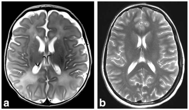
T2-weighted transverse high resolution (0.4 × 0.4 × 2 mm3) turbo spin echo (TSE) images, acquired using the neonate and 4-year-old coils. Both images have been intensity normalized. a: Four-day old sedated neonate imaged in 6:58 min using the 32-channel neonate array for a separate clinical study. b: Image acquired (4:16 min) in the 4-year-old array of an adult with a small enough head to fit this coil.
DISCUSSION
2In this study, we present the design, construction, and characterization of five size-matched 32-channel receive-only array coils for highly accelerated pediatric brain imaging at 3 T. The characterization of coil performance included the evaluation of noise correlation, SNR, and G-factor maps using size-matched phantoms. Furthermore, the coil performance was evaluated with in vivo scanning on adults with small enough heads to fit the 4-year-old and 7-year-old pediatric coils and in a child evaluated in a separate clinical study. Our evaluation shows that a tailored array approach for size-matched pediatric brain MRI provides significant SNR gains for both accelerated and unaccelerated imaging. Furthermore, it underscores the inefficiency of using adult or single channel volume coils for pediatric brain examination. For the optimal use of array detection, regarding SNR and encoding performances, the surface coils should closely surround the imaging volume of interest. Furthermore, handling and patient comfort are important considerations when targeting pediatric populations. Although the approach required building multiple arrays to size-match each age-group, it is important to understand the potential gains of this approach to motivate investment in a flexible, or adjustable size approach.
A number of technical issues arise in the implementation of a large channel-count array with relatively small element size. In particular, the interelement decoupling, QU/QL ratio, SNR performance, and location of preamplifiers become more challenging, whereas commercial 32-channel head coils for adults with a loop diameter of ~90 mm are typically constructed out of flexible circuit material, array coils with smaller elements size show eddy current losses in the conductors of the neighboring elements can be significant and lead to a lower QU/QL ratio and SNR using this circuit approach (6,15). Spatially sparse conductors, such as wire, as well as relocating the preamplifier and its motherboard 2–3 cm from the loop elements, reduces the losses in the copper for the dense arrays. We also found that the ability to mechanically optimize the overlap between two loops by bending the wire facilitated the element decoupling procedure. However, we still could measure a reduced unloaded Q, when the loop under test was placed in an array configuration suggesting that losses within the conductors of neighboring elements were still present. We found that the negative impact of these losses increases as the loop diameter is reduced. While loop diameters of 90 mm show only an increased resistance of 3.2% due to the neighboring elements, the increase was 8.2% for the 60 mm diameter elements used for the neonate array coil. However, the QU/QL-ratio for all constructed array coils show sample noise dominance, but this metric was also less favorable for smaller loop sizes (e.g., 6-month-old or neonate arrays.) Thus, maintaining body noise dominance in the small loop elements is more challenging for two reasons; the intrinsically smaller QU/QL-ratio in the isolated loop, and the increased effect of losses within the surrounding elements.
When loop elements become smaller, and therefore, the array is more densely packed, the positioning of the preamplifier becomes more challenging. For both, SNR gain with optimum noise figure and preamplifier decoupling, it is important to align the preamplifier to z-direction (12). This reduced degree of freedom for preamplifier positioning is conflicting likely with optimum cable routing. Mainly, the routing of the output coaxial cable should not pass near (<~2cm) of another preamplifier’s input to avoid positive feedback loops. This was especially challenging for the neonate and the 6-month-old array coils.
Measurements of the transmitted RF field with and without the pediatric 32-channel coils inside the scanner ranges from 1.0 to 3.2% in transmit power difference. This indicates sufficient coil element detuning and suppression of common mode currents on the cables. The modest increase in power requirement, when arrays are present, might be due to power dissipation in the copper-wire used in the element construction, cables, and element-adjacent preamplifier, including circuitry and motherboard. Similar observation can be found in literature about large-count array coils for adults (6,16).
The noise correlation between the coil elements over all 32-channel arrays revealed a mean coupling value of 12%. However, some pairs in each coils showed correlations over 35%. All of these high coupling pairs were identified to be adjacent to each other but not overlapped. These were the coil pairs, where one loop was located in the posterior coil segment and the other in the frontal paddle. Examination of different paddle positions on the phantom showed significant changes in the level of correlations of those pairs. However, the noise-covariance weighted root sum-of-squares reconstruction method is able to reduce the impact of such element coupling within the array by utilizing coil sensitivity and noise correlation information. This image reconstruction method offers the array coil designer increased freedom in array layout, beyond overlapping elements. But the presence of this “gap” between frontal paddle elements and the posterior elements led to the gap seen in the SNR maps, as seen in the sagittal maps.
All constructed arrays showed increased SNR compared with the adult 32-channel coil. Because of the spatial SNR variation associated with array coils, the SNR gain of the constructed pediatric array coils was higher at the periphery of the brain but also showed moderate improvements at the center. Furthermore, the SNR comparison in the “whole phantom” ROI showed less favorable SNR improvements compared to the “whole brain” ROI. The whole phantom ROI included areas such as the face, for which the pediatric brain array coils are not intended to image, whereas the comparison coils (such as the adult 32-channel and the pediatric birdcage) are more effective at receiving signal in this area.
Comparisons between G-factor maps obtained from commercially available 32-channel adult head coil and the five constructed arrays, showed that the multisize approach by using incrementally sized 32-channel coils for pediatric imaging produce overall significantly more favorable G-factors compared to a “one-size fits all” approach, required when adult coils are used. The spatial variations of the G-factors still show the highest noise amplification in the central brain regions when the pediatric coil arrays are used. However, in relative comparison with the 32-channel adult coil, the central brain regions show the highest improvement in G-factor. The G-factor improvement is likely attributed to the close fitting and smaller elements, which offers a stronger spatial modulation of signal intensity and thus improved ability to unalias folded images (SENSE method) or synthesize spatial harmonics (SMASH or GRAPPA methods). Thus, the accelerated images obtained from the pediatric arrays provide the ability to accelerate at approximately one unit higher at a given noise amplification compared with the adult array.
In addition to hardware optimization in pediatric MRI, image reconstruction algorithms should be adapted to the specific requirements of the pediatric imaging and the small loop diameters of the pediatric arrays. For example, comparisons with the 32-channel adult head coil images show that the pediatric array images are darker at the center of brain. In contrast, the SNR maps show that these regions are not reduced in SNR. Instead, the signal intensity normalization algorithm performs suboptimally on the small-loop pediatric array coils although our postprocessing software can handle these intensity variations. Another example image reconstruction improvements in pediatric MRI is shown in the recent study from Vasanawala and coworkers (18), demonstrating a combination of parallel imaging and compressed sensing (17) in pediatric MRI with promising results. This study translated successfully the L1-SPIR-iT method (18) into a feasible clinical pediatric MRI protocol and obtained high image quality with a reduced acquisition time. In principle, the compressed sensing and parallel imaging approach is synergistic with the SNR and acceleration improvements of the dedicated pediatric array coils.
The use of MRI in pediatric imaging remains a challenging undertaking due to practical, methodological, and analytical issues that arise when imaging young populations. Beyond clinical MRI applications, there is a progressive use of functional MRI (fMRI) in pediatric research studies (19–23). Functional MRI allows monitoring of functional developmental processes during brain maturation and may provide the basis for early detection of pathophysiologic processes; a prerequisite for functionally guided therapeutic interventions. Achieving this goal requires high quality structural and functional MRI data, often in studies without anesthesia. Head motion has been identified as the most common reason for scan failure in pediatric fMRI (24). The ability to highly accelerate structural scans is therefore desirable for pediatric brains studies since it reduces scan time (and the probability of motion) significantly. For single shot fMRI acquisitions, the acceleration does not translate directly to improved motion mitigation (but to reduced susceptibility distortions), but due to the tightly fitting array coils the degree of motion is mechanically constrained. The close-fitting array coils limit the ability of the subject to rotate their freely head. Furthermore the narrow fit around the neck prohibits the subject from sliding out of the coil. These design choices raise the concern about the psychologic reaction to having one’s head “captured.” However, our collaborative pediatric imaging studies (as well as our experience with adult subjects in the 4-year-old and 7-year-old arrays) showed that the helmets do not induce additional anxiety. Note that the frontal paddle is held in place with a simple articulating hose tubing, so a typical 4-year-old child would have no problem exiting the coil on its own.
Although the helmets constrain motion, they still allow side-to-side motion. Although centimeters of motion are not possible, the head can move against the compressed padding. In this respect, the situation is not much different from using the vacuum bead immobilization approach (commonly used at children’s hospitals) or wedging foam pads within the adult coil to immobilize the subject. Ultimately, the helmets were designed to be fairly comfortable to lie on with minimal foam padding. This stems from the bowl shaped support for the occipital pole, the curving neck support and the lack of any structures over the eyes, nose, and mouth region. The latter is particularly important to avoid rebreathing exhaled CO2 rich air (CO2 inhalation causes anxiety or panic).
Using tight fitting pediatric array coils clearly reduces the range of choices of noise protection. In fact, common used MRI ear-muffs for noise mitigation are not compatible with the arrays. Often, however, regular ear-muff are not used on younger children (< about 3 years old) anyway, when vacuum bead head-holders are used to immobilize the anesthetized head inside the adult coil. In our approach, we used insertable pediatric ear-plugs together with external “mini-muffs.” These single use devices are made from thin acoustic barrier foam (similar to the insert plugs) and adhere with via an adhesive surface to the pinna. When auditory stimulus is needed, it must be applied either through an ear-bud based MRI compatible system or externally, through a loudspeaker powerful enough to be heard thru the ear protection.
An additional potential application for the increased parallel imaging performance of the pediatric arrays is to use the reduced gradient encoding to lower acoustic noise rather than reducing susceptibility distortion (25). In this scenario, the echo-planar imaging echo train length is not shortened, but the reduced number of phase encoding steps afforded by accelerated acquisition is used to lower the BW (and gradient amplitude) of each readout line, resulting in an acoustically quieter scan. If the spatial resolution and acquisition duration are unaltered in the single-shot echo-planar imaging sequences the ramp time of the readout gradient, a sampling BW, and the gradient amplitude can both reduced by a factor approximately equal to the acceleration rate lowering the Lorentz forces within the gradient coil. This has potential for a more comfortable environment during a pediatric MRI scan, or it can be used when auditory stimulations are applied for fMRI.
Finally, there is a potential to reduced scan-slot durations by using accelerated scans and reducing the need for anesthesia and sedation. The latter slows down the pediatric MRI patient flow and raises the costs significantly (7), thereby reducing the population of patients that can benefit from the diagnostic abilities of MRI. Dedicated sized-matched pediatric array coils can potentially relieve these limitations and establish pediatric MR imaging to a wider range of children with no or lighter sedation/anesthesia. Ultimately, this can reduce costs in pediatric radiology divisions and offset the high cost of age-specific array coils.
CONCLUSIONS
Five size-matched 32-channel close-fitting array coils for pediatric head imaging were constructed and tested with phantoms and in vivo MRI scans. We compared the constructed arrays to adult 32-channel head coils regarding parallel imaging and SNR performance. The coils provided significant SNR gain over commercially available adult 32-channel head coils. Significant improvements in parallel imaging performance were also obtained. The ability to increase acceleration in structural MRI scans are expected to reduce the possibility of severe motion artifacts, a prerequisite for attempts to extend the range of children who can be scanned with no or lighter sedation/anesthesia.
ACKNOWLEDGMENTS
The authors thank Siemens Healthcare, Erlangen, Germany, for providing Tim Trio MRI scanner specific components.
Grant sponsor: National Institutes of Health; Grant numbers: U01MH093765, P41RR14075, R21EB008547, R21HD058725, R01EB009756, R01NS055754; Grant sponsor: Ellison Medical Foundation.
REFERENCES
- 1.Roemer PB, Edelstein WA, Hayes CE, Souza SP, Mueller OM. The NMR phased array. Magn Reson Med. 1990;16:192–225. doi: 10.1002/mrm.1910160203. [DOI] [PubMed] [Google Scholar]
- 2.Hayes CE, Hattes N, Roemer PB. Volume imaging with MR phased arrays. Magn Reson Med. 1991;18:309–319. doi: 10.1002/mrm.1910180206. [DOI] [PubMed] [Google Scholar]
- 3.Wald LL, Carvajal L, Moyher SE, Nelson SJ, Grant PE, Barkovich AJ, Vigneron DB. Phased array detectors and an automated intensity-correction algorithm for high-resolution MR imaging of the human brain. Magn Reson Med. 1995;34:433–439. doi: 10.1002/mrm.1910340321. [DOI] [PubMed] [Google Scholar]
- 4.Griswold MA, Jakob PM, Heidemann RM, Nittka M, Jellus V, Wang J, Kiefer B, Haase A. Generalized autocalibrating partially parallel acquisitions (GRAPPA) Magn Reson Med. 2002;47:1202–1210. doi: 10.1002/mrm.10171. [DOI] [PubMed] [Google Scholar]
- 5.Pruessmann KP, Weiger M, Scheidegger MB, Boesiger P. SENSE: sensitivity encoding for fast MRI. Magn Reson Med. 1999;42:952–962. [PubMed] [Google Scholar]
- 6.Wiggins GC, Polimeni JR, Potthast A, Schmitt M, Alagappan V, Wald LL. 96-Channel receive-only head coil for 3 Tesla: design optimization and evaluation. Magn Reson Med. 2009;62:754–762. doi: 10.1002/mrm.22028. [DOI] [PMC free article] [PubMed] [Google Scholar]
- 7.Vanderby SA, Babyn PS, Carter MW, Jewell SM, McKeever PD. Effect of anesthesia and sedation on pediatric MR imaging patient flow. Radiology. 2010;256:229–237. doi: 10.1148/radiol.10091124. [DOI] [PubMed] [Google Scholar]
- 8.Nellhaus G. Head circumference from birth to eighteen years. Practical composite international and interracial graphs. Pediatrics. 1968;41:106–114. [PubMed] [Google Scholar]
- 9.Roche AF, Mukherjee D, Guo SM, Moore WM. Head circumference reference data: birth to 18 years. Pediatrics. 1987;79:706–712. [PubMed] [Google Scholar]
- 10.Wiggins GC, Triantafyllou C, Potthast A, Reykowski A, Nittka M, Wald LL. 32-channel 3 Tesla receive-only phased-array head coil with soccer-ball element geometry. Magn Reson Med. 2006;56:216–223. doi: 10.1002/mrm.20925. [DOI] [PubMed] [Google Scholar]
- 11.Hergt M, Oppelt R, Vester M, Reykowski A, Huber K, Jahns K, Fischer H. Low noise preamplifier with integrated cable trap. Proceedings of the 15th Annual Meeting of ISMRM; Berlin, Germany. 2007. p. 1037. [Google Scholar]
- 12.Possanzini C, Boutelje M. Influence of magnetic field on preamplifiers using GaAs FET technology. Proceedings of the 16th Annual Meeting of ISMRM; Toronto, Canada. 2008. p. 1123. [Google Scholar]
- 13.Reykowski A, Wright SM, Porter JR. Design of matching networks for low noise preamplifiers. Magn Reson Med. 1995;33:848–852. doi: 10.1002/mrm.1910330617. [DOI] [PubMed] [Google Scholar]
- 14.Kellman P, McVeigh ER. Image reconstruction in SNR units: a general method for SNR measurement. Magn Reson Med. 2005;54:1439–1447. doi: 10.1002/mrm.20713. [DOI] [PMC free article] [PubMed] [Google Scholar]; Magn Reson Med. 2007;58:211–212. Erratum in. [Google Scholar]
- 15.Kumar A, Edelstein WA, Bottomley PA. Noise figure limits for circular loop MR coils. Magn Reson Med. 2009;61:1201–1209. doi: 10.1002/mrm.21948. [DOI] [PMC free article] [PubMed] [Google Scholar]
- 16.Schmitt M, Potthast A, Sosnovik DE, Polimeni JR, Wiggins GC, Triantafyllou C, Wald LL. A 128-channel receive-only cardiac coil for highly accelerated cardiac MRI at 3 Tesla. Magn Reson Med. 2008;59:1431–1439. doi: 10.1002/mrm.21598. [DOI] [PMC free article] [PubMed] [Google Scholar]
- 17.Vasanawala SS, Alley MT, Hargreaves BA, Barth RA, Pauly JM, Lustig M. Improved pediatric MR imaging with compressed sensing. Radiology. 2010;256:607–616. doi: 10.1148/radiol.10091218. [DOI] [PMC free article] [PubMed] [Google Scholar]
- 18.Lustig M, Alley M, Vasanawala SS, Donojo DL, Pauly JM. L1 SPIRiT: Autocalibrating Parallel Imaging Compressed Sensing. Proceedings of the 17th Annual Meeting of ISMRM; Honolulu, USA. 2009. p. 379. [Google Scholar]
- 19.Waber DP, De MC, Forbes PW, Almli CR, Botteron KN, Leonard G, Milovan D, Paus T, Rumsey J. The NIH MRI study of normal brain development: performance of a population based sample of healthy children aged 6 to 18 years on a neuropsychological battery. J Int Neuropsychol Soc. 2007;13:729–746. doi: 10.1017/S1355617707070841. [DOI] [PubMed] [Google Scholar]
- 20.Poldrack RA, Pare-Blagoev EJ, Grant PE. Pediatric functional magnetic resonance imaging: progress and challenges. Top Magn Reson Imaging. 2002;13:61–70. doi: 10.1097/00002142-200202000-00005. [DOI] [PubMed] [Google Scholar]
- 21.O’Shaughnessy ES, Berl MM, Moore EN, Gaillard WD. Pediatric functional magnetic resonance imaging (fMRI): issues and applications. J Child Neurol. 2008;23:791–801. doi: 10.1177/0883073807313047. [DOI] [PubMed] [Google Scholar]
- 22.Evans AC. The NIH MRI study of normal brain development. Neuroimage. 2006;30:184–202. doi: 10.1016/j.neuroimage.2005.09.068. [DOI] [PubMed] [Google Scholar]
- 23.Almli CR, Rivkin MJ, McKinstry RC. The NIH MRI study of normal brain development (Objective-2): newborns, infants, toddlers, and preschoolers. Neuroimage. 2007;35:308–325. doi: 10.1016/j.neuroimage.2006.08.058. [DOI] [PubMed] [Google Scholar]
- 24.Yerys BE, Jankowski KF, Shook D, Rosenberger LR, Barnes KA, Berl MM, Ritzl EK, Vanmeter J, Vaidya CJ, Gaillard WD. The fMRI success rate of children and adolescents: typical development, epilepsy, attention deficit/hyperactivity disorder, and autism spectrum disorders. Hum Brain Mapp. 2009;30:3426–3435. doi: 10.1002/hbm.20767. [DOI] [PMC free article] [PubMed] [Google Scholar]
- 25.de Zwart JA, van GP, Kellman P, Duyn JH. Reduction of gradient acoustic noise in MRI using SENSE-EPI. Neuroimage. 2002;16:1151–1155. doi: 10.1006/nimg.2002.1119. [DOI] [PubMed] [Google Scholar]