Abstract
This paper presents a novel method which reconstructs any desired 3D image resolution from raw cone-beam CT data. X-ray attenuation through the object is approximated using ridgelet basis functions which allow us to have multiresolution representation levels. Since the Radon data have preferential orientations by nature, a spherical wavelet transform is used to compute the ridgelet coefficients from the Radon shell data. The whole method uses the classical Grangeat’s relation for computing derivatives of the Radon data which are then integrated and projected to a spherical wavelet representation and back-reconstructed using a modified version of the well known back-projection algorithm. Unlike previous reconstruction methods, this proposal uses a multiscale representation of the Radon data and therefore allows fast display of low-resolution data level.
Keywords: Computed tomography, 3D ridgelet, Spherical wavelets
Introduction
Cone-beam tomography is currently used in x-ray industrial and medical imaging applications. Recent advances in computational tomography (CT) technology such as micro-tomography and spiral scanning have significantly increased scanning velocities and resolutions [16]. A modern tomography machine is capable to acquire a large number of images at high resolutions, whereby these systems require more and more increasing storage capabilities. For instance, a typical 3D acquisition for small animals amounts up to 256 Mb more or less of hard disk space [2]. A full reconstruction involves a large number of acquisition planes at maximal resolution of the particular object to examine. Overall, researchers are forced to throw away many of the acquired projections after the reconstruction process because the storage resources are limited [28]. In consequence, scanners have been devised as to have increasing storage capacity. Of course this solution is clearly limited and ignores the fundamental problem of efficient access to information, defined as the capacity to satisfy user needs. These user needs include a fast way for data retrieving, which can be performed via a highly scalable representation of information, it should allow the retrieving of the requested information at any resolution and at any spatial location [11]. Therefore, a first step ahead is to identify a work frame which defines its basic dimensions as resolution, quality, and spatial location.
Regarding the data representation in tomography, a first alternative consists in directly using the tomography projections. Traditionally, a minimal number of projections are used for reconstruction since raw projection archiving is dependent on the computational resources. Besides, this representation definitely limits access to the information at any of the previously defined dimensions [4]. Different signal representations have been used for compression. Bae et al. [3, 4] propose to compress projections as if they were sinograms, obtained by stacking individual projections of a perpendicular plane to the digitalization axis in increasing angular order. Sinogram data, unlike projections, have a highly correlated structure and therefore they should be very compressible. Sinograms are obtained by integration processes on neighboring object regions at multiple directions and therefore they constitute a natural object directional analysis. For the compression task, Bae et al. use JPEG-LS [1] in a near-lossless compression mode so that the absolute difference between every reconstructed pixel and its original value is previously bounded. Bae proposes an error bound smaller than the one introduced by the digitalization process under the hypothesis that if the distortion compression levels are lower than the digitalization noise, it can be held that distortion will be imperceptible. Unfortunately, JPEG-LS is not scalable compression technique [12] and no random or multiresolution access is possible. Sánches [17] compresses by computing a 1D wavelet transform on the tomography projections and using a conventional arithmetic codec. Yet this representation produces acceptable compression rates, this strategy is limited because the wavelet detects only unidimensional discontinuities and no 3D multiresolution reconstruction is possible. That is to say, provided that each projected point is the result of the line integral and that the wavelet approaches co-planar points, detected discontinuities correspond to lines. Another alternative is presented by Chen [10] in positron emission tomography applications. The whole idea is to perform a principal component analysis (PCA) on a temporal series of sinograms and to reduce the number of temporal components by ruling out smaller components. Its drawback comes from the information loss as well as from the difficulty to implement highly scalable reconstruction methods.
A second alternative is to represent tomographic data from the reconstructed object. The wavelet transform is the best 1D sparse signal representation, i.e., this transform permits to represent maximal information with a minimum of coefficients. This representation has been broadly used in tomography [18] by extending ordinary 1D wavelets to 2D or 3D problems. This is usually achieved using analysis frames constructed from the tensor product of 1D wavelets so that signals are isotropically analyzed. This is why wavelets are considered as sub-optimal image representations since images are basically anisotropic. These limitations have been overcome by mixing the multidirectional image analysis and multiresolution schemes [27]. Two representation families have been proposed: adaptive and statics. Adaptive refers to that directional information is firstly determined for each image and multiresolution properties are then assigned to regions with any particular orientation. Statics means that the image projections are searched upon a set of multiscale basis set with directional preference [27]. In both cases the fundamental problem is a search of the directional information. However, multidirectionality is much more complicated to reach because this requires oversampling strategies and a non separable filter design [20]. In addition, these constructions are defined over continuous domains, making it very difficult in its implementation for the discrete case. Since the fundamental problem with directional transforms is the multidirectional information analysis and the analysis basically arises from the cone-beam projections, we propose to use information from the projections for inferring singularity plane information of the object. Our main contribution is to use the raw cone-beam data and to provide them with multiresolution properties under a ridgelet analysis frame. This representation constitutes a straight framework for multiresolution reconstruction, application of denoising methods and efficient access to information. Besides, this method permits to store the whole set of acquired projections because the process is invertible for retrieving back the original projections.
The remainder of this paper is structured as follows. In Methods the concepts of cone-beam tomography, ridgelet transform are introduced and the proposed method is described. In Results some experimental results, which validate the present proposal, are presented. Finally, Discussion and Conclusions presents the discussion and the conclusions.
Methods
A multiresolution representation is built upon the 3D Radon transform data, obtained from cone-beam projections. This Radon data calculation requires planar integrals, but cone-beam rays project only line integrals to the detector plane and they are not parallel. If the acquisition rays were parallel, the sum of line values on the detector plane would coincide with the plane integral, a fundamental hypothesis which is of course violated in case of the cone-beam geometry. This difficulty has been overcome using the Grangeat's relation [14] which allows us to calculate the Radon data derivatives from raw cone-beam data. This approach avoids the whole integral calculation using the best possible estimation of this value, i.e., what is detected in the acquisition plane.
Hereafter the Radon and cone-beam transforms are defined. Afterwards, the Grangeat's relation is discussed, followed by a brief introduction of the ridgelet transform. Derivative data from Grangeat's relation are integrated for obtaining the spherical Radon shell data. Finally, a spherical wavelet representation is used for reconstructing the Radon data within a multiresolution analysis frame using a ridgelet transform.
3D Radon Transform
The continuous 3D Radon transform for a 3D function  , Rf (τ, θ, γ) is defined as:
 |
1.1 |
where  ,
,  is a preferential orientation, δ(x) the Dirac delta function,
  an integration plane whilst τ is the distance from the plane
  to the origin. This transform corresponds to the integral over the function values
  in the plane
  and corresponds to the sum of various parallel line integrals.
Cone-Beam Transform
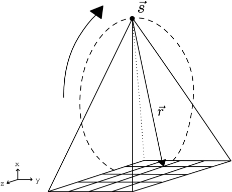
A cone-beam projection is obtained from the line integrals diverging from a vertex point  , which corresponds either to the position of the x-ray source in computerized tomography (CT; Fig. 1) or to the focal point of a converging collimator in single photon emission computed tomography (SPECT).
Fig. 1.
Cone-beam acquisition: a particular ray is emitted from the origin  (source) in the
  direction. The detected value corresponds to the line integral and is used to calculate the plane integral of the Radon transform. Difficulties for calculating Radon transform arise because rays are not parallel
A cone-beam data acquisition consists of various cone-beam transforms  for a number of vertex positions along a given curve in the direction
  , that is:
 |
1.2 |
Radon Data Calculation
Grangeat [14] established a relationship between cone-beam and Radon data:
 |
1.3 |
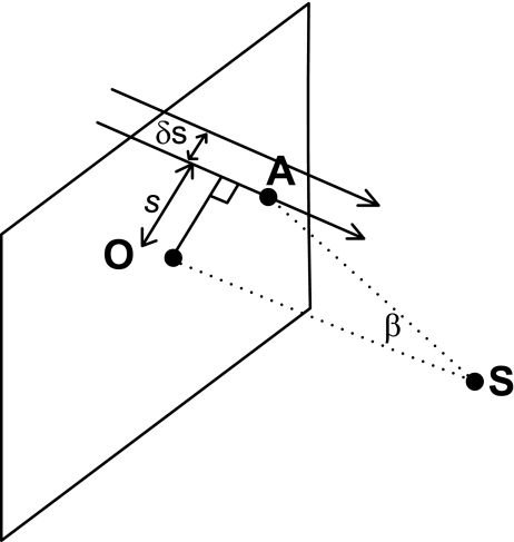
where SO is the distance between the origin and the source, SA is the distance between the source and an arbitrary point A over the detector plane located in a line l perpendicular to the origin, as observed in Fig. 2, where β is the angle between SO and SA, Xf[t, θ, γ, s] is the detected value at a distance s from the detector center along the line l. This relation establishes that the integral variation over parallel planes, separated by an infinitesimal distance, coincides with the variation of neighboring planar integrals generated over cone-beam geometry. These planar integrals are weighted, depending on the source position and the plane detector orientation.
Fig. 2.
Grangeat's relation is illustrated, the basic idea is that the difference of integral values separated by a small distance ∆s is proportional to the change of the Radon data
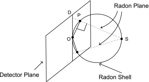
On the other hand, the continuous 3D radon transform Eq. 1.1 can be represented upon a spherical shell with diameter OS since the Radon points associated to the source S must satisfy OP ⊥ SP, as shown in Fig. 3. Given a source point S, the planes through this point can only define a limited set of Radon transforms, which in turn, are identified with a 3D point P. The Grangeat's relation allows us to calculate the Radon data derivatives upon a spherical spatial shell so that each point on the sphere determines a vector which generates an integration Radon plane as illustrated in Fig. 3. Thanks to this transformation we can calculate actual Radon data but on a spherical representation. A multiresolution analysis, as will be observed later in the paper, results much more complicated because of this spherical representation.
Fig. 3.
The Radon shell slice generated by the point S. The shell is formed by any point P whose line segment OP is orthogonal to SP. The Grangeat's data are not homogeneously distributed upon the sphere
Ridgelets
The ridgelet transform has proven to be a 2D and 3D optimal representation of linear singularities in images [8, 9]. Usually, the image is analyzed in terms of a basis called the ridgelet function  , defined as follows:
 |
where ψ(x)a, b is a 1D wavelet with scale a > 0 and centered at b. The basis  corresponds to a ridge with a shape ψ(x)a,b oriented to the plane direction
  .
.
The ridgelet continuous transform CRTf (a, b, θ, γ) of a function  , is the projection of f onto the ridgelet basis
  , that is to say:
 |
1.4 |
where  . Ridgelet coefficients CRTf(a, b, θ, γ) allow to reconstruct f from:
 |
where  is a normalization constant, dependent on the parameters a, b, θ, γ. The CRT can be re-written in terms of a Radon transform:
 |
1.5 |
in this case, Rf(t, θ, γ) performs a directional analysis of  in planes parallel to
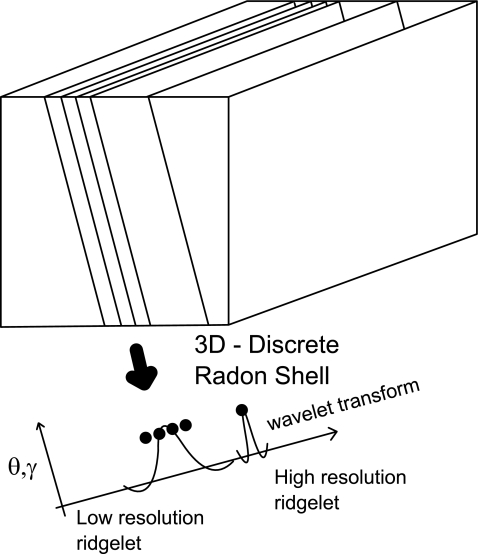
  . If the plane orientation (θ, γ) is fixed, linear singularities (planes, lines) are mapped onto single points, co-linear in the Radon domain. Then a 1D wavelet is likely the best approximation to these points and therefore to linear singularities. Figure 4 shows how parallel planes are mapped onto points whilst the wavelet is used to approximate their spatial distribution. The resultant coefficients correspond to the ridgelet transform because of oriented nature of the Radon transform, as seen in Fig. 4.
Fig. 4.
Ridgelet transform of parallel planes. Thanks to the 3D Radon transform, planes are mapped to co-linear points. A wavelet transform is able to approach singularities of the mapped planes, resulting in a multiscale and multidirectional representation of such singularities
Information contained in the different planes is now projected to the wavelet basis which very naturally approaches singularities.
Discrete Ridgelet Transform
A discrete ridgelet can be obtained by merely sampling the projection of the Radon data onto the wavelet bases Eq. 1.5. However, such strategy requires sampling on both the wavelet and Radon data. The drawback is that a discretization of the Radon space is achieved through approximations to planar integrals. Two strategies have been proposed in the literature for making these approximations
A spatial plane is divided in parallel lines which are then digitized in the spatial domain [21].
The image is transformed to the Fourier domain and the integral values are calculated on discrete lines, with specific orientations defined on this domain, thanks to the slice-projection theorem [5].
In both cases, the line integral value is an approximation to the continuous line integral value. Unlike previous methods which discretize the line for calculating the integral value, our method straightforwardly uses the line integrals from cone-beam projections. A direct use of these projections allows exact reconstructions of the object, with no need to approximate lines or to use a redundant discretization of them as will be showed later. Besides, this method uses every cone-beam projection for reconstruction.
Discrete Ridgelet Transform from Cone-Beam
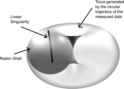
Provided that a point in the Radon space represents directional information, a multiresolution analysis in the Radon space is also directional by nature. Figure 5 illustrates how linear singularities are distributed upon the Radon shell surface, which in turn forms a torus when circular acquisitions are available. In cone-beam acquisitions the directional information is not co-linear while the resulting data are distributed upon a Radon shell, as observed in Fig. 5. This is a major obstacle as to make a uni-dimensional analysis using a wavelet transform, but a multiscale analysis may be carried out on the sphere shell itself. The propagation of the information direction was thus determined by a spherical wavelet analysis. The whole method can be summarized as follows: Grangeat's relation is used for calculating the Radon derivatives, from which the Radon shell data are computed. Then, these data are represented in a multiscale space upon the sphere using axi-symmetric spherical wavelets so that the resultant data coincide with the ridgelet transform.
Fig. 5.
A linear geodesic discontinuity is drawn upon the Radon shell. This Radon shell forms the torus when multiple circular acquisitions are available
Discrete ridgelet calculation requires Radon values rather than their derivatives, which are firstly integrated. Each Radon shell is centered in the origin and the its derivative values integrated over n derivative samples at the circumferences corresponding to fixed azimuth planes γ, using the following approximation to the Radon value:
 |
with  is the middle of the distance between the source and the origin and w is an integration weight (△θ for a conventional quadrature integration method).
After the integration process, Radon values are available all over the sphere. Usually, calculation of the ridgelet transform is carried out over parallel planes which correspond to the co-linear Radon data. Unfortunately, the Radon data associated to the cone-beam acquisition are distributed over the sphere but they are not parallel. This problem was overcome using spherical wavelet representations which allow a multiscale representation of geodesic geometries. The spherical wavelet transform herein used [6] projects the function onto a wavelet in the spherical domain. The wavelet is dilated or rotated by stereographically projecting the spherical wavelet onto the tangent plane to the North Pole. Therein, Euclidian operations can be performed on a conventional wavelet representation and afterward the wavelet is lifted back to the sphere
 |
where  is an invariant measure on the sphere,
  is a rotation operator with parameters ρ ∈ SO(3), being SO(3) the group of rotations under the composition operation and Da ∈ R+ is the function of dilation on the sphere which includes the stereographic projection operation [6]. The projection of Rf over the spherical wavelet corresponds to our ridgelet definition over the sphere
  .
.
Multiresolution Reconstruction
Finally, a multiresolution reconstruction is achieved by modifying the classical 3D Radon reconstruction formula. The proposed reconstruction process is based on a 3D Radon inverse through a multiscale version of the parallel filtered back-projection algorithm [16]:
 |
1.6 |
where  is a version of f at scale a and
  is the second derivate of the Radon data at scale a. Unlike previous reconstruction methods, the proposed strategy uses a multiscale version of the Radon shell, within which the number of samples is lower than the obtained with traditional ones, accelerating the reconstruction process. Additionally, as the reconstruction is multiscale, each sample contains more information about linear singularities presented in the object. The scaled version of
  is computed using a discrete weighted controlled wavelet frame on the sphere [6], as follows:
 |
where p, q are indexes of an equiangular partition of the sphere wjpq. This partition at the jth resolution, is defined as  , where
  a bandwidth and
  are dilations of the mother wavelet at the discrete values
  with
with  . Using the following relation and the previous frame, original data are easily reconstructed at any scaled version of Rf:
 |
Results
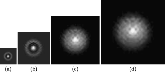
The method was twofold evaluated: simulations were firstly carried out on a sphere and the Shepp–Logan phantom, while precision of the reconstruction was assessed by comparing the original image with the reconstructed result, using a conventional peak signal to noise ratio (PSNR) measure. Usually, for compression applications it is well known that a PSNR larger than 30 dB is considered as convenient for actual applications. Synthetic phantoms were fabricated as follows: simple forms such as a sphere were cone-beam projected using a CT projection simulator [22] while simulations on the Shepp–Logan phantom corresponded to the central slice of Shepp–Logan. The source-to-origin distance was set to 6 cm, the number of detectors per cone-beam projection was 128 × 128, the size of the 2D detector plane was 2 × 2 cm and the number of projections was set to 128. Each reconstructed image contains 128 × 128 × 128 voxels. Once cone-beam projections were generated, the Radon shell was computed for each projection. This calculation was carried out in Matlab as well as the multiresolution Grangeat-type image reconstruction. The algorithms run on a Intel Xeon X5460 Quad-Core 3.16 GHz with 8 GB in RAM. For the Grangeat-type formula implementation, the numerical differentiation was performed using a linear interpolation. Also, 128 different rotations with 128 s derivate evaluations were computed to cover up each projection's Radon shell. Finally, the spherical wavelet corresponded to the first Gaussian derivate of an equiangular grid of 256 × 256 with four levels of dilations. The multiresolution reconstruction process was performed with the parallel back-projection relation, in two back-projection steps for the meridional planes and a unique back-projection for the axial planes.
Figure 6 shows results for three different multiscale reconstructions of the phantom sphere. The low resolutions present some artifacts attributed to the reconstruction with low-resolution ridgelets, but this effect is lost when more ridgelet coefficients are added to the final representation, as expected.
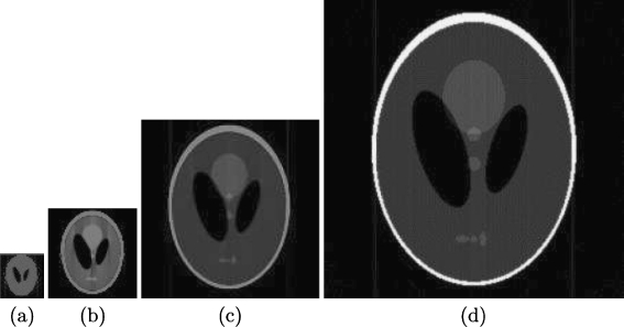
Fig. 6.
Multiresolution reconstruction of the Shepp–Logan central slice brain phantom
Figure 7 shows different resolution levels of reconstruction of the Shepp–Logan brain phantom. In this case, the object is much more complex and different luminance shapes are present within the object. The importance of this evaluation is that the internal anisotropy of these objects is not altered by the applied transform.
Fig. 7.
Reconstruction at various scales
The reconstruction times in seconds for the two tested phantoms in different resolution levels are shown in Table 1 the proposed method presents a small performance overload (approximately 12%) when compared with the wavelet based Feldkamp-type cone-beam tomography reconstruction algorithm [23], very likely because of the use of a more complex wavelet transform for the multiscale analysis in our method.
Table 1.
Reconstruction times in seconds for the two tested phantoms at different resolution levels
| Res 1 | Res 2 | Res 3 | Res 4 | |||||
|---|---|---|---|---|---|---|---|---|
| W-FDK | Our | W-FDK | Our | W-FDK | Our | W-FDK | Our | |
| Sphere | 12.3 | 14.6 | 21.4 | 25.7 | 44.7 | 50.2 | 90.4 | 97.3 |
| Shepp–Logan | 16.2 | 19.2 | 32.3 | 37.2 | 63.3 | 65.5 | 110.1 | 115.2 |
W-FDK is the wavelet-based Feldkamp-type cone-beam tomography reconstruction algorithm [23] and Our is the proposed method
Nevertheless, as observed in Table 2, reconstruction provided by our method improves the Feldkamp-type in approximately 0.5 dB. Finally, the PSNR for the Shepp–Logan reconstruction was 31.2 dB and the sphere was 24.3 dB, indicating that modifications can be considered as minimal for actual applications.
Table 2.
Reconstruction quality in decibels for the two tested phantoms at different resolution levels
| Res 1 | Res 2 | Res 3 | Res 4 | |||||
|---|---|---|---|---|---|---|---|---|
| W-FDK | Our | W-FDK | Our | W-FDK | Our | W-FDK | Our | |
| Sphere | 7.1 | 7.5 | 11.2 | 11.8 | 17.9 | 18.5 | 29.3 | 31.2 |
| Shepp–Logan | 8.3 | 8.9 | 11.7 | 12.3 | 17.5 | 18.2 | 23.6 | 24.3 |
Discussion and Conclusions
Cone-beam tomography is currently used for research applications, nowadays CT scanners are capable to acquire large sets of high-resolution images, leading to a need of large storage devices. Several times, researches are forced to throws away their raw data and keep only the reconstructed data, making it impossible to try new reconstruction algorithms or correcting artifacts discovered when analyzing images or extracting results. In this work, we have presented a novel method which reconstructs any desired 3D image resolution from raw cone-beam CT data. The idea is to use preferential orientations given by the Radon data and to use a spherical wavelet transform to obtain a multiresolution representation of the tomographic data. We have shown through synthetic images that the model is effective for obtaining multiresolution versions for the tomographic data.
Every actual application of the proposed methodology, shares the same requirement, i.e., it is not needed to reconstruct full-resolution images. This can be directly applied to improve the acquisition in noisy conditions, case in which artifacts from any origin may be detected and removed at a low resolution so that the full reconstruction step can be avoided [24–26]. This is of particular interest in the group of pathologies associated with organs in constant movement, for example the lung or the heart. These organs perform physiological movements that contaminate any acquisition protocol and confuse the diagnosis in microstructural diseases, such as in the interstice pathologies [15]. Another application is the multiscale analysis in many non rigid registration methods, for which the solution at a low-resolution version of the image is the initial condition to higher image resolution versions [24]. These methods are nowadays used when studying populations or estimating certain measurements in neurodegenerative diseases [7]. It is worthy also to mention prostate cancer, a disease in which a high-resolution first tomography allows to locate the organ and concentrate the radiotherapy [19]. Nevertheless, this organ changes during the treatment so that radiotherapy ends up by radiating the surrounding organs [13]. This type of technology would allow us to acquire low-resolution prostate versions which can be mixed with the first image so that prostate changes can be better estimated and the radiation focused on the organ. Finally, mobile devices show a continuous improvement of the different displays and telemedicine applications are becoming more and more available, case in which progressive transmission in low-band channels is possible [25, 26].
References
- 1.ISO/IEC FCD 14495-1: Information technology-lossless and near-lossless compression of continuous tone still images-part 1: baseline [JTC 1/SC 29/WG 1 N 575], in: ISO/IEC JTC 1/SC 29, 1997
- 2.Antoranz JC, Desco M, Molins A, Vaquero JJ. Design and development of a CT imaging system for small animals. Mol Imaging Biol. 2003;5(3):118. [Google Scholar]
- 3.Bae KT, Whiting BR. CT data storage reduction by means of compressing projection data instead of images: feasibility study. Radiology. 2001;219:850–855. doi: 10.1148/radiology.219.3.r01jn49850. [DOI] [PubMed] [Google Scholar]
- 4.Whiting BR, Bae KT: Method and apparatus for compressing computed tomography raw projection data. United States Patent 20030228041, November 2003
- 5.Beylkin G. Discrete Radon transform. IEEE Trans Acoust Speech Signal Process. 1987;35(2):162–172. doi: 10.1109/TASSP.1987.1165108. [DOI] [Google Scholar]
- 6.Bogdanova I, Vandergheynst P, Antoine J, Jacques L, Morvidone M. Stereographic wavelet frames on the sphere. Appl Comput Harmon Anal. 2005;19(2):223–252. doi: 10.1016/j.acha.2005.05.001. [DOI] [Google Scholar]
- 7.Cachier P, Mangin J, Pennec X, Rivire D, Papadopoulos-Oranos D, Rgis J, Ayache N: Multisubject non-rigid registration of brain MRI using intensity and geometric features. In Proc. of MICCAI'01. in, pages 734–742, 2001.
- 8.Candes E: Ridgelets: Theory and Applications. PhD thesis, Stanford University, Department of Statistics, 1998
- 9.Carre P, Helbert D, Andres E: 3D fast ridgelet transform. In Image Processing, 2003. ICIP 2003. Proceedings. 2003 International Conference on, volume 1, pp 1021–1024 vol.1, Sept. 2003
- 10.Chen Z, Feng D: Compression of dynamic PET based on principal component analysis and JPEG 2000 in sinogram domain. In DICTA, pp 811–820, 2003
- 11.Taubman D, Marcellin MW. JPEG2000 image compression, fundamentals, standards and practice. Norwell: Kluwer Academic Publishers; 2002. [Google Scholar]
- 12.Ebrahimi T, Santa-Cruz D: A study of JPEG2000 still image coding versus other standards. In Proceeding of the X European Signal Processing Conference (EUSIPCO), vol. 2, pp 673–676, 2000
- 13.Crevoisier R, Tucker S, Dong L, Mohan R, Cheung R, Cox J, Kuban D. Increased risk of biochemical and local failure in patients with distended rectum on the planning CT for prostate cancer radiotherapy. Int J Radiat Oncol Biol Phys. 2005;62(4):965–973. doi: 10.1016/j.ijrobp.2004.11.032. [DOI] [PubMed] [Google Scholar]
- 14.Grangeat P. Mathematical framework of cone beam 3d reconstruction via the first derivative of the radon transform. in mathematical methods in tomography. In: Herman GT, Louis AK, Natterer F, editors. Lecture notes in mathematics,vol. 1497. New York: Springer; 1991. pp. 66–97. [Google Scholar]
- 15.Hoffman E, Reinhardt J, Sonka M, Simon B, Guo J, Saba O, Chon D, Samrah S, Shikata H, Tschirren J, Palagyi K, Beck K, McLennan G. Characterization of the interstitial lung diseases via density-based and texture-based analysis of computed tomography images of lung structure and function. Acad Radiol. 2003;10(10):1104–1118. doi: 10.1016/S1076-6332(03)00330-1. [DOI] [PubMed] [Google Scholar]
- 16.Hsieh J. Computed tomography: Principles, design, artifacts, and recent advances, volume PM114 of SPIE press monograph. Bellingham: SPIE Publications; 2003. [Google Scholar]
- 17.Sánches I, Ribeiro E: Lossless image compression of computerized tomography projections. In SIBGRAPI'01: Proceedings of the XIV Brazilian Symposium on Computer Graphics and Image Processing (SIBGRAPI'01), page 385, 2001
- 18.Benedetto J, Zayed A, Zayed A. Sampling, wavelets, and tomography. Boston: Kluwer Academic Publishers; 2003. [Google Scholar]
- 19.Letourneau D, Martinez A, Lockman D, Yan D, Vargas C, Ivaldi G, Wong J. Assessment of residual error for online cone-beam ct-guided treatment of prostate cancer patients. Int J Radiat Oncol Biol Phys. 2005;62(4):1239–1246. doi: 10.1016/j.ijrobp.2005.03.035. [DOI] [PubMed] [Google Scholar]
- 20.Lu Y, Do MN. Multidimensional directional filter banks and surfacelets. IEEE Trans Image Process. 2007;16(4):918–931. doi: 10.1109/TIP.2007.891785. [DOI] [PubMed] [Google Scholar]
- 21.Georgy S, Hejazi M, Yo-Sung H: Modified discrete radon transforms and their application to rotation-invariant image analysis. In International Workshop on Multimedia Signal Processing (MMSP), pages 429–434, 2006
- 22.Muller-Merbach J: Simulation of X-ray projections for experimental 3D tomography. Technical report, Image Processing Laboratory Department of Electrical Engineering - Linkoping University, 1996
- 23.Knauf A, Louis K, Oeckl S, Schön T: 3D-computerized tomography and its application to NDT. In Proceedings European Conference on Nondestructive Testing 2006, 2006
- 24.Paquin D, Levy D, Xing L. Multiscale registration of planning ct and daily cone beam CT images for adaptive radiation therapy. Med Phys. 2009;36(1):4–11. doi: 10.1118/1.3026602. [DOI] [PMC free article] [PubMed] [Google Scholar]
- 25.Siddiqui K, Siegel E, Reiner B, Crave O, Johnson J, Wu Z, Dagher J, Bilgin A, Marcellin M, Nadar M: Improved compressibility of multislice CT datasets using 3D JPEG2000 compression. In CARS 2004 - Computer Assisted Radiology and Surgery. pp 57–62, 2004
- 26.Varela J, Tahoces P, Souto M, Vidal J. A compression and transmission scheme of computer tomography images for telemedicine based on JPEG2000. IEEE Trans Consum Electron. 2000;46(4):1103–1127. doi: 10.1109/30.920468. [DOI] [PubMed] [Google Scholar]
- 27.Welland G. Beyond wavelets. San Diego: Academic; 2003. [Google Scholar]
- 28.Pan X, Zou Y, Sidky E. Image reconstruction in regions-of-interest from truncated projections in a reduced fan-beam scan. Phys Med Biol. 2005;50:13–27. doi: 10.1088/0031-9155/50/1/002. [DOI] [PubMed] [Google Scholar]


