

Abstract
Background
Leukocytes play an important role in the human immune system. The family of leukocytes is comprised of lymphocytes, monocytes, eosinophils, basophils, and neutrophils. Any infection or acute stress may increase or decrease the number of leukocytes. An increased percentage of neutrophils may be caused by an acute infection, while an increased percentage of lymphocytes can be caused by a chronic bacterial infection. It is important to realize an abnormal variation in the leukocytes. The five types of leukocytes can be distinguished by their cytoplasmic granules, staining properties of the granules, size of cell, the proportion of the nuclear to the cytoplasmic material, and the type of nucleolar lobes. The number of lobes increased when leukemia, chronic nephritis, liver disease, cancer, sepsis, and vitamin B12 or folate deficiency occurred. Clinical neutrophil hypersegmentation has been widely used as an indicator of B12 or folate deficiency.Biomedical technologists can currently recognize abnormal leukocytes using human eyes. However, the quality and efficiency of diagnosis may be compromised due to the limitations of the biomedical technologists' eyesight, strength, and medical knowledge. Therefore, the development of an automatic leukocyte recognition system is feasible and necessary. It is essential to extract the leukocyte region from a blood smear image in order to develop an automatic leukocyte recognition system. The number of lobes increased when leukemia, chronic nephritis, liver disease, cancer, sepsis, and vitamin B12 or folate deficiency occurred. Clinical neutrophil hypersegmentation has been widely used as an indicator of B12 or folate deficiency.
Results
The purpose of this paper is to contribute an automatic leukocyte nuclei image segmentation method for such recognition technology. The other goal of this paper is to develop the method of counting the number of lobes in a cell nucleus. The experimental results demonstrated impressive segmentation accuracy.
Conclusions
Insensitive to the variance of images, the LNS (Leukocyte Nuclei Segmentation) method functioned well to isolate the leukocyte nuclei from a blood smear image with much better UR (Under Segmentation Rate), ER (Overall Error Rate), and RDE (Relative Distance Error). The presented LC (Lobe Counting) method is capable of splitting leukocyte nuclei into lobes. The experimental results illuminated that both methods can give expressive performances. In addition, three advanced image processing techniques were proposed as weighted Sobel operator, GDW (Gradient Direction Weight), and GBPD (Genetic-based Parameter Detector).
Background
Leukocytes, derived from bone marrow stem cells, are the first line of defense of the immune system. Neutrophils, basophils, and eosinophils are called granulocytes because they have granules in their cytoplasm. The other two leukocyte categories, lymphocytes and monocytes, belong to the mononuclear cell group. This means their nucleus is a single piece. These cells are colorless, but they can be colored with special stains to make them visible under the microscope.
The characteristics of the five leukocyte categories are described as follows. Figure 1 shows the micrographic images of the five different leukocytes [1,2].
Figure 1.

The micrographs of the five different leukocytes.
Neutrophil
This granulocyte has very tiny stained granules with low visibility. The nucleus is frequently multi-lobed with lobes connected by thin strands of nuclear material. These cells are capable of phagocytizing foreign cells, toxins, and viruses. This type of cell is the most commonly found, accounting for 50-70% of all leukocytes. If the count exceeds this amount, it is usually caused by an acute infection such as appendicitis, smallpox, or rheumatic fever. If the count is significantly below normal levels, it may be attributed to a viral infection such as influenza, hepatitis, or rubella.
Eosinophils
This granulocyte has large granules that are acidophilic and appear pink (or red) after staining. The nucleus often has two lobes connected by a band of nuclear material. The granules contain digestive enzymes that are particularly effective against parasitic worms in their larval form. These cells also phagocytize antigen-antibody complexes. Less than 5% of leukocytes are Eosinophils. The increased amount beyond that may be due to parasitic diseases, bronchial asthma, or hay fever. Eosinopenia may occur when the human body is severely stressed.
Basophil
The basophilic granules in this cell are large, stained deep blue to purple, and are often so numerous that they mask the nucleus. These granules contain histamines (causing vasodilation) and heparin (anticoagulant). They represent less than 1% of all leukocytes. If the count shows an abnormally high number of these cells, hemolytic anemia or chicken pox may be the cause.
Lymphocyte
The lymphocyte is an agranular cell with a very clear cytoplasm that is pale blue when stained. This cell is much smaller than the three previous granulocytes that are all about the same size. The nucleus of the lymphocyte is stained dark purple and almost fills the cell leaving a very thin rim of cytoplasm. The T-lymphocytes fight against virus infecting cells and tumor cells. The B-lymphocytes, which make up 25-35% of leukocytes, produce antibodies. When there is an overexpression of B-lymphocytes, there may be an infectious mononucleosis or a chronic infection. AIDS patients are required to keep a careful watch on their T-cell level, an indicator of the AIDS virus' activity.
Monocyte
Agranular in shape, this cell type is the largest among the leukocytes. The nucleus is most often "U" or kidney bean shaped and the cytoplasm is abundant and light blue (bluer than the micrograph illustrates). These cells leave the blood stream (diapedesis) to become macrophages. As a monocyte or macrophage, these cells are phagocytic and defend the body against viruses and bacteria. 3% to 9% of leukocytes are composed of this type of cells. People suffering from malaria, endocarditis, typhoid fever, and Rocky Mountain spotted fever will exhibit an increase the number of monocytes.
High leukocyte counts may be due to inflammation, an immune response, or blood diseases. [3,4]
• An increased percentage of neutrophils may result from:
acute infection, eclampsia, gout, myelocytic leukemia, rheumatoid arthritis, rheumatic fever, acute stress, thyroiditis, or trauma.
• Decreased percentage of neutrophils could be caused by:
aplastic anemia, chemotherapy, influenza, widespread bacterial infection, or radiation therapy or exposure.
• Increasing percentage of lymphocytes may be attributed to:
chronic bacterial infection, infectious hepatitis, infectious mononucleosis, lymphocytic leukemia, multiple myeloma, infectious mononucleosis, mumps, measles, or recovery from a bacterial infection.
• Decreased percentage of lymphocytes may be related to:
chemotherapy, HIV infection, leukemia, radiation therapy or exposure, or sepsis.
• Increased monocytes could result from:
chronic inflammatory disease, parasitic infection, tuberculosis, infectious mononucleosis, mumps, or measles.
• Increased percentage of eosinophils may be caused by:
allergic reaction, cancer, parasitic infection, or Hodgkin's disease.
• Basophils percentage reduction may be due to acute allergic reaction.
Microscopic leukocyte analysis is very useful for identifying or diagnosing many types of diseases [4]. One can recognize the five different leukocytes via their cytoplasmic granules, staining properties of the granules, sizes and shapes of cells, the proportion of nuclear to cytoplasmic material, and the type of nucleolar lobes. Therefore, developing an automatic leukocyte recognition system is feasible via image processing and pattern recognition techniques. It is essential to extract the leukocyte image region from a blood smear image for an automatic leukocyte recognition system. One of the purposes of this paper is to develop an automatic leukocyte nuclei image segmentation method.
A normal neutrophil granulocyte is characterized by the number of nuclear lobes (segments) in the range of two to five. Normally, 10% to 30% of segmented neutrophils have two lobes; the three-lobe type contributes to 40% to 50%, and 10% to 20% are four-lobe type. Five-lobe type constitutes of less than 5%. When the number of segments is increased to six or more, the cell is hypersegmented. Hypersegmentation is seen most frequently in neutrophils but can also occur in eosinophils and basophils. Hypersegmentation generally represents aging of the cell in the circulation. Corticosteroids usually reduce neutrophil diapedesis into tissues. As a result, neutrophils remain longer in circulation and may partially become hypersegmented. A so-called Neutrophil Right Shift (that is, the number of lobes increases), occurs in the cases of leukemias, chronic nephritis, liver diseases, cancer, sepsis, and vitamin B12 or folate deficiency. Neutrophil hypersegmentation thus has clinically been widely used as an indicator of B12 or folate deficiency. There were many attempts made to quantify the neutrophil right shift [5]. Hence, the other goal of this paper is to develop the automatic method of counting the number of lobes in a cell nucleus. The experimental results show that the proposed methods resulted in impressive segmentation accuracy.
Related Works
This section will briefly review some techniques used in this paper as well as some cell segmentation methods. In this paper, we will compare their performances with the performance of the method provided in this paper by experiments.
Mathematical Morphology
Two basic morphological operations for image shape recognition, dilation, and erosion are introduced in this subsection [6]. Erosion can make the objects in a binary image shrink or become thinner. Given an image I ⊆ Z2 and a structuring element S ⊆ Z2 , erosion shrinks objects by etching away their boundaries. The erosion operation ⊙ is defined as
| (1) |
A binary image contains only two colors: background color and foreground color respectively, described by a 0-bit and a 1-bit. Dilation allows objects' images to expand, thus potentially filling in small holes and connecting disjointed objects. The dilation operation can be defined as the following:
| (2) |
Cell Segmentation Methods
Four cell segmentation methods are reviewed: Bone Marrow Leukocyte Segmentation (BMLS) method [7], Nuclei Position Detection (NPD) method [8], Fuzzy-based Cell Detection (FCD) method [9], and Color and Active Contour based Detection (CACD) [10]. Their performances will be compared to the segmentation method proposed in this paper.
The BMLS method [7] was to analyze a set of leukocyte-nucleus-based features using mathematical morphology. It applies the opening operation [6] on an image and increases the size of the structuring element in order to diminish the objects on the image.
The NPD method was developed to automatically segment the cells from genome-wide RNAi (RNA interference) screening images. The nuclei can be separated from DNA channel by using a modified watershed algorithm. The images of cells were then extracted by modeling the interaction between the cells, and by combining both gradient and region information in the Actin and Rac channels. A new energy function was formulated based on an interaction model for segmenting tightly clustered cells with significant intensity variance and specific phenotypes, and minimized by using a multiphase level set method. In NPD, Otsu's threshold method is first applied to determine a threshold Tc to classify all the pixels into two classes. The distance transform was employed to calculate the shortest distance between each pixel to the non-zero pixel. Finally, the watershed transform was employed to segment the contours of all objects in the image.
The FCD method [11] was to track neural stem cells in a sequence of images. Users can interactively verify and correct the crucial starting segmentation of the first frame, and also inspect the final result while correcting errors if necessary. All cells are classified into inactive, active, dividing, and clustered cells. Different algorithms are employed to deal with different cell categories. A special backtracking step was used to automatically correct some common errors that appear in the initial forward tracking process. The fuzzy threshold method was first applied to classify all the pixels of an image. Two thresholds were calculated. All pixels with grey-level intensity below the lower threshold were set to 0 and all pixels above the higher threshold were set to 1. The gray-level intensities of the remaining pixels, whose gray-level intensities lie between the lower threshold and the higher threshold, are linearly rescaled to the range [0, 1]. Then the distance transformed is applied to calculate the shortest distance of any one pixel to the non-zero pixel. Finally, the maximum transform and watershed transform will be applied to determine the contours of all objects in the image.
The CACD method [7] was to cut off the leukocytes from a color blood smear image. In this method, Otsu's threshold method was used to determine a threshold on the green channel of the image. Via the threshold, the initial contours of nucleuses can be detected from the image. Based on the initial contour, active contour method was employed to find the precise boundaries of cytoplasm.
Error Measure of Segmentation
In this paper, four segmentation error measures were used to evaluate the performance of a segmentation method. Over-segmentation rate (OR), Under- segmentation Rate (UR), and Overall Error Rate (ER) are often applied to evaluate the ability of a segmentation method in severing the ROI (Region Of Interest) from an image [12]. Let Op be the number of object pixels in the segmentation results but actually not, UP be the number of pixels not in the segmentation result but actually included, and DP be the number of pixels in the segmentation result and actually included. OR, UR and ER can be described as:
| (3) |
| (4) |
and
| (5) |
Yang-Mao et al. [13] proposed RDE (Relative Distance Error) to evaluate object segment results. Let be the pixels on E, and let be the pixels on T, where E and T are respectively the contour pixels on the segmented object and the ground truth object, and ne as well as nt are the number of pixels on E and T, respectively. RDE is defined as:
| (6) |
where = min{distance(ei, tj)|j = 1,2, ..., nt},
= min{distance(ei, tj)|i = 1,2, ..., ne}, and
distance(ei, tj) is the Euclidean distance between ei and tj.
Results
The purpose of this section is to investigate the performances of the LNS method in leukocyte nuclei segmentation and the LC method in lobe counting by experiments. In order to verify the adaptability of the LNS method, two image sets are used as the test data. The two image sets are obtained from different laboratories and different equipments. There are 29 images in set 1 (provided by Prof. Meng-Hsiun Tsai, Dartpartment of Information Systems, National Chung Hsing Universtiy) and 41 images in set 2 (provided by Dr. Guo-Qing Liu, Department of Medical Laboratory Science and Biotechnology, China Medical University). Totally, there are 47 leukocytes on all the images in set 1 and 53 leukocytes on all the images in set 2. These images were taken with optic microscopes at about 800 to 1000 times magnification. The contours of the leukocyte nuclei manually drawn by a biologist are served as the ground truth. Four of the test images are randomly selected to train the most suitable rs = 0.6, rG = 2.5, rt = 0.8, rr = 0.7, t1 = 23, t2 = 352, t3 = 25, t4 = 830, t5 = 0.1, and t6 = 0.1 via GBPD, where the parameters used are given to = 10, = 16, = 10, = 10, N = 10, N' = 10, and n1 = n2 = n3 = n4 = n5 = n6 = 40, and the lobes in the test images were counted by the biologist in advance. MAX_#EROSION is set to 20.
The first experiment is designed to explore the performance of the LNS method and to compare with the performances of the NPD, FCD, and CACD methods in segmenting leukocyte nuclei out from a blood smear image. The segmentation errors are shown in Figures 2, 3, 4, 5 and Tables 1 and 2. The experimental results illustrate that the LNS method produces much better UR, ER, and RDE than the NPD, FCD, and CACD methods by using the images in sets 1 and 2 as the test images.
Figure 2.
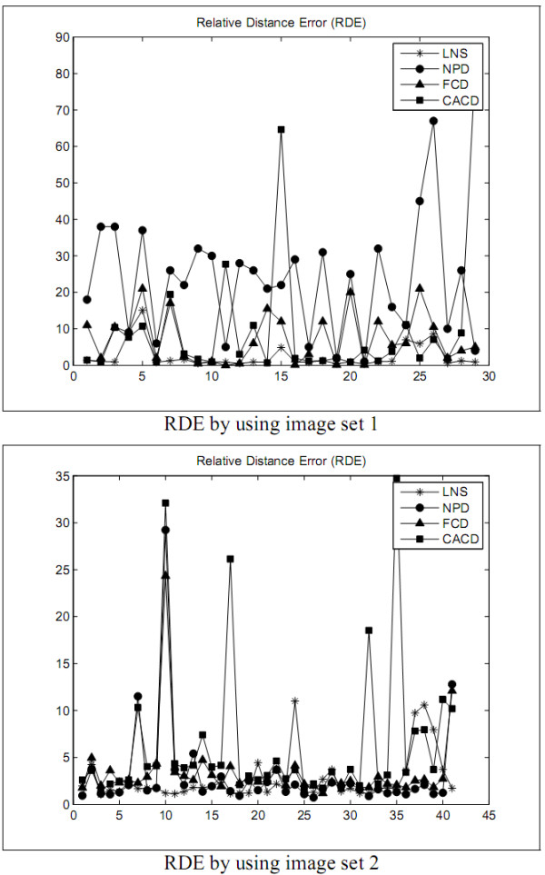
The RDE of the first experiment.
Figure 3.
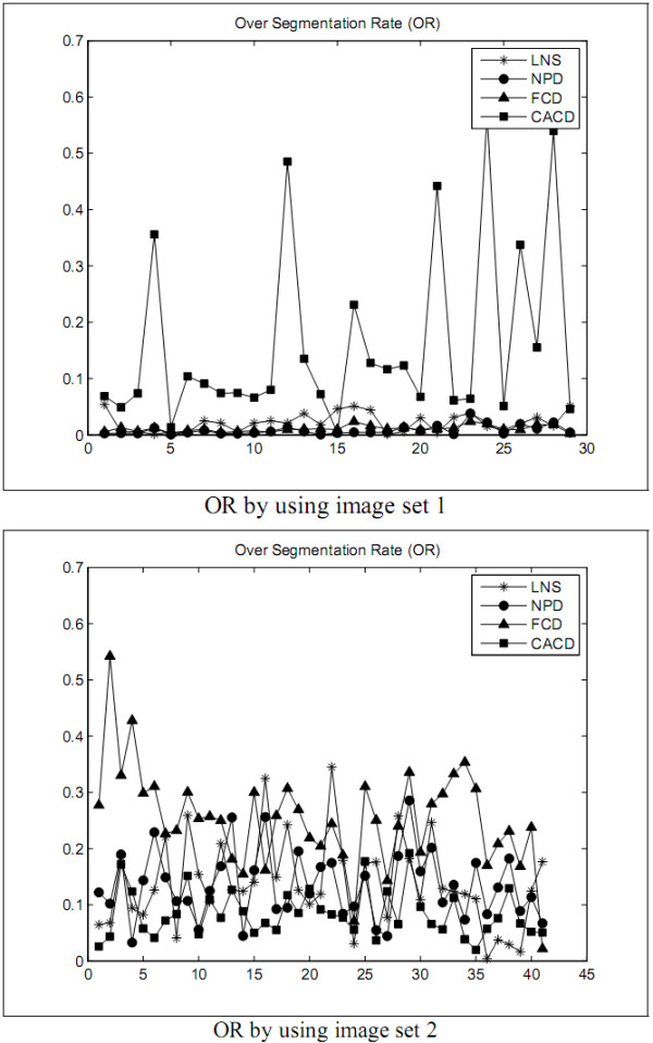
The OR of the first experiment.
Figure 4.
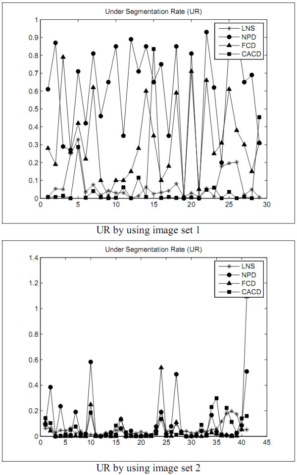
The UR of the first experiment.
Figure 5.
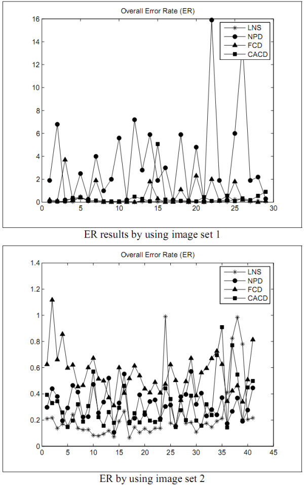
The ER of the first experiment.
Table 1.
The average segmentation errors by using the images in set 1 of test images
| Error/Method | OR | UR | ER | RDE |
|---|---|---|---|---|
| LNS | 0.028 | 0.064 | 0.105 | 2.080 |
| NPD | 0.008 | 0.596 | 3.379 | 22.772 |
| FCD | 0.009 | 0.317 | 0.737 | 8.091 |
| CACD | 0.161 | 0.694 | 0.398 | 10.068 |
Table 2.
The average segmentation errors by using the images in set 2 of test images
| Error/Method | OR | UR | ER | RDE |
|---|---|---|---|---|
| LNS | 0.134 | 0.051 | 0.23 | 2.683 |
| NPD | 0.134 | 0.086 | 0.32 | 3.029 |
| FCD | 0.252 | 0.061 | 0.545 | 3.432 |
| CACD | 0.084 | 0.059 | 0.317 | 6.354 |
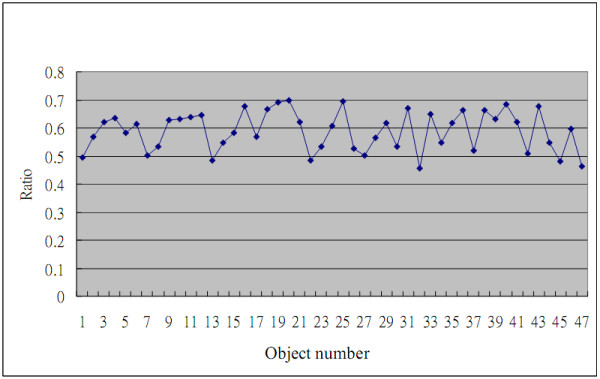
The second experiment is designed to scrutinize the performance of the LC method in splitting the leukocyte nuclei into lobes. The LC method is used to detect whether a leukocyte nucleus comprises more than one lobe or not, and then to separate those seemed-multi-lobe image of the nucleus into clear lobes. If the area ratio R of the leukocyte nucleus to its MBR is less than a threshold rA, the leukocyte nucleus is considered to be the nucleus containing more than one lobe. The R's of 47 leukocyte nuclei to their MBRs is shown in Figure 6, where the 47 leukocyte nuclei have to be split further. The curve in Figure 6 displays that its R is almost less than 0.7 for each leukocyte nuclei. Therefore, in this experiment, rA is set to 0.7.
Figure 6.
The area ratio R of a nucleus to the related MRC.
The LC method is used to split the leukocyte nuclei into lobes with rA = 0.7. In this experiment, the biological expert figures out 223 leukocyte nucleus lobes in the 29 test images. The leukocyte nuclei were split into lobes and counted that there are 186 leukocyte nucleus lobes in the 29 test images. The accuracy rate of 83.41% resulted from counting the leukocyte nucleus lobes on the blood smear images by the LC method.
Discussion
The first experimental results show that the LNS method is inferior to the NPD and FCD methods but worse than the CACD method in OR by using the images in set 1 as test data. With set 2 as test data, the LNS method performed better OR than the CACD method but worse than the FCD method, and as excellently as the NPD method. The results of this experiment revealed that the LNS method resulted in much better UR, ER, and RDE and is much less sensitive to the variation of images.
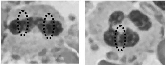
In the primary stage of a continued "right shift" (increasing the number of lobes), a leukocyte nucleus was twisted and slightly indented, such as the regions indicated by the black dashes in Figure 7. The experimental results show that LC method can provide a good lobe split for most leukocyte nuclei, except the leukocyte nuclei with a slight indentation.
Figure 7.
The white blood cell with obscure fracture.
Conclusions
Insensitive to the variance of images, the LNS method functioned well to isolate the leukocyte nuclei from a blood smear image with much better UR, ER, and RDE. The presented LC method is capable of splitting leukocyte nuclei into lobes. The experimental results illuminated that both methods can give expressive performances. In addition, three advanced image processing techniques were proposed as weighted Sobel operator, GDW, and GBPD. In a weighted Sobel operator, a user can give the most suitable rs to satisfy his requirement. A bigger rs is required for the user to accentuate the objects with a more definite contour. To highlight the objects with an indistinct contour, a smaller rs has to be assigned. GDW can not only enhance the object's contour, but also suppress the noise's contour. GBPD was used to determine the optimal parameters that were used in LNS method.
Methods
In this study, a Leukocyte Nuclei Segmentation (LNS) method was proposed to automatically extract the leukocyte nuclei region from a blood smear image. The LNS method consists of two stages: Object Contour Detection and Leukocyte Nuclei Segmentation. A blood smear image is the image mixture of possible leukocytes, erythrocyte cells, platelets, leukocyte nuclei, and noise. The goal of the object contour detection stage is to locate all the objects on the image. At the leukocyte nuclei segmentation stage, leukocyte nucleus objects were then filtered out based on the gray-level intensities and the sizes of the objects obtained at the object contour detection stage.
Object Contour Detection
During the object contour detection stage, there are six approaches: preprocessing, weighted Sobel operator, gradient direction weight enhancer, candidate contour pixel detecting, thinning and spur trimming, and region combination. The flowchart of LNS method is shown in Figure 8; this section will introduce each of these approaches in detail.
Figure 8.
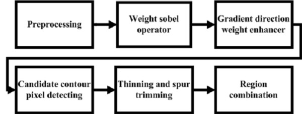
The flowchart of leukocyte nucleus segmentation processing.
Preprocessing
The blood smear may be stained by different color dyes. To avoid being influenced by dye color, all blood smear images were first transformed into gray-level. In order to diminish the variation of images, the pixels' gray-level intensities of a blood smear image I0 were then stretched to the full 0 to 255 range. Let I0(x, y) (resp. Ip(x, y)) be the pixel located at the coordinates (x, y) on I0 (resp. Ip), and max as well as min the maximal and the minimal gray-level intensities of all the pixels in I0, respectively. I0 is then transformed into Ip by to reduce the variation among all different images.
Weighted Sobel Operator
An edge generally corresponds to a set of strong illumination gradients. Sobel operator [14] is one of the simplest and most effective gradient computation methods. LNS method will employ Sobel operator to calculate the gradients of the pixels in Ip. Two 3×3 convolution masks shown in Figure 9 are employed in Sobel operator. We call W(x, y) a corresponding window of Ip(x, y) where Ip(x, y) is located at the center of W(x, y) and W(x, y) consists of m×m pixels. Ip(x ± x', y ± y') are the pixels in W(x, y) for and .
Figure 9.
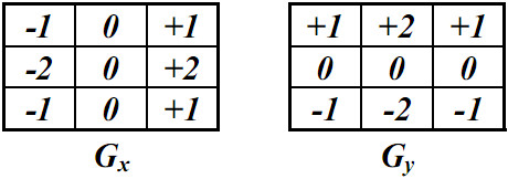
Two convolution masks of Sobel operator.
Let the corresponding window W(x, y) of Ip(x, y) consist of 3 × 3 pixels. The Sobel operator defines the gradient g(x, y) of Ip(x, y) as the following:
| (7) |
| (8) |
and
| (9) |
where ⊗ is the operator of convolution.
Different users prefer either to highlight the gradients of the pixels with high gradients, or to enhance the gradients of the pixels with low gradients. To solve these problem caused by human preference, a Weighted Sobel Operator (WSO) was then proposed by the authors. Let gM and gm be the maximal and minimal ones of all the pixel gradients in Ip. This weighted sobel operator assigns to the gray-level intensity of the pixel Ig(x, y) located at the coordinates (x, y) in Ig, where rs is a given constant. Hence, Ig can be a gray-level image regarding the gradients of the pixels in Ip.
Given a big rs (i.e. rs>1), WSO will enhance the pixel with a high gradient but suppress the pixel with low gradient obtained by Sobel operator. Contrarily, when given a small rs (i.e. rs<1), it will inhibit the pixel with high gradient but highlight the pixel with low gradient computed by Sobel operator. The gradients obtained by the weighted Sobel operator with different rs are shown in Figure 10. A generic algorithm was then used to decide the optimal value of rs later.
Figure 10.
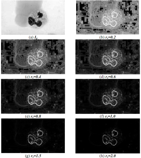
The gradients obtained by the weighted Sobel operator with different rs.
Gradient Direction Weight Enhancer
Given a smaller rs, the weighted Sobel operator can make the object contour more obvious but also raising the gradient of noise. A GDW (Gradient Direction Weight) Enhancer was proposed in this paper to lower the gradient of noise contour and enhance the gradient of object contour. The gradient directions of the pixels near the object contour are usually almost perpendicular to the direction of the object contour. In microscopic viewpoints, a small object contour segment is close to one straight line. For example in Figure 11(a), the line L is an object contour segment and the arrows are the gradient directions of the pixels near the object contour segment. Moreover, these gradient directions near a noise contour are shown in Figure 11(b). Based on this property, a GDW enhancer was proposed to simultaneously brighten the gradient of the object contour and to suppress the gradient of the noise contour.
Figure 11.
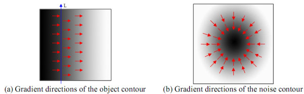
The difference of contour gradient directions of objects and noises.
The gradient direction of a pixel I0(x, y) can be defined as , where ΔGx(x, y) and ΔGy(x, y) can be computed by Formula (7) and (8). Assume that one object contour segment L passes through Ip(x, y), and the angle of L inclined to the horizontal axis is θL. The GDW enhancer first estimates θL, which is supposed to be close to one of 0°, 45°, 90°, and 135°. Let WG be a corresponding window of Ip(x, y) composed of mG×mG pixels and divided into two equal regions according to the four different possible directions of L at angles 0°, 45°, 90°, and 135° with respect to the horizontal line. Four different partitions where mG = 7 are shown in Figure 12. The black dots and the white dots signify the black region and the white region, respectively. The partitions in Figure 12 was named θ-partitions for θ = 0°, 45°, 90°, and 135°, respectively. For each θ-partition, dθ = |cb-cw| was calculated, where cb and cw are the average gray-level intensities of the black and white regions, respectively. Here, the estimated angle θL of L is defined as and the GDW of Ip(x, y) as |sin(θL-θg)|.
Figure 12.
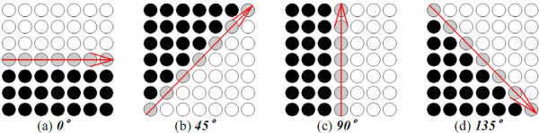
Four θL-partitions of W.
As |θL-θg| is closer to 90° and Ig(x, y) is bigger, the probability of I0(x, y) located at the object contour is higher. Therefore, with the GDW enhancer, can be assigned to the gray-level intensity of IG(x, y) for generating a new gray-level image IG, where rG is a given constant. The optimal constant rG will be decided by a genetic algorithm. The images before and after the GDW enhancer processing are shown in Figure 13.
Figure 13.
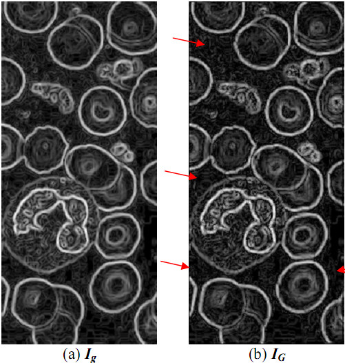
The images before and after processed by GDW.
Candidate Contour Pixel Detecting
The gray-level intensity of IG(x, y) represents the possibility of I0(x, y) to be an object contour pixel. To successfully cut off objects from I0 following GDW enhancer approach processing, given an adaptive threshold to isolate the possible object contour pixels is a pre-requisite. Given a bigger threshold, higher contrast edges may be detected but some desired edges with low contrast may be overlooked. On the contrary, lower contrast edges may be gleamed given a smaller threshold, but more noise edges may probably be collected simultaneously. One of the commonly used threshold decision making methods, Otsu's method [15], is thus utilized in LNS method to specify the threshold Th. Otsu's method exhaustively searches for the threshold t* that minimizes the within-class variance, defined as a weighted sum of variances of two classes:
| (10) |
where weight pi is the probability of a pixel in the i-th class separated by a threshold t and the variance of pixels' gray-level intensities in the i-th classes.
In LNS method, each pixel IG(x, y) in IG was swept to generate a binary image Ib. The threshold t* was then applied to obtain an appropriate threshold t*×rt for better candidate object contour extraction. The optimal rt couldbe obtained by a genetic algorithm which will be introduced later in this paper. If IG(x, y) is greater than or equal to t*×rt, then 1 was assigned to Ib(x, y); otherwise, a value of 0 would be assigned. The pixel Ib(x, y) with 1-bit is called a candidate object contour pixel. One IG and its corresponding Ib are demonstrated in Figure 14.
Figure 14.
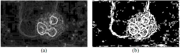
IG and its corresponding Ib.
Thinning and Spur Trimming
Noises in an image or the exquisite vein, and the pixels at the vicinity of object contour may cause false edges. The expected thickness of an object contour would be one-pixel. In this paper, the Hit-and-Miss Transform-based Skeletonization (HMTS) algorithm [6] is used to reduce the object contour in the thickness of one pixel. The eliminated candidate edge pixels were named as redundant-edge pixels and the remaining candidate edge pixels as true-edge pixels by the authors.
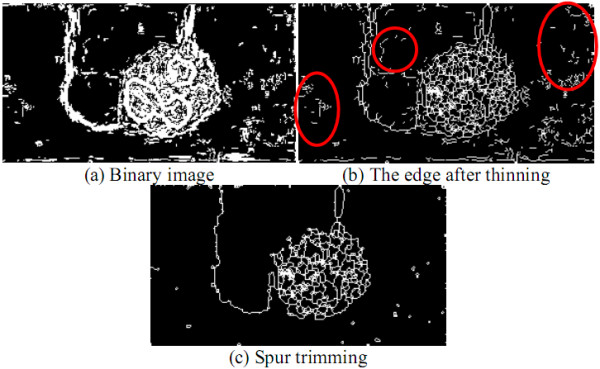
Thereafter, the region detecting approach takes the HMTS algorithm [12,14] to reduce the object contour thickness in one pixel. Let each pixel Ib(x, y) in Ib correspond to a window Wt(x, y), where Wt(x, y) consists of 3×3 pixels and Ib(x, y) is the central pixel of Wt(x, y). Wt(x, y) was compared with each of the eight structuring elements in HMTS algorithm shown in Figure 15, where the gray pixels stand for the don't-care pixels (A don't-care pixel may be a 1-bit pixel or a 0-bit pixel). Wt(x, y) is matched if the positions and values of 1- and 0-bits on one structuring element are completely the same as those on Wt(x, y), regardless of don't-care pixels. When Wt(x, y) is matched, Ib(x, y) is changed into 0. This procedure was repeated until no more thinning needs to be performed in this algorithm. The HMTS algorithm has been performed to cut off the redundant-edge pixels, resulting in single-pixel edge thickness. The result after running the thinning operation is shown on Figure 16(b).
Figure 15.
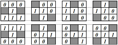
Eight structuring elements for thinning.
Figure 16.
The results after thinning and trimming spurs.
After being processed by HMTS method, some small spurs may appear on the skeleton, which are not the desired edges. Therefore, a trimming spur algorithm is required to remove the spurs. The procedure of the trimming spur algorithm [13] is exactly the same as that of above thinning algorithm except for the eight structuring elements in Figure 15, which are replaced by those in Figure 17. The result obtained by the trimming spur algorithm on the image in Figure 16(b) is shown in Figure 16(c). Let Ie be the binary contour image, which has been processed by the trimming spur algorithm.
Figure 17.
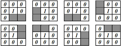
Eight structuring elements for trimming spurs.
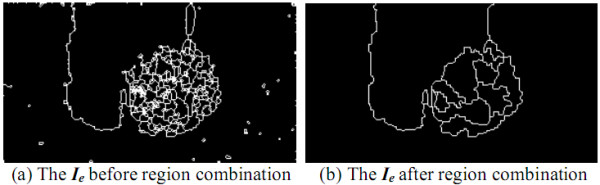
Region Combination
Since the cytoplasm and nuclei of leukocytes are frequently uneven, a nucleus may be segmented into several small regions after the previous image processing. In addition, some noises may still exist on the blood smear image. Therefore, some regions in Ie must be combined into one or be removed. Let B and B' be two different regions on Ip, the contours of which are marked on Ie, where B' is adjoining to B and B' has the minimal gray-level intensity difference from B.
Let A and A' be the numbers of pixels in B and B' respectively, and C and C' be the average gray-level intensities of all the pixels in B and in B', respectively. As one of the following criteria is satisfied, B can be combined to B':
1) A ≤ t1;
2) A ≥ t2, |C - C'| ≤ t3, and B is located at the image boundary of Ip (a part of B is not in I0);
3) A ≥ t4, |C - C'| ≤ t3, and B is not located at the image boundary of Ip,
where t1, t2, ..., t4 are four given thresholds. The result after combining the segmented regions in Figure 18(a) is shown in Figure 18(b).
Figure 18.
The result after region combination.
Leukocyte Nuclei Segmentation
After the regions combination, every closed curve in Ie represents an object. There may be many kinds of objects, like erythrocytes, the cytoplasts and nuclei of leukocyte, platelets, and noise in a blood smear image. This stage is intended to filter out the objects of leukocyte nuclei from Ie. The leukocyte nucleus is usually darker than the other blood cell's. The cytoplasts of basophil and lymphocyte are much darker than those of the erythrocyte cells, and the cytoplasts of other leukocytes are brighter or a little darker than those of the erythrocytes. The area of platelets is much smaller than that of the lymphocyte nuclei. Based on these properties, the leukocyte nuclei can be filtered out.
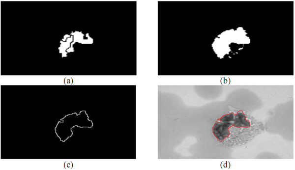
Let Cave be the average gray-level intensity of all the pixels in all the objects indicated by Ie. Since the leukocyte nuclei is darker than others, if the average gray-level intensity of an object is smaller than or equal to T = Cave×rr, then this object is regarded as a leukocyte nuclei, where rr is a given constant. Through the above processing, the filtered-out leukocyte nuclei for rr = 0.7 is shown in Figure 19(a). This paper will use a genetic algorithm to obtain the optimal rr. The textures of leukocyte cytoplasts and nuclei are often uneven. For segmenting the leukocyte nuclei more accurately, this stage refines the contours on Ie. If a pixel inside a leukocyte nuclei contour in Ie with gray-level intensity larger than Cave, then this pixel is assigned to a non-leukocyte nuclei pixel. If a pixel is outside the leukocyte nuclei contours and the minimal distance between the pixel and the contour indicated in Ie is less than 5 pixels and its gray-level intensity smaller than or equal to T, the pixel is considered a leukocyte nuclei pixel.
Figure 19.
The segmentation results obtained in the leukocyte nuclei segmentation stage.
Some objects in Ie may be platelets or noise, which are generally smaller than the lobes of leukocyte nucleus; the region with a large area in Ie is always a white blood cell or consists of several erythrocytes overlapping together. According to this property, the segmented objects were sorted according to their sizes. Let Am be the area of the median object in size. Sized less than t5×Am, the object was removed by the LNS method. The results after refining the contours on the image in Figure 19(a) are shown in Figure 19(b); the results after removing the small objects are shown in Figure 19(c); Figure 19(d) is the segmented contours.
A leukocyte nucleus probably consists of several nuclei. If the contours of two nuclei are very close, both nuclei are considered the same leukocyte nuclei. As the sizes of two objects are less than Am and the distance of two closest pixels between the contours on the two nuclei is less than or equal to , both leukocyte nuclei are considered the same.
Lobe Counting
The shape of the leukocyte nucleus is one of the most important features in determining the type of the leukocyte nucleus. The number of lobes can be used to describe the phenomenon of neutrophil right shift. In this section, Lobe Counting (LC) method is presented to count the number of lobes in a leukocyte nucleus indicated in Ie.
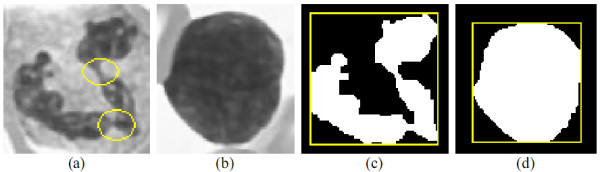
A leukocyte nucleus can be completely encircled by a Minimum Bounding Rectangle (MBR), shown as Figures 20(c) and 14(d). While the contour of the leukocyte nucleus is very crooked and uneven, the ratio R of leukocyte nucleus area to its MBR's is small. If R is less than a threshold rA, the nucleus is considered to comprise more than one lobe and their lobes need cutting off, i.e. the nucleus in Figure 20(c); otherwise, the nucleus is considered to contain only one lobe, and it is unnecessary to split the nucleus as shown in Figure 20(d).
Figure 20.
The leukocyte nuclei and their MBR.
Obj_cut(obj)
(1) While obj.#iteration <MAX_#EROSION
(2) Erode object obj
(3) If obj will vanish in next erosion then /* obj will disappear in next erosion operation */
(4) Dilate obj obj.#iteration runs and return the object obj
(5) If obj is not split into some sub-objects then
(6) obj.#iteration = obj.#iteration + 1
(7) Obj_cut(obj) /* continue to run erosion operation */
(8) If obj is split into sub-objects obj1, obj2, ..., objn then
(9) for i = 1 to n
(10) obji.#iteration = 0
(11) Obj_cut(obji) /* continue to run erosion operation */
(12) Dilate obji obji.#iteration runs and return obji
(13) Dilate obj obj.#iteration runs and return obj
A junction between two lobes in a leukocyte nucleus is usually at the contour crooked extremely or at the narrow part of leukocyte nucleus, shown in Figure 20(a). Erosion and dilation operations [6] were applied in the LC method to separate the lobes. Let obj be a nucleus which consists of two parameters, the nucleus of object obj and obj.#iteration. With obj.#iteration, the number of iterations ascends to execute erosion then dilation operation. MAX_#EROSION is the given maximal number of iterations in eroded obj. Algorithm Obj_cut(obj) functions to cut off the lobes from obj with the structuring element in Figure 21 for erosion and dilation operations.
Figure 21.
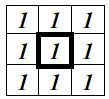
The structuring element of erosion and dilation operation.
In an Obj_cut(obj), after executing erosion operation on object obj, obj may disappear, not be split into some sub-objects, or be split into some sub-objects. Lines 3 and 4 handle the case where obj will disappear in the next erosion operation. Lines (5) to (7) deal with the obj that is not split into some sub-objects. If obj is cut into some sub-objects, each sub-object will be split continually. Lines (8) to (12) perform it.
Figure 22(b) is the contour of a leukocyte nucleus detected by the LNS method from the image in Figure 22(a). The R = 0.56 of the object obj indicated by a arrow in Figure 22(b) is less than rA (in this example, rA is set to 0.7), so obj needs splitting. Figure 22(c) shows the obj. Until the fifth run in eroding obj, obj is split into two sub-objects obj1 and obj2, displayed in Figure 22(d). Then, obj1 is repeatedly split. After two eroding runs, obj1 is separated into two objects obj11 and obj12, demonstrated in Figure 22(e). Obj_cut() continually severs obj11. Figure 22(f) is the obj11 after one eroding run. After two eroding runs, obj11 will disappear. Hence, the algorithm runs dilation operation once on obj11 in Figure 22(f); Figure 22(g) is the result of this run. Next, Obj_cut() tries to split obj12. Since obj12 will disappear after executing one erosion operation, no erosion and no dilation will be executed on obj12. Afterward, Obj_cut() goes to erode obj2. obj2 vanishes after running erosion twice on obj2. Figure 22(h) is the obj2 after applying erosion operation once to obj2. Therefore, Obj_cut() runs dilation operation once on obj2; Figure 22(i) shows the final result of running Obj_cut() on original obj.
Figure 22.
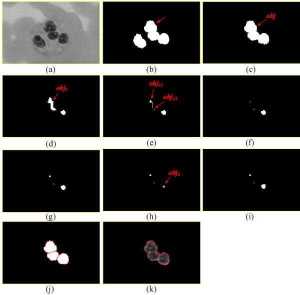
The procedure severing out the lobes from an object.
After executing Obj_cut(obj), some pixels in the original obj may not appear in the divided objects. Each of the unclassified pixels will be assigned to one of the divided objects. The LC method will compute the distance between every unclassified pixel p and each contour pixel in the divided objects and assigns p to the divided object, one of whose contour pixels is closest to p. Afterwards, Figure 22(i) is converted into Figure 22(j). Figure 22(k) is the original image drawn on the divided object contours.
Genetic-Based Parameter Detector (GBPD)
The performance of the LNS method is deeply affected by the values of rs, rG, rt, rr, t1, t2, t3, t4, t5, and t6. In this paper, a genetic-based parameter detector (GBPD) is employed to determine the most suitable values of rs, rG, rt, rr, t1, t2, t3, t4, t5, and t6.
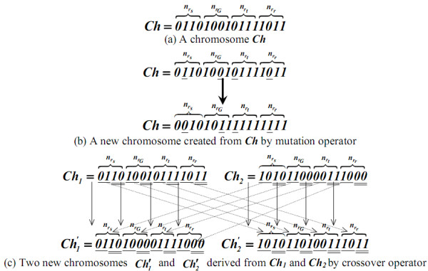
A genetic algorithm (GA) [16] is a heuristic optimization method in which the set of possible solutions is considered a population of individuals. The adaptation degree of an individual to its environment is specified by its fitness. The coordinate of an individual in the search space is represented by a chromosome. A gene is a subsection of a chromosome that encodes the value of a single parameter being optimized. A genetic algorithm derives from evolutionary theory, so that, given a certain population, only the individuals adapting well to their environment can survive and transmit their characteristics to their descendants. Basically, a genetic algorithm consists of three major operations: selection, crossover, and mutation. Selection evaluates all individuals and only those most adaptable to their environment can survive. Crossover recombines the genetic material of two individuals to form new combinations with the potential for a better performance. Mutation induces changes in a small number of chromosomal units to maintain sufficient population diversity during the optimization process.
GBPD utilizes a binary string, concatenated by ten binary substrings ss, sG, st, sr, s1, s2, s3, s4, s5, and s6, respectively comprised of , , , , n1, n2, n3, n4, n5, and n6 binary bits, to represent a chromosome Ch. ss, sG, st, sr, s1, s2, s3, s4, s5, and s6 are designated to describe the corresponding values of rs, rG, rt, rr, t1, t2, t3, t4, t5, and t6. For each chromosome Ch, rs, rG, rt, rr, t1, t2, t3, t4, t5, and t6 are encoded as
where , , , , , , , , , and are the number of 1-bits in ss, sG, st, sr, s1, s2, s3, s4, s5, and s6, respectively.
GBPD applies the accumulated historic data to train the most appropriate rs, rG, rt, rr, t1, t2, t3, t4, t5, and t6 via a genetic algorithm. The manually drawn leukocyte nuclei contours are considered a collection of ground truths. GBPD uses the average relative foreground area error (RAE) as the measure of fitness of a chromosome based on the rs, rG, rt, rr, t1, t2, t3, t4, t5, and t6 encoded by the chromosome.
GBPD first randomly generates N chromosomes, each consisting of , , , , n1, n2, n3, n4, n5, and n6 binary bits. To evolve the best solution, the genetic algorithm repeatedly executes mutation, crossover, and selection operations until the relative fitness of the reserved chromosomes are similar.
In mutation operation, for each of the N reserved chromosomes, GBPD uses a random number generator to specify one bit b for each of ss, sG, st, sr, s1, s2, s3, s4, s5, and s6. b is then replaced by ¬b to generate a new chromosome, where ¬ signifies the operator "NOT."
In crossover operation, similarly a random number generator is used to designate N' pairs of chromosomes from the N reserved chromosomes. Let Ch[i..j] be the substring consisting of the ith to jth bits in Ch, S = {0, , , , , n1, n2, n3, n4, n5, n6} be an ordered set, and ei be the ith element in S. For each chromosome pair (Ch1, Ch2), the genetic algorithm concatenates
into a new chromosome, and concatenates
into another new chromosome, where ⊗ represents a concatenation operator.
In selection operation, N optimal chromosomes are selected from the N chromosomes reserved in the previous iteration and N as well as 2×N' chromosomes created in the mutation and crossover operations according to their fitness. Three major operations (mutation, crossover, and selection) need to be continuously performed until the related fitness of the reserved N chromosomes is very close or the number of iterations is equal to the specified maximum number of generations.
Figure 23(a) shows a chromosome Ch with = 4, = 4, = 4, and = 4; derived from Ch, rs = 0.2, rG = 1.6, rt = 0.3 and rr = 0.3. For convenience to describe, in this example, we assure that Ch only consists of four substrings ss, sG, st, and sr. Figure 23(b) demonstrates a new chromosome created from Ch by a mutation operator, where the bits underlined are the randomly selected bits b's. Two new chromosomes and generated from the two chromosomes Ch1 and Ch2 through the crossover operator as shown in Figure 23(c).
Figure 23.
An example for GBPD.
Authors' contributions
DCH and YKC conceived the study. DCH designed the approach and performed the computational analysis with YKC, ZHZ, and KDH. DCH and YKC supervised the work and tested the program. DCH, YKC, and MHT wrote the manuscript. MHT prepared the samples and collected the data together with ZHZ and KDH. MHT contributed analyzing experimental studies. All authors read and approved the final manuscript. YKC and MHT contributed equally and are the first authors as well as listed in alphabetical order.
Contributor Information
Yung-Kuan Chan, Email: ykchan@nchu.edu.tw.
Meng-Hsiun Tsai, Email: mht@nchu.edu.tw.
Der-Chen Huang, Email: huangdc@cs.nchu.edu.tw.
Zong-Han Zheng, Email: s9556040@cs.nchu.edu.tw.
Kun-Ding Hung, Email: phd9505@cs.nchu.edu.tw.
Acknowledgements
We would like to thank the anonymous reviewers for all their very helpful comments that improve the quality of this paper. This study was supported in part by National Chung Hsing University, Taichung, Taiwan, under grant 995031 for YKC.
References
- Timby BK, Smith NE. Introductory Medical-Surgical Nursing. Nine. Lippincott Williams & Wilkins; 2006. [Google Scholar]
- Human Physiology and Anatomy. Blood Cell Histology. http://www.unomaha.edu/hpa/blood.html
- Bagby GC. In: Cecil Medicine. 23. Goldman L, Ausiello D, editor. Philadelphia, Pa: Saunders Elsevier; 2007. Leukopenia and Leukocytosis. [Google Scholar]
- Scientific Psychic. The Hematologist. http://www.scientificpsychic.com/mind/whitecells.html
- Bailey SC, Head JF, Greengard O. "Neutrophil Maturation and Hypersegmentation Promoted in Normal Bone Marrow by a Carcinoma-Elaborated Protein Factor,". American Journal of Hematology. 2006;31(3):159–165. doi: 10.1002/ajh.2830310304. [DOI] [PubMed] [Google Scholar]
- Baxes GA. Digital Image Processing: Principles and Applications. New York: John Wiley & Sons; 1994. [Google Scholar]
- Theera-Umpon N, Dhompongsa S. "Morphological Granulometric Features of Nucleus in Automatic Bone Marrow White Blood Cell Classification,". IEEE Transactions on Information Technology in Biomedicine. 2007;11(3):353–359. doi: 10.1109/TITB.2007.892694. [DOI] [PubMed] [Google Scholar]
- Pingkum Y, Zhou X, Shah M, Wong STC. "Automatic Segmentation of High-Throughput RNAi Fluorescent Cellular Images,". IEEE Transactions on Information Technology in Biomedicine. 2008;12(1):109–117. doi: 10.1109/TITB.2007.898006. [DOI] [PMC free article] [PubMed] [Google Scholar]
- Tang C, Ewert B. "Automatic Tracking of Neural Stem Cells,". Proceedings of WDIC2005, Brisbane, Australia. 2005. pp. 61–66.
- Hamghalam M, Motameni M, Kelishomi AE. "Leukocyte Segmentation in Giemsa-stained Image of Peripheral Blood Smears Based on Active Contour,". International Conference on Signal Processing Systems. 2009. pp. 103–106. full_text.
- Liu J, Leong TY, Chee KB, Tan BP, Shuter B, Wang SC. "Set-Based Cascading Approaches for Magnetic Resonance (MR) Image Segmentation (SCAMIS),". AMIA Annual Symposium proceedings. 2006. pp. 504–508. [PMC free article] [PubMed]
- Gonzalez RF, Wintz P. Digital image processing. 3. Addison-Wesley; 1992. [Google Scholar]
- Yang-Mao SF, Chan YK, Chu YP. "Edge Enhancement Nucleus and Cytoplast Contour Detector of Cervical Smear Images,". IEEE Transactions on Systems, Man, and Cybernetics-PART B: Cybernetics. 2008;38(2):353–366. doi: 10.1109/TSMCB.2007.912940. [DOI] [PubMed] [Google Scholar]
- Gonzalez R, Woods R. Digital image processing. Englewood Cliffs, NJ: Prentice-Hall; 2002. [Google Scholar]
- Otsu N. "A Threshold Selection Method from Gray Level Histogram,". IEEE Transactions on Systems, Man, and Cybernetics - B. 1978;8(1):62–66. doi: 10.1109/TSMC.1978.4309832. [DOI] [Google Scholar]
- Man KF, Tang KS, Kwong S. Genetic Algorithms: Concepts and Designs. Springer-Verlag, New York; 1999. [Google Scholar]