Electrospinning has been gaining increasing popularity in the fabrication of engineered tissue scaffolds due to its ability to produce nano to micro scale fibrous sheets. Many investigators have attempted to apply various degrees of control to this process in order to produce fiber meshes with more predictable patterns. These attempts have largely been limited to controlling fiber alignment and have fallen into two categories: physical manipulation of the fibers by pulling them into alignment using a rapidly spinning mandrel[1–3] or manipulation of the electric field during fabrication.[4, 5]
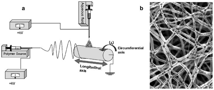
To fully quantify the structure of native tissues and engineered fibrous scaffolds, a novel image analysis technique[6] was recently developed to quantify fiber intersections (number, position and density), connectivity distribution, and fiber angle distribution (Fig 1b). This technique was utilized in conjunction with novel fabrication methods and comprehensive mechanical characterization to advance our understanding of how fiber network topology affects meso-scale mechanical properties of electrospun scaffolds. Specifically, two previously unevaluated fabrication modalities were utilized to induce controlled alterations in fiber network topology: (1) variation of collecting mandrel translation velocity, and (2) concurrent electrospraying of cell culture medium with or without cells or rigid particulates to emulate the maximum possible micro-inclusion stiffness.
Figure 1.
a) Schematic of the fabrication technique. Aqueous fluid indicates cell culture medium with or without a cell suspension. b) Representative SEM micrograph of dry PEUU overlaid by skeletonization of fiber topography generated by the image analysis algorithm.
The experimental setup adopted in the current study was similar to that described previously.[7, 8] Briefly, a solution of poly(ester urethane urea) (PEUU) was fed through a charged capillary located horizontally from a grounded mandrel (Figure 1a). The mandrel was rotated at 266 rpm (~8 cm/s tangential velocity) and rastered along its rotational axis at 0.3, 1.5, 3 or 30 cm/s. PEUU was electrospun dry (with no further modifications to the process) or “wet” by concurrently electrospraying cell culture medium onto the target from a perpendicular orientation to the polymer stream above the mandrel. The effect of cell and particulate inclusion into the fiber scaffold matrix was studied by electrospraying the same medium containing a suspension of a known concentration of either vascular smooth muscle cells or polystyrene microspheres into the cell culture medium. Cells were electrosprayed at concentrations of 2 and 6 million/mL, and microspheres were electrosprayed at 7 million/mL. Scaffolds were evaluated using biaxial mechanical testing in conjunction with structural analysis using a custom algorithm[6].
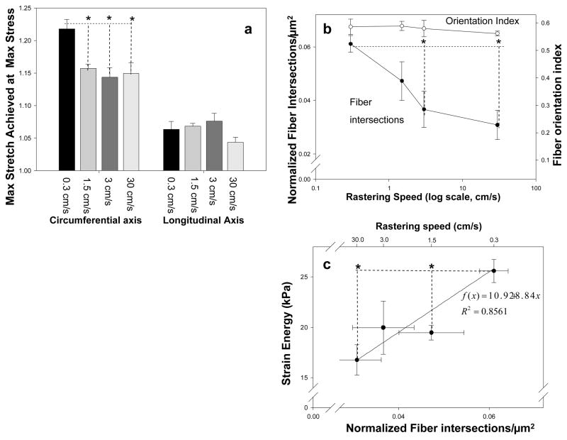
No variations in electrospun scaffold processing studied in this work produced significant change in mass fraction of polymer within the constructs (supplemental Table 1). Increasing the rastering velocity above 0.3 cm/s while keeping all other variables constant appeared to produce a modest stiffening (p<0.001) of the circumferential axis, perpendicular to the axis of raster (Figure 2a). Image analysis revealed a pronounced decrease in fiber intersections at rastering velocities above 0.3 cm/s (p<0.01) in a pattern reminiscent of the stiffening observed in the circumferential axis of the same constructs. This occurred without any significant change in the fiber orientation index (Figure 2b). Consistently, higher strain energy was observed in specimens processed under lower rastering speeds and, consequently, higher fiber intersection densities (Figure 2c). None of the remaining architectural features (fiber angle distribution, connectivity, fiber diameter) identified by the image analysis algorithm demonstrated significant differences between groups.
Figure 2.
a) The effect of increased rastering speed on dry ePEUU biaxial mechanical properties. b) The effect of increasing rastering speed on fiber orientation and normalized fiber intersection density c) The relationship between a fabrication parameter (rastering speed, top x-axis), a structural measure (fiber intersection density, bottom x-axis), and mechanical response (strain energy, y-axis). * indicates statistically significant difference (p<.05)
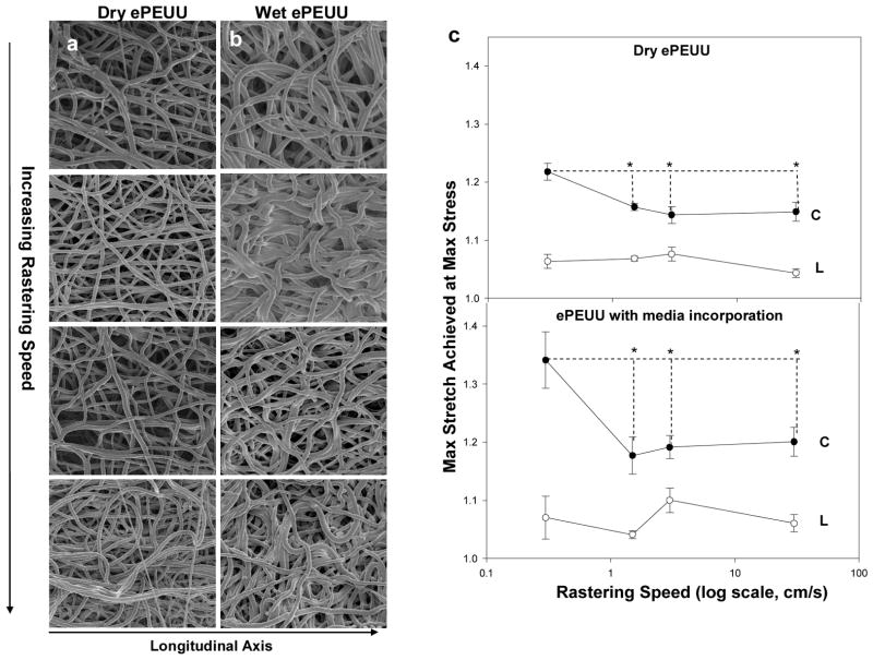
The inclusion of cell culture medium into the construct resulted in a dramatic change in scaffold microarchitecture (Figure 3a,b). Wet ePEUU qualitatively appeared to possess a greater degree of undulation, bundling, and looping that was less common in the ‘dry’ electrospun samples. Unlike dry electrospinning, structural analysis of these scaffolds demonstrated no significant difference in fiber intersection density over the rastering speeds studied (supplemental Figure 1; p=0.117, 0.3 to 30 cm/s rastered groups). Fiber orientation did not differ significantly from that found in dry ePEUU. Faster rastering speeds during fabrication were associated with pronounced stiffening in the circumferential axis (p<0.001) (Figure 3c). Additionally, strain energies in this group did not differ significantly from those that characterized the dry ePEUU groups (p=0.382, data not shown). It can also be observed that introduction of culture medium alone only affected the mechanical response of ePEUU at the lowest rastering speed studied (p<0.001).
Figure 3.
(a,b) Qualitative depictions of fiber microarchitecture of both dry and wet ePEUU scaffolds in descending order according to rastering speed, with 0.3 cm/s on the top and 30 cm/s on the bottom. c) Comparison of the mechanical response of dry and wet ePEUU across rastering speeds. (C indicates the circumferential axis, whereas L indicates longitudinal axis) *indicates statistically significant difference
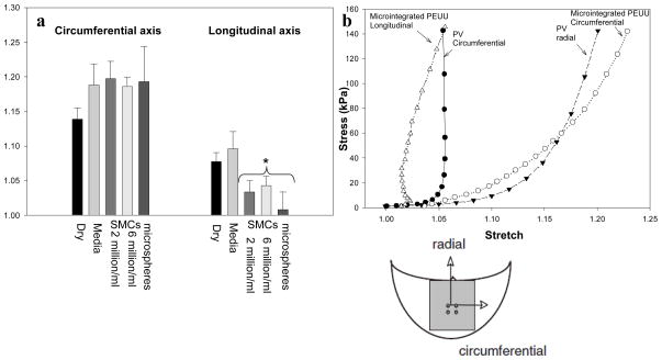
Inspection of SEM micrographs (supplemental Figure 2) demonstrated that smooth muscle cells or microspheres concurrently electrosprayed into the ePEUU scaffolds become an integral part of the fibrous network, in contact with multiple fibers. Interestingly, these particulates produced a significant increase in scaffold mechanical anisotropy beyond that found in either dry or wet ePEUU at the same rastering speed (Figure 4a). This appears to be related to a stiffened longitudinal direction of the construct. In contrast, increasing the concentration of cells within the electrospray suspension did not affect the mechanical anisotropy, nor did replacing the cells with rigid polystyrene microspheres. No significant differences were observed between any micro-architectural parameters between microsphere integrated and wet ePEUU. More importantly, it was shown that when cells are integrated into an electrospun construct in conjunction with the adoption of slow rastering velocity (0.3 cm/s) the resultant construct possesses a mechanical response that resembles highly anisotropic soft tissues (Figure 4b).
Figure 4.
a) The change in biaxial mechanical response resultant from integrated particulates within ePEUU fiber matrix. Rastering speed during fabrication was 3.0 cm/s * indicates statistically significant difference from both ‘dry’ and ‘wet’ groups. b) Combining slow rastering with concurrent cell electrospraying produces a construct with mechanical anisotropy reminiscent of the native porcine pulmonary valve. (plots not significantly different from each other )
In the present study, we demonstrated that fiber topology and bulk mechanical response can be modulated by altering the net fiber interconnection densities without altering fiber alignment, achieved by translating the cylindrical collecting mandrel along its rotational axis at varying rates. It was further shown that constructs containing high densities of fiber interconnections were associated with higher strain energies and mechanical anisotropy. Fiber topology and bulk mechanical response were further altered through concurrent electrospraying of cell culture medium with or without living cells or rigid particulates during fabrication. It was discovered that a substantially higher degree of fiber intersections, but not fiber alignment, was associated with increased mechanical anisotropy and strain energy. Moreover, both fiber alignment and intersection density have fundamental implications for tailoring scaffold mechanical behavior and can be independently or synergistically applied to better approximate specific macro level native tissue mechanical responses. This knowledge provides additional levels of control at the fabrication level on micro-scale topology and macro-scale mechanical properties.
These studies were made largely possible due to the introduction of a new method imaging method for micro structural analysis. Current image processing techniques [1,9,12] can only quantify fiber angle distribution(s). In contrast, the importance of number and density of fiber intersections, network connectivity, and fiber diameter distributions on scaffold mechanical behavior has been discussed[10, 11]. While it was expected that an increase in rastering speed would further orient the fibers due to physical motion of the mandrel, fiber alignment remained consistent through an order of magnitude increase in rastering speed despite a marked change in mechanical properties (Figure 2a,b). Previous results[1] indicated that an alignment due to increased rotational velocity will stiffen the rotational axis, however this was not significant until the mandrel was rotated at a tangential speed higher than 2 m/s, a much faster rotational velocity than the one presented in this work. This finding suggests that fiber orientation alone does not adequately describe the mechanical response of these electrospun polyurethanes. An exponential decrease in fiber intersections was observed as rastering velocity was increased beyond 0.3 cm/s (Figure 2b). This pattern is reminiscent of the change in circumferential axis compliance observed. Furthermore, fiber intersections were shown to be correlated with strain energy (r2=0.86) (Figure 2c). As all other structural parameters remained comparable (fiber diameter, connectivity, orientation index) across the rastering speeds, it can be speculated that the fiber intersection density is related to and potentially responsible for the observed increase in mechanical anisotropy and strain energy, perhaps through directional restriction of fiber motion. The precise mechanism by which this effect occurs is currently unclear, and should be elucidated through structural deterministic modeling [10–13].
Concurrent electrospraying of cell culture medium onto the depositing scaffold during fabrication also induced a distinct change in scaffold microstructure. This is likely due to an aqueous layer that adhered to the forming scaffold as it rotated, delaying, but not preventing fiber bonding. It would follow that there would be more slack length, which would allow the additional, looping and undulation observed in SEM micrographs (Figure 3a,b). At a rastering speed of 0.3 cm/s, this leads to a more compliant mechanical response, however this appears to be overcome by increasing the rastering speed. It follows logically that the increase in tortuosity might create artifactual fiber intersections at locations where fibers are not actually securely bound together. This is admittedly a limitation with the current analysis, and has an implication in explaining the lack of definitive structural pattern with respect to rastering speed in wet ePEUU images while every mechanical trend observed in dry ePEUU remains consistent.
When the electrosprayed medium is supplemented with particulates or cells, a distinct change occurs in the mechanical response of the scaffold. The microsphere size (10μm) was chosen to be the same approximate physical size as the smooth muscle cells before they spread among the fibers. A consistent pattern of a stiffened longitudinal axis was observed in the mechanical response of particulate integrated constructs (Figure 4a). A potential interpretation of this phenomenon is that particulates could serve as bridges connecting fibers to an extent beyond that which would be found with fiber intersections only. Following this assumption, particulates and cells would act as additional fiber bonding increasing the effective fiber intersection density and consequently raising the level of mechanical anisotropy. Additionally, previous work in structural modeling for valvular tissue[10] provides insights into the behavior of the longitudinal axis of these materials. In this work, it was observed that in anisotropic fibrous materials, a biaxial mechanical stress state can lead to micro-scale fiber rotations which translates to negative strain in the macro-scale response[10]. This likely contributes to the phenomenon observed in this work and underscores the appropriateness of these scaffolds in the development of engineered heart valve tissues.
The complexity of electrospun scaffold morphology and the consequential difficulties in collecting quantitative structural information, particularly in wet processed ePEUU, imply the clear need for additional studies aiming to consolidate the aforementioned hypothesis. Specifically in this context structural deterministic modeling[11–14] represents an important approach in future studies. Micro-meso architecture based mechanical models might, for instance, be adopted to investigate the influence of fiber intersection density on the material mechanical response.
While work in controlling bulk mechanical properties of electrospun scaffolds have focused on modifying fiber alignment through either electric field manipulation or high rotational velocities, the exact nature of the resulting fiber architectures and their relation to macroscopic mechanical behavior remain elusive. The results of the present study indicate that fiber orientation alone does not adequately describe the mechanical response of elastomeric electrospun scaffolds. Further, fiber alignment and intersection density can be controlled independently, allowing for an additional level of control on scaffold microstructure. Moreover, such control can be applied in conjunction with cell electrospraying to create highly anisotropic cellularized constructs without utilizing high rotational velocities, which are not amenable to the microintegration technique.[7] Rastering was speculated to introduce macro-scale mechanical changes through modification of fiber intersection density. This method of scaffold fabrication was found to be nearly as effective in altering scaffold anisotropy as fiber alignment due to increasing tangential velocities. Practically, wet processing and mandrel rastering can be successfully implemented as tools to reliably modify scaffold microarchitecture without altering fiber alignment.
Experimental
Cell culture
Vascular smooth muscle cells, chosen for their utility in cardiovascular applications, were isolated from Lewis rat aortas and were expanded on tissue culture polystyrene culture flasks using Dulbecco’s modified Eagle medium (DMEM) (Lonza) supplemented with 10% fetal bovine serum and 1% penicillin-streptomycin [15].
Scaffold fabrication and characterization
Poly(ester urethane) urea (PEUU) was synthesized and electrospun as described previously [16] [7, 8]. Briefly, a 12%(w/v) solution of PEUU in 1,1,1,3,3,3-hexafluoroisopropanol (Oakwood Products, Inc) was fed at 1.5 mL/h through a stainless steel capillary (inner diameter: 1.2 mm) charged to 11 kV and located 17 cm horizontally from a stainless steel cylindrical mandrel. (Figure 1a) The mandrel was 6 mm in diameter, charged to -4 kV, and rotated at 266 rpm (~8 cm/s tangential velocity). The mandrel was rastered upon its rotational axis at 0.3, 1.5, 3 or 30 cm/s. PEUU was electrospun dry (with no further modifications to the process) or “wet” by concurrently electrospraying cell culture medium (fed at 15 mL/hr, charged to 8kV) onto the target from a perpendicular orientation to the polymer stream 4.5 cm above the mandrel. The effect of cell and particulate inclusion into the fiber scaffold matrix was studied by electrospraying the same medium containing a suspension of a known concentration of either smooth muscle cells or polystyrene microspheres with 10 micron diameter (Invitrogen) into the cell culture medium. Cells were electrosprayed at concentrations of 2 and 6 million/mL, and microspheres were electrosprayed at 7 million/mL. Concentrations of particulates in the electrospray suspensions were determined using a BRIGHT-LINE hemocytometer (Hausser Scientific) The mass fraction of polymer in each scaffold was determined by first rinsing sections of known dimensions in distilled water five times and allowing them to dry at room temperature in a desiccator over 48 h. Polymer mass fraction was computed by dividing the mass of the electrospun sample by a sample of cast PEUU of identical dimensions.
Microscopy and fiber architecture characterization
After drying over 24 h the scaffold sections were gold sputter coated and imaged with SEM (JEOL JSM6330F). Sets of five images at ~1000x magnification were chosen from each sample. Fiber structural features were quantified from these images using a method previously described [6]. Briefly, the outer layer of fibers was isolated using a combination of threshold segmentation followed by morphological procedures of eroding and dilating. Fiber intersections were counted manually, and a modified Delaunay network was generated from these intersection coordinates. The following microarchitectural data were extracted from the generated network (Figure 1b): (1) fiber intersection number, position and density, (2) connectivity distribution, defined as the percentage of fiber intersections vs. number of fibers crossing a fiber intersection, and (3) fiber orientation angle distribution. Fiber intersection density was normalized to fiber diameter. Fiber angle distribution was further described by calculating the fiber orientation index, defined as: the average over all fiber segments of cos2(θ), where θ represents the angle between a fiber segment and the direction of alignment [17].
Mechanical characterization
Following fabrication, constructs were incubated in cell culture medium overnight at 37°C. Samples were divided into 10 mm × 10 mm sections for testing. Slices of polypropylene suture (Ethicon) were affixed to each section to form four small markers of ~1 mm in diameter in the central region. Samples were then tested in a physiological saline solution at room temperature using a Lagrangian membrane tension (T) controlled protocol as previously described [1]. Equi-biaxial tension was imposed up to a maximum of 90 N/m to facilitate comparison with previous studies on valvular tissues [1]. Data post-processing was completed using a preconditioned free-float reference, and was converted to stresses using measured specimen dimensions. Strain energy was defined as the work done to stretch the sample, calculated using the following formula:
| (1) |
Where, σ is the Cauchy stress and λ is the stretch defined by the ratio of the l current length, l, to the initial unstressed length, L, . Subscripts 1 and 2 refer to the circumferential and longitudinal directions, respectively.
Statistical analysis
Unless mentioned otherwise, data are shown as mean +/− standard error. For each group studied, five independent specimens were fabricated separately to define n=5 for all statistical analyses. Significance was determined using one way ANOVA with α=0.05. Post-hoc testing was performed using the Holm-Bonferroni method.
Supplementary Material
Supplemental Table 1. Mass fraction of polymer across the experimental groups. No statistically significant difference in this measure was observed across any group.
Supplemental figure 1. Comparison between ‘wet’ and ‘dry’ processed ePEUU structural elements across rastering speeds. a) Fiber intersection density, b)Fiber orientation index. * indicates statistically significant difference.
Supplemental Figure 2. SEM micrographs depicting the immediate microenvironment surrounding integrated microspheres (left) and smooth muscle cells (right). Scale bar = 5μm
Acknowledgments
This project was funded by NIHR01 HL-068816. The authors would also like to thank Jonathan Franks for his help with SEM work. Supporting Information is available online from Wiley InterScience or from the author.
Contributor Information
Nicholas J. Amoroso, Department of Bioengineering, McGowan Institute for Regenerative Medicine, University of Pittsburgh, Pittsburgh, PA 15219 (USA)
Antonio D’Amore, Dipartimento di Meccanica, University of Palermo (Italy), Department of Bioengineering, McGowan Institute for Regenerative Medicine, University of Pittsburgh, Pittsburgh, PA 15219 (USA).
Yi Hong, Departments of Surgery and Chemical Engineering, McGowan Institute for Regenerative Medicine, University of Pittsburgh, Pittsburgh, PA 15219
Prof. William R. Wagner, Department of Surgery, Bioengineering, and Chemical Engineering, McGowan Institute for Regenerative Medicine, University of Pittsburgh, Pittsburgh, PA 15219 (USA)
Prof. Michael S. Sacks, Email: msacks@pitt.edu, John A. Swanson Endowed Chair in Bioengineering, Department of Bioengineering, McGowan Institute for Regenerative Medicine, University of Pittsburgh, Pittsburgh, PA 15219 (USA)
References
- 1.Courtney T, Sacks MS, Stankus J, Guan J, Wagner WR. Biomaterials. 2006;27:3631. doi: 10.1016/j.biomaterials.2006.02.024. [DOI] [PubMed] [Google Scholar]
- 2.Thomas V, Jose MV, Chowdhury S, Sullivan JF, Dean DR, Vohra YK. J Biomater Sci Polym Ed. 2006;17:969. doi: 10.1163/156856206778366022. [DOI] [PubMed] [Google Scholar]
- 3.Li W, Cooper JA, Tuan RS. J Biomech. 2007;40:1686. doi: 10.1016/j.jbiomech.2006.09.004. [DOI] [PMC free article] [PubMed] [Google Scholar]
- 4.Kakade MV, Gardner K, Lee KH, Chase DB, Rabolt* JF. J AM CHEM SOC. 2007;129:2777. doi: 10.1021/ja065043f. [DOI] [PubMed] [Google Scholar]
- 5.Ding Z, Salim A, Ziaie B. Langmuir. 2009;25:9648. doi: 10.1021/la901924z. [DOI] [PubMed] [Google Scholar]
- 6.D’Amore A, Stella JA, Wagner WR, Sacks MS. Biomaterials. 2010;31:5345. doi: 10.1016/j.biomaterials.2010.03.052. [DOI] [PMC free article] [PubMed] [Google Scholar]
- 7.Stankus JJ, Soletti L, Fujimoto K, Hong Y, Vorp DA, Wagner WR. Biomaterials. 2007;28:2738. doi: 10.1016/j.biomaterials.2007.02.012. [DOI] [PMC free article] [PubMed] [Google Scholar]
- 8.Hashizume R, Hong Y, Amoroso NJ, Tobita K, Miki T, Sacks MS, Wagner WR. Biomaterials. 2010;31:3253. doi: 10.1016/j.biomaterials.2010.01.051. [DOI] [PMC free article] [PubMed] [Google Scholar]
- 9.Pourdehyhimi B, Dent R, Jerbi A, Tanaka S, Deshpande A. Text Res J. 1999;69:185. [Google Scholar]
- 10.Billiar KL, Sacks MS. J Biomech Eng. 2000;122:23. doi: 10.1115/1.429624. [DOI] [PubMed] [Google Scholar]
- 11.Chandran PL, Barocas VH. Journal of Biomechanical Engineering. 2007;129:137. doi: 10.1115/1.2472369. [DOI] [PubMed] [Google Scholar]
- 12.Stylianopoulos A, Bashur CA, Goldstein AS, Guelcher SA, Barocas VH. Journal of Mechanical Behavior of Biomedical Materials. 2008;1:326. doi: 10.1016/j.jmbbm.2008.01.003. [DOI] [PMC free article] [PubMed] [Google Scholar]
- 13.Barnes CP, Sell SA, Boland ED, Simpson DG, Bowlin GL. Adv Drug Deliv Rev. 2007 doi: 10.1016/j.addr.2007.04.022. [DOI] [PubMed] [Google Scholar]
- 14.Wu XF, Dzenis Y. A Journal of Applied Physics. 2005;98:093501. [Google Scholar]
- 15.Ray JL, Herbert JM, Benson M. Methods Cell Sci. 2002;23:185. doi: 10.1023/a:1016357510143. [DOI] [PubMed] [Google Scholar]
- 16.Guan J, Sacks MS, Beckman EJ, Wagner WR. J Biomed Mater Res. 2002;61:493. doi: 10.1002/jbm.10204. [DOI] [PubMed] [Google Scholar]
- 17.Sacks MS, Chuong CJ. Journal of Biomechanical Engineering. 1992;114:183. doi: 10.1115/1.2891370. [DOI] [PubMed] [Google Scholar]
Associated Data
This section collects any data citations, data availability statements, or supplementary materials included in this article.
Supplementary Materials
Supplemental Table 1. Mass fraction of polymer across the experimental groups. No statistically significant difference in this measure was observed across any group.
Supplemental figure 1. Comparison between ‘wet’ and ‘dry’ processed ePEUU structural elements across rastering speeds. a) Fiber intersection density, b)Fiber orientation index. * indicates statistically significant difference.
Supplemental Figure 2. SEM micrographs depicting the immediate microenvironment surrounding integrated microspheres (left) and smooth muscle cells (right). Scale bar = 5μm


