Abstract
The mechanical behavior of endovascular coronary stents influences their therapeutic efficacy. Through computational studies, researchers can analyze device performance and improve designs. We developed a 1-dimensional finite element method, net-based algorithm and used it to analyze the effects of radial loading and bending in commercially available stents. Our computational study included designs modeled on the Express, Cypher, Xience, and Palmaz stents.
We found that stents that did not fully expand were less rigid than the fully expanded stents and, therefore, exhibited larger displacement. Stents with an open-cell design, such as Express-like or Xience-like stents, had a higher bending flexibility. Stents with in-phase circumferential rings, such as the Xience-like stent, had the smallest longitudinal extension when exposed to radial compression forces. Thus, the open-cell model that had in-phase circumferential rings connected by straight horizontal struts exhibited radial stiffness, bending flexibility, and the smallest change in stent length during radial forcing. The Palmaz-like stent was the most rigid of all. These findings are supported by clinical experience.
Computer simulations of the mechanical properties of endovascular stents offer sophisticated insights into the mechanical behavior of different stent designs and should be used whenever possible to help physicians decide which stent is best for treating a given lesion. Our 1-dimensional finite element method model is incomparably simpler, faster, and more accurate than the classical 3-dimensional approaches. It can facilitate stent design and may aid in stent selection in the clinical setting.
Key words: Computer simulation; coronary artery disease; coronary restenosis; finite element analysis; materials testing; mathematical model; stents; stress, mechanical
WEB SITE FEATURE
Endovascular stents are expandable meshes that are used in the cardiovascular system to treat obstructive disease. They play a crucial role in the treatment of coronary artery disease. In the United States, approximately 1.5 million stents are placed in coronary arteries every year. One of the most common complications that can follow stent placement is restenosis. In clinical studies, restenosis has been correlated with geometric properties of stents, such as the number of struts, the strut width and thickness, and the geometry of the cross section of each strut.1–5 These geometric properties play a key role in determining a stent's overall mechanical properties, as well as the pressure loads that a stent can sustain when inserted into a native coronary artery.
A large number of stents with different geometric and mechanical features are available on the market. The therapeutic efficacy of stents depends largely on their mechanical properties.6–8 Therefore, the mechanical properties of stents influence the choice of stents for treating specific lesions.9 By performing computational studies of the mechanical properties of vascular stents, researchers can evaluate and improve stent design and performance. Although the cardiovascular literature of the past 2 decades has devoted much attention to the use of endovascular devices,10–16 the engineering and mathematical literature regarding computational studies of the mechanical properties of stents is not nearly as extensive.
Various issues in stent design and performance are important. These issues range from the study of the large deformations that a stent undergoes during balloon expansion, for which nonlinear elasticity and plasticity need to be considered, to the small deformations exhibited by an already expanded stent in an artery, for which linear elasticity might be an adequate consideration.17–22 Most computer approaches use commercial software packages based on 3-dimensional (3D) finite element method (FEM) structural approximations.23 This approach is computationally expensive, making simulations and comparisons between several different stent configurations prohibitive to perform in a short time frame.
To facilitate such computations, we devised a novel mathematical and computational 1-dimensional (1D)-based FEM algorithm23,24 that calculates mechanical stent properties 1,000 times faster than the standard approaches do. This simple and efficient FEM algorithm can be run on a standard laptop computer and, within a few minutes, can simulate the mechanical response of a stent with any given geometry.23
For the study described here, we used our 1D-based FEM algorithm to evaluate and compare the overall mechanical properties of several stents in their recommended expanded state. We considered the following parameters: number of stent struts; geometric distribution of the struts; thickness, width, and length of each strut; expanded stent radius and length; Young's elastic modulus; and Poisson's ratio of the strut material.
Materials and Methods
Mathematical Model
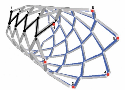
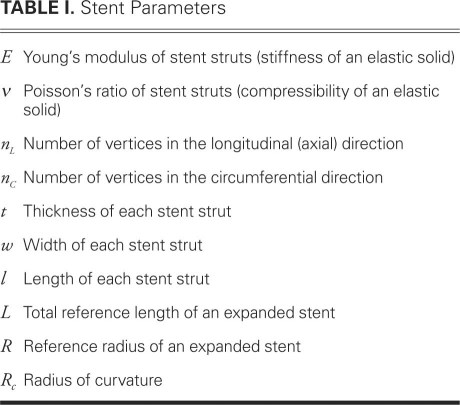
A stent is a 3D body that can be defined as a union of 3D struts made of a metallic alloy (Fig 1). The mechanical properties of stents are usually described in terms of the theory of elastoplasticity, which characterizes deformation of materials as a function of the applied load.25,26 For large loads, a plastic deformation takes place, causing irreversible breakage of bonds and the formation of dislocations and slip planes.27 Such a deformation occurs, for example, when a stent is fully expanded from its undeformed, initial state by means of balloon inflation. For relatively small loads, however, a stent behaves as a linearly elastic body: after the load is removed, the stent assumes its original configuration. The response of a stent to small loads within the realms of linear elasticity is the type of behavior that interests us. In this case, the mechanical properties of an isotropic material are characterized by Young's modulus E, which represents the stiffness of an elastic solid (stent struts), and by Poisson's ratio ν, which represents the compressibility of an elastic solid (stent struts) (Appendix 1). The geometric properties of stents included in our study are listed in Table I.
Fig. 1 Three-dimensional computer reconstruction of a stent with 6 vertices in the circumferential direction and 9 vertices in the longitudinal direction.
TABLE I. Stent Parameters
Computational Model
We developed a new mathematical model in which the stent frame is represented by a mesh of 1D curved rods (struts).23 Furthermore, we developed a FEM for a computational simulation of the mathematical model. This new approach can be applied to stents with arbitrary geometries. The 1D approximation of stent struts as curved rods makes the FEM simulation incomparably simpler and faster than the standard approaches using black-box testing software, such as ANSYS® (ANSYS; Canonsburg, Pa), which approximate stent struts as 3D bodies. We developed a program in C++ computational language to implement our approach. We worked with frames consisting of 50 to 300 vertices. The time required for solving a problem numerically varied from 0.3 to 5 sec on a server with a 3.0-GHz processor and 2 GB of random access memory (RAM). In contrast, standard approaches using 3D approximations of stent struts take from several hours to a day to simulate 1 stent configuration. In addition, the number of nodes that it takes to approximate each 3D stent strut with sufficient accuracy often exceeds the computational capabilities (memory) of standard machines. We compared the 1D and 3D approaches28 and concluded that, for patient-specific calculations performed in real time, our algorithm is the one that should be used.
Testing Conditions
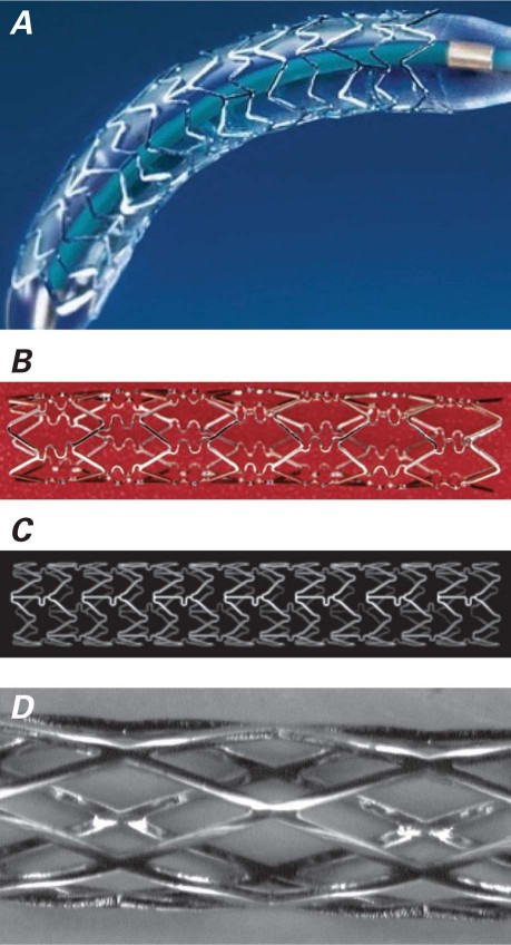
We computationally calculated the response of several different stent configurations and types of materials to the pressure load exerted on a stent in its expanded state. The stent models included a nonuniform Express-like stent (stent E), a Cypher-like stent (stent C), a Xience-like stent (stent X), and 3 additional computer-generated models (Fig. 2). All of the nonuniform stent models were compared against a uniform Palmaz-like stent (stent P). We considered 2 types of loading: 1) radial loading causing compression and 2) loading causing bending.
Fig. 2 Stents used as the bases for computational models.
A) Express® stent (Boston Scientific Corporation; Natick, Mass); B) Cypher® stent (Cordis Corporation, a Johnson & Johnson company; Miami Lakes, Fla); C) Xience® stent (Abbott Vascular, part of Abbott Laboratories; Abbott Park, Ill); D) Palmaz stent (Cordis Corporation).
Uniform Compression. We subjected the stents to a uniformly distributed force in the radial direction, causing compression. The compression force corresponded to a pressure load of 0.5 atm. We calculated the corresponding force by considering the 0.5-atm pressure load of a cylinder (for example, a blood vessel) of length L acting on a stent of the same length L. This pressure load is physiologically reasonable (Appendix 2).
Bending. We subjected the stents to forces that cause bending. These forces were applied pointwise to the center of a given stent and to the end points. The force at the end points was applied in the opposite direction from the force at the center of the stent. For each stent, the magnitude of the total applied force was calculated to be equal to the force that a curved vessel, with a radius of curvature R c = 2.5 cm, exerts on a straight stent inserted into a curved vessel.
A measure of curvature of a bent stent was calculated as a reciprocal of the radius of curvature for a middle curve of each stent (a small radius of curvature means a large curvature).
Interpreting the Models
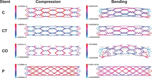
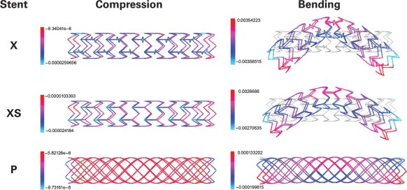
In the relevant figures, blue/cyan denotes maximal displacement, and red denotes minimal displacement. The numbers in the scale bars indicate the magnitude of the displacement, and the values are in meters. The usual exponential notation is used where necessary (for example, e–6 denotes 10−6).
Results
Express-Like Stent
Stent E, the Express-like stent model, had alternating zigzag rings. The number of vertices was n C 1 = 6 and n 2 C = 8 in the circumferential direction and n L = 30 in the longitudinal direction (Fig. 2A). The expanded stent radius was R = 1.5 mm (3.0-mm diameter), and the expanded length was L = 17 mm. The computationally calculated mechanical responses were compared to those of stent P, a uniform Palmaz-like stent with equivalent geometric characteristics (Fig. 2D).
Figure 3 shows the effects of uniform compression and bending on these models. The following conclusions were reached:
Fig. 3 Comparison of radial displacement under uniform compression and bending forces in stent E and stent P (the uniform control model).
Blue/cyan = maximal displacement;
red = minimal displacement
Motion images are available at www.texasheart.org/journal.
Under compression, stent E was less rigid than stent P.
Under compression, stent E was stiffest at the zigzag rings consisting of short stent struts.
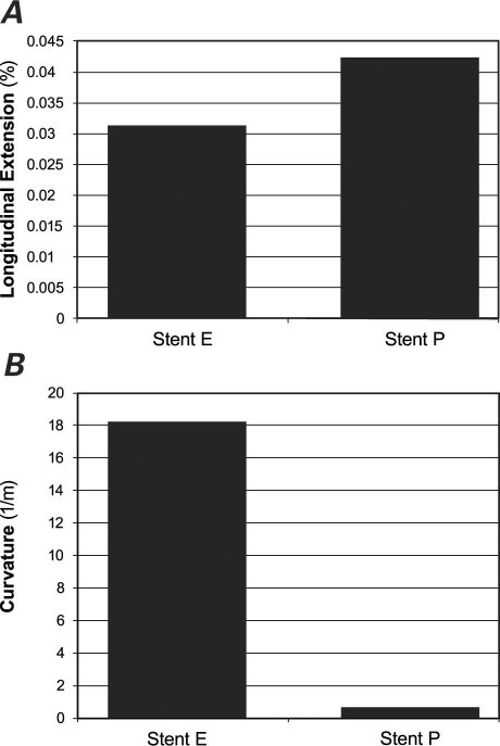
Under compression, the longitudinal extension of stent E was smaller than that of stent P (Fig. 4A).
When exposed to bending forces, stent E was more flexible than stent P (Fig. 4B).
Fig. 4 Comparison of A) longitudinal extension under uniform compression and B) curvature under bending forces in stent E and stent P (the uniform control model).
Cypher-Like Stents
We performed computational studies of the mechanical properties in 3 types of nonuniform Cypher-like stents.
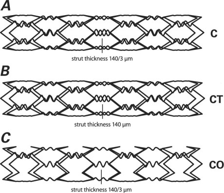
Stent C. This model had a closed-cell design, like that of a Cypher stent. Figure 5A shows the geometry of the stent generated by our computer algorithm. The stent struts were made of 316L stainless steel (t = 140 μm) and were organized in alternating, reflected rings. The rings were connected by sinusoidally shaped struts (t = 140/3 μm). The number of vertices was n C = 6 in the circumferential direction and n L = 16 in the longitudinal direction. The expanded radius was R = 1.5 mm (3.0-mm diameter).
Fig. 5 Nonuniform geometric design and strut thickness of the Cypher-like stent models: A) stent C with thin struts, B) stent CT with thick sinusoidal struts, and C) stent CO with open-cell design.
Stent with Thick Sinusoidal Struts. We studied a computer-modified stent that had the same geometry as stent C, except that the sinusoidally shaped stent struts were thicker (t = 140 μm) (Fig. 5B). We called this model stent CT.
Stent with Open-Cell Design. We studied another computer-modified stent that had the same geometry as stent C, except that the sinusoidally shaped stent struts connected only every other vertex in the circumferential direction (Fig. 5C). We called this model stent CO.
Uniform Stent. The computationally calculated mechanical responses of the 3 Cypher-like stents were compared with those of stent P, a uniform Palmaz-like stent that had equivalent geometric characteristics: n C = 6, n L = 16, and expanded radius R = 1.5 mm (3.0-mm diameter).
Figure 6 shows the effects of uniform compression and bending on these models. Several conclusions can be drawn:
Fig. 6 Comparison of radial displacement under uniform compression and bending forces in the Cypher-like stent models: stent C with thin struts, stent CT with thick sinusoidal struts, and stent CO with open-cell design. Stent P was the uniform control model.
Blue/cyan = maximal displacement; red = minimal displacement
Motion images are available at www.texasheart.org/journal.
With respect to rigidity, the stents ranked in the following order: stent P (most rigid), stent CT, stent C, and stent CO (least rigid).
Stent C and stent CO had similar responses to compression: the lowest deformation occurred at the main (zigzag) struts, and the largest deformation occurred at the soft sinusoidal connecting struts.
Under compression, stent CT deformed more in the middle and less at the ends. The opposite was true for stent P.
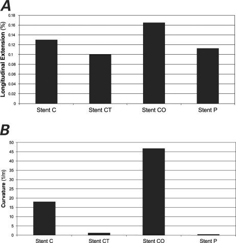
Stents C and stent CO, the stents with thinner connecting struts, had the largest longitudinal extension (Fig. 7A).
Stent CT, with its thick connecting struts, was minimally flexible under bending forces (Fig. 7B). The results were similar to those of stent P.
Stent CO, with its open-cell design and thin connecting struts, was by far the most flexible of the 4 stents considered, followed by stent C (Fig. 7B).
Fig. 7 Comparison of A) longitudinal extension under uniform compression and B) curvature under bending forces in the Cypher-like stent models: stent C with thin struts, stent CT with thick sinusoidal struts, and stent CO with open-cell design. Stent P was the uniform control model.
Xience-Like Stents
We performed computational studies of the mechanical properties of the following 2 types of nonuniform Xience-like stents.
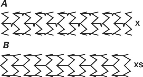
Stent X. The geometry of this stent was like that of the Multi-Link Mini Vision® device (Abbott Vascular, part of Abbott Laboratories; Abbott Park, Ill), which resembles the Xience® stent (Abbott Vascular) (Fig. 2C). Figure 8A shows the geometry of the Xience-like stent generated by our computer algorithm. The stent struts, made of L-605 cobalt–chromium alloy (Young's modulus E = 2.43×10¹¹ Pa), were 0.08 mm thick. The stent struts were organized in zigzag (in-phase) rings connected with horizontal struts, which contained a wiggle near the protruding vertex of a zigzag ring. Stent X had n C = 6 vertices in the circumferential direction and n L = 24 vertices in the longitudinal direction, with expanded radius R = 1.5 mm (3.0-mm diameter).
Fig. 8 Nonuniform geometric design of the Xience-like stent models: A) stent X with zigzag (in-phase) rings connected with horizontal struts and B) stent XS with straight connecting struts.
Xience-Like Stent with Straight Connecting Struts. We studied a computer-modified stent that had the same geometry as stent X, except that the connecting horizontal struts were straight (Fig. 8B). We called this model stent XS.
Uniform Stent. The performance characteristics of the 2 Xience-like stents were compared with those of stent P, a uniform Palmaz-like stent that we assumed to be made of the L-605 cobalt–chromium alloy and to have n C = 6 vertices in the circumferential direction, n C = 24 vertices in the longitudinal direction, and expanded radius R = 1.5 mm (3.0-mm diameter).
Figure 9 shows the effects of uniform compression and bending on these models. On the basis of our computer simulations, we drew the following conclusions:
Fig. 9 Comparison of radial displacement under uniform compression and bending forces in the Xience-like stent models: stent X with zigzag (in-phase) rings connected with horizontal struts and stent XS with straight connecting struts. Stent P was the uniform control model.
Blue/cyan = maximal displacement; red = minimal displacement
Motion images are available at www.texasheart.org/journal.
Under compression, both stent X and stent XS were slightly less rigid in the middle and more rigid at the ends. In contrast, uniform stent P was more rigid in the middle and less rigid at the ends.
Stent X underwent the largest radial deformation at the connecting struts, and the smallest radial displacement at the end struts.
Stent XS underwent the largest radial displacement at the points where the connecting struts met the main zigzag struts at the interior angle, and the smallest radial displacement at the end struts.
The radial deformation in stent X and stent XS was of the same order of magnitude for both devices.
The radial stiffness of uniform stent P was larger than that of stent X and stent XS.
Figure 10A shows that longitudinal elongation under uniform compression was smaller for stent X and stent XS than it was for stent P. The smaller longitudinal extension can be attributed to the in-phase zigzag rings without opposing vertices (in contrast to the Cypher-like stents, which have opposing vertices).
When exposed to bending forces, stent X and stent XS were considerably less rigid than stent P (Fig. 10B).
Fig. 10 Comparison of A) longitudinal extension under uniform compression and B) curvature under bending forces in the Xience-like stent models: stent X with zigzag (in-phase) rings connected with horizontal struts and stent XS with straight connecting struts. Stent P was the uniform control model.
Discussion
Mathematical and computer modeling of endovascular stents is an efficient way to improve the design and performance of these devices. Using a novel, simple, and efficient FEM algorithm, we studied and compared the mechanical properties of several stents in their fully expanded state. These included a Palmaz-like stent, Express-like stent, Cypher-like stent, and Xience-like stent. In addition to studying the brand-name stents, we investigated several new computer-generated stents, such as a computer-modified Cypher-like stent with thick sinusoidal struts, a computer-modified Cypher-like stent with an open-cell design, and a computer-modified Xience-like stent with straight connecting struts. Other geometric and mechanical parameters included the length, thickness, width, and shape of the stent struts; geometric distribution of the stent struts; the Young modulus and Poisson ratio of the strut material; and expanded reference diameter. Expanded stents were exposed to physiologically reasonable pressure loads that resulted in compression and bending.
Our findings have several implications:
Stents that do not fully expand are less rigid and, therefore, exhibit larger deformation. Mathematical confirmation of the importance of fully deploying and apposing stents to arterial walls implies that postdilation is a highly advisable practice.
Nonuniform pressure loads cause higher stent deformation (as, for example, when a stent is inserted into a vessel lumen with either high-diameter gradients or a non-axially-symmetric geometry, which may be due to plaque deposits that have not been uniformly pushed against the wall of a diseased artery during balloon angioplasty). (See Tambaca and colleagues23 for a detailed mathematical/computational study.) In such geometries, stents deform more under radial loading. This is a mathematical indication of the importance of predilation of the lesion to facilitate full stent expansion.
Uniform geometry (such as that in our stent P model) gives rise to the most rigid stents, making them less likely to yield under radial force and bending.
The open-cell design (such as that in stent E, stent CO, stent X, and stent XS) is generally associated with higher flexibility during bending. This observation is exceptionally valuable, because the longitudinal straightening effect of a rigid stent has been clinically associated with an increased incidence of major adverse cardiovascular events.29
Stents with sinusoidal connecting struts (such as Cypher-like stents) deform to the greatest extent under a uniform radial force (see the high magnitude of radial deformation shown in Fig. 6).
Stents with in-phase circumferential rings (such as the Xience-like stents) exhibit smaller longitudinal extension during radial forcing than do stents with alternating, reflected rings (such as Palmaz-like and Cypher-like stents). This information could be clinically important when landing a stent in an angle formed by a native artery.
Radial stiffness, bending flexibility, and the smallest change in stent length during radial forcing are exhibited by stents that have in-phase circumferential rings that are connected with straight horizontal struts in an open-cell design, such as that in stent XS (Figs. 8B and 9).
Further testing and computational studies involving fluid-structure interaction analysis and material-fatigue analysis need to be performed to clarify the mechanical behavior of stents in reference to radial stiffness, bending resistance, number and formation of hinge points, stent conformation to arterial morphology, biologic changes of a bending segment in terms of restenosis, and material fatigue that may result in stent fracture. Figure 11 shows an example of early in-stent restenosis that might have been associated with high compression and bending forces in the stented region due to the curved morphology of the right coronary artery. Placing a flexible stent that conformed to the artery, instead of a rigid stent, might have proved more effective.
Fig. 11 Example of stenosis in which placement of a flexible stent that conformed to the curved arterial morphology might have proved more suitable. Angiograms show A) blockage at a bending point in the right coronary artery, B) a rigid stent placed at the stenosed location, and C) in-stent stenosis at 3 months.
The computer model that we developed can be expanded to explore the effects of stent design on arterial wall mechanics,29–33 to evaluate radial force,34,35 and to study material fatigue under different loads. In addition, this study shows the feasibility of using our algorithm in a clinical setting. Standard computational approaches have used 3D approximations of stent struts; however, the number of nodes required to approximate each 3D strut with sufficient accuracy often exceeds the computational capabilities (memory) of standard computers. One stent configuration can take several hours to a day. Our simple 1D model can provide patient-specific calculations in real time.
Acknowledgment
The authors thank Virginia Fairchild, of the Department of Scientific Publications, Texas Heart Institute at St. Luke's Episcopal Hospital, for editorial help in the preparation of this manuscript.
Supplementary Material
Appendix 1
Background in Elasticity Theory
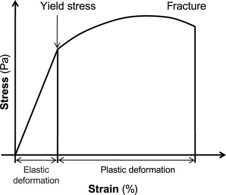
The response of a material to an applied load is usually represented by a stress-strain relationship (Fig. 1). Stress σ is a measure of the average amount of force F exerted per unit area A: σ = F/A. Strain ɛ is the geometric measure of deformation representing the relative displacement between particles in the material body. For example, extensional strain ɛ of a material line element or fiber that is axially loaded is expressed as the change in length ΔL per unit of the original, reference length L of the line element or fibers: ɛ = ΔL/L.
Fig. 1 Stress-strain relationship.
The stress (load) beyond which a material will undergo a plastic deformation is called the yield stress (Fig. 1). Different materials and different stent configurations have different yield stresses.
The relationship between stress σ and strain ɛ can be represented by a nonlinear function F: σ = F(ɛ).
Assuming that strain is small, one can use the Taylor series formula to express σ as a function of ɛ in the following way:
Here F′(0) denotes the derivative of F with respect to ɛ evaluated at ɛ = 0. For small ɛ, higher powers of ɛ are even smaller, so one may neglect the contribution of the terms with ɛ2 and higher. As a result, σ can be approximated with the following relationship:
Assuming that zero stress causes zero strain, that is, F(0)=0, one obtains σ = F′(0)ɛ.
To simplify the notation in this manuscript, we use A to denote F′(0). As stated below, A is a matrix with coefficients that describe material properties such as the Young modulus and the Poisson ratio.
The following basic formulas characterize the mechanics of isotropic, linearly elastic materials. As before, u denotes the displacement vector in the 3-dimensional space
 |
Deformation is measured by strain ɛ. For small deformations,
which is known as the infinitesimal strain tensor. Here ∇u denotes the gradient of u, which is the matrix of partial derivatives of u denoting the change (derivative) of each of the 3 coordinates of u in each of the 3 independent spatial directions. Thus, such a matrix has to have 9 entries. Indeed, the gradient of u is defined to be
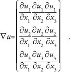 |
The transpose of ∇u, denoted by (∇u) T , is the matrix that is obtained from ∇u by switching its rows and columns to obtain
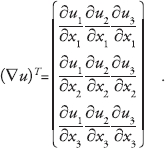 |
Thus, infinitesimal strain ɛ(u) can be written in components as a matrix of the following form:
 |
For i, j = 1, 2, 3, we denote by ε ij the entries of the strain matrix (1). Then,
Keeping this notation in mind, one is in a position to write the constitutive law for an isotropic, linearly elastic solid. The constitutive law describes how a solid deforms after an application of a force. Because strain measures the deformation and stress corresponds to the force, the constitutive law is given in terms of the stress-strain relationship. For an isotropic, linearly elastic solid, the stress-strain relationship is given by σ = Aɛ, which can be written in components as:
 |
Matrix A contains the parameters that define the behavior of the underlying material. For an isotropic, linearly elastic solid, only 2 parameters are necessary for a complete description of the solid behavior: the Young modulus of elasticity E and the Poisson ratio ν.
The Young modulus of elasticity E is the slope of the stress-strain curve in uniaxial tension. It has dimensions of stress (N/m2 = Pa) and is usually large for steel, E = 210 × 109 Pa. One can think of E as the measure of the stiffness of a solid. The larger the value of E, the stiffer the solid.
Poisson's ratio ν is the ratio of lateral to longitudinal strain in uniaxial tensile stress. It is dimensionless, typically ranges from 0.2 to 0.49, and is around 0.3 for most metals. One can think of ν as the measure of the compressibility of the solid. If ν = 0.5, the solid is incompressible; its volume remains constant no matter how it is deformed.
Appendix 2
Calculation of the Force by Which an Expanded Artery Acts on a Stent
A uniformly distributed force in the radial direction was applied to stents, causing compression. Radial displacement from the expanded configuration was measured. The compression force corresponded to the pressure load of 0.5 atm. This pressure load is physiologically reasonable. We used the Law of Laplace to estimate the exterior pressure loads applied to an inserted stent. This law, which relates the displacement u of the arterial wall with the transmural pressure p−p 0, reads1,2:
where E is the Young modulus of the vessel wall, h the vessel wall thickness, R the vessel (reference) radius, and ν the Poisson ratio. For incompressible materials such as arterial walls, ν = ½. The Young modulus of a coronary artery is between 105 Pa and 106 Pa (see Canic and co-authors1 and the references therein). For our calculation, we took the intermediate value of E = 5×10⁵ Pa and the reference coronary artery radius R = 1.3 mm with the vessel wall thickness h = 1 mm. To provide reasonable fixation, stents are typically oversized by 10% of the native vessel radius. Thus, 10% displacement of a coronary artery of radius 1.3 mm gives a displacement u = 0.13 mm. By plugging these values into formula (1), one gets p−p 0 ≈ 5×10⁴ Pa, which equals 0.5 atm. Thus, a pressure load of 0.5 atm is necessary to expand a coronary artery by 10% of its reference radius. Now, the total force by which an artery acts on a stent of length L and radius R is equal in magnitude, but of opposite sign, to the total force that is necessary to expand a section of a vessel of length L and radius R by 10%. Because pressure equals force per unit area, the corresponding total force F that is needed to expand a section of an artery of length L and radius R by 10% is
where 2RπL is the luminal area of the arterial section of length L and radius R. We have used this expression in this article to calculate the total force by which an expanded artery acts on a stent with given geometric characteristics.
References
- 1.Canic S, Hartley CJ, Rosenstrauch D, Tambaca J, Guidoboni G, Mikelic A. Blood flow in compliant arteries: an effective viscoelastic reduced model, numerics, and experimental validation. Ann Biomed Eng 2006;34(4):575–92. [DOI] [PubMed]
- 2.Fung YC. Biomechanics: circulation. 2nd ed. New York: Springer-Verlag; 1997.
Footnotes
Address for reprints: David Paniagua, MD, Michael E. DeBakey VA Medical Center, 2002 Holcombe Blvd., Houston, TX 77030
E-mail: davidpaniag@pol.net
This study was supported by the Croatian Ministry of Science, Education, & Sports (MZOS) (grant 037-0693014-2765); National Science Foundation (grant DMS-0806941); National Science Foundation/National Institutes of Health (grant DMS-0443826); Texas Higher Education Board (Advanced Research Program grant 003652-0051-2006); and University of Houston (Grants to Enhance & Advance Research [GEAR], 2007).
References
- 1.Garasic JM, Edelman ER, Squire JC, Seifert P, Williams MS, Rogers C. Stent and artery geometry determine intimal thickening independent of arterial injury. Circulation 2000;101(7):812–8. [DOI] [PubMed]
- 2.Kastrati A, Mehilli J, Dirschinger J, Dotzer F, Schuhlen H, Neumann FJ, et al. Intracoronary stenting and angiographic results: strut thickness effect on restenosis outcome (ISAR-STEREO) trial. Circulation 2001;103(23):2816–21. [DOI] [PubMed]
- 3.Lau KW, Johan A, Sigwart U, Hung JS. A stent is not just a stent: stent construction and design do matter in its clinical performance. Singapore Med J 2004;45(7):305–12. [PubMed]
- 4.McLean DR, Eiger NL. Stent design: implications for restenosis. Rev Cardiovasc Med 2002;3 Suppl 5:S16–22. [PubMed]
- 5.Morton AC, Crossman D, Gunn J. The influence of physical stent parameters upon restenosis. Pathol Biol (Paris) 2004;52 (4):196–205. [DOI] [PubMed]
- 6.Hausdorf G. Mechanical and biophysical aspects of stents. In: Rao PS, Kern MJ, editors. Catheter based devices for the treatment of non-coronary cardiovascular disease in adults and children. Philadelphia: Lippincott Williams & Wilkins; 2003. p. 271–85.
- 7.Kastrati A, Schomig A, Dirschinger J, Mehilli J, von Welser N, Pache J, et al. Increased risk of restenosis after placement of gold-coated stents: results of a randomized trial comparing gold-coated with uncoated steel stents in patients with coronary artery disease. Circulation 2000;101(21):2478–83. [DOI] [PubMed]
- 8.Rogers C, Tseng DY, Squire JC, Edelman ER. Balloon-artery interactions during stent placement: a finite element analysis approach to pressure, compliance, and stent design as contributors to vascular injury. Circ Res 1999;84(4):378–83. [DOI] [PubMed]
- 9.Dyet JF, Watts WG, Ettles DF, Nicholson AA. Mechanical properties of metallic stents: how do these properties influence the choice of stent for specific lesions? Cardiovasc Intervent Radiol 2000;23(1):47–54. [DOI] [PubMed]
- 10.Andersen HR, Maeng M, Thorwest M, Falk E. Remodeling rather than neointimal formation explains luminal narrowing after deep vessel wall injury: insights from a porcine coronary (re)stenosis model. Circulation 1996;93(9):1716–24. [DOI] [PubMed]
- 11.Gruntzig AR, Meyler RK, Hanna ES, Turina MI. Transluminal angioplasty of coronary artery stenosis [abstract]. Circulation 1977;56(suppl III):III–84.
- 12.Ormiston JA, Dixon SR, Webster MW, Ruygrok PN, Stewart JT, Minchington I, West T. Stent longitudinal flexibility: a comparison of 13 stent designs before and after balloon expansion. Catheter Cardiovasc Interv 2000;50(1):120–4. [DOI] [PubMed]
- 13.Post MJ, Borst C, Kuntz RE. The relative importance of arterial remodeling compared with intimal hyperplasia in lumen renarrowing after balloon angioplasty. A study in the normal rabbit and the hypercholesterolemic Yucatan micropig. Circulation 1994;89(6):2816–21. [DOI] [PubMed]
- 14.Schmidt W, Behrens P, Behrend D, Schmidt KP. Measurement of mechanical properties of coronary stents according to the European Standard prEN 12006–3. Prog Biomed Res 1999;4(1):45–51.
- 15.Sigwart U, Puel J, Mirkovitch V, Joffre F, Kappenberger L. Intravascular stents to prevent occlusion and restenosis after transluminal angioplasty. N Engl J Med 1987;316(12):701–6. [DOI] [PubMed]
- 16.Squire JC, Rogers C, Edelman ER. Measuring arterial strain induced by endovascular stents. Med Biol Eng Comput 1999; 37(6):692–8. [DOI] [PubMed]
- 17.Dumoulin C, Cochelin B. Mechanical behaviour modelling of balloon-expandable stents. J Biomech 2000;33(11):1461–70. [DOI] [PubMed]
- 18.Gasser TC, Holzapfel GA. A rate-independent elastoplastic constitutive model for biological fiber-reinforced composites at finite strains: continuum basis, algorithmic formulation and finite element implementation. Comput Mech 2002;29 (4–5):340–60.
- 19.Holzapfel GA, Stadler M, Gasser TC. Towards a computational methodology for optimizing angioplasty treatments with stenting. In: Holzapfel GA, Ogden RW, editors. Mechanics of biological tissue. Heidelberg: Springer-Verlag; 2005. p. 225–40.
- 20.Holzapfel GA, Stadler M, Gasser TC. Changes in the mechanical environment of stenotic arteries during interaction with stents: computational assessment of parametric stent designs. J Biomech Eng 2005;127(1):166–80. [DOI] [PubMed]
- 21.Migliavacca F, Petrini L, Colombo M, Auricchio F, Pietrabissa R. Mechanical behavior of coronary stents investigated through the finite element method. J Biomech 2002;35(6):803–11. [DOI] [PubMed]
- 22.Migliavacca F, Petrini L, Montanari V, Quagliana I, Auricchio F, Dubini G. A predictive study of the mechanical behaviour of coronary stents by computer modelling. Med Eng Phys 2005;27(1):13–8. [DOI] [PubMed]
- 23.Tambaca J, Kosor M, Canic S, Paniagua D. Mathematical modeling of vascular stents. SIAM J Appl Math 2010;70(6):1922–52.
- 24.Jurak M, Tambaca J. Derivation and justification of a curved rod model. Math Model Meth Appl Sci 1999;9(7):991–1014.
- 25.Bower AF. Applied mechanics of solids. Boca Raton (FL): CRC Press; 2009.
- 26.Lubarda VA. Elastoplasticity theory. Boca Raton (FL): CRC Press; 2002.
- 27.Mehta A. X-ray diffraction and the fight against heart disease [monograph on the Internet]. SLAC Today 2006 Nov 2 [cited 2011 Jul 22]. Available from: http://today.slac.stanford.edu/feature/ROW-110206.asp.
- 28.Canic S, Tambaca J. Cardiovascular stents as PDE nets: 1D vs. 3D. IMA J Appl Math. In press.
- 29.Gyongyosi M, Yang P, Khorsand A, Glogar D. Longitudinal straightening effect of stents is an additional predictor for major adverse cardiac events. Austrian Wiktor Stent Study Group and European Paragon Stent Investigators. J Am Coll Cardiol 2000;35(6):1580–9. [DOI] [PubMed]
- 30.Canic S, Hartley CJ, Rosenstrauch D, Tambaca J, Guidoboni G, Mikelic A. Blood flow in compliant arteries: an effective viscoelastic reduced model, numerics, and experimental validation. Ann Biomed Eng 2006;34(4):575–92. [DOI] [PubMed]
- 31.Hao C, Morse D, Morra F, Zhao X, Yang P, Nunn B. Direct aqueous determination of glyphosate and related compounds by liquid chromatography/tandem mass spectrometry using reversed-phase and weak anion-exchange mixed-mode column. J Chromatogr A 2011;1218(33):5638–43. [DOI] [PubMed]
- 32.Fung YC. Biomechanics: circulation. 2nd ed. New York: Springer-Verlag; 1997.
- 33.Fung YC. Biomechanics: mechanical properties of living tissues. 2nd ed. New York: Springer-Verlag; 1993.
- 34.Bedoya J, Meyer CA, Timmins LH, Moreno MR, Moore JE. Effects of stent design parameters on normal artery wall mechanics. J Biomech Eng 2006;128(5):757–65. [DOI] [PubMed]
- 35.Rieu R, Barragan P, Masson C, Fuseri J, Garitey V, Silvestri M, et al. Radial force of coronary stents: a comparative analysis. Catheter Cardiovasc Interv 1999;46(3):380–91. [DOI] [PubMed]
Associated Data
This section collects any data citations, data availability statements, or supplementary materials included in this article.


