Abstract
An ophthalmic adaptive optics (AO) imaging system is especially affected by pupil edge effects due to the higher noise and aberration level at the edge of the human pupil as well as the impact of head and eye motions on the pupil. In this paper, a two-step approach was proposed and implemented for reducing the edge effects and improving wavefront slope boundary condition. First, given an imaging pupil, a smaller size of sampling aperture can be adopted to avoid the noisy boundary slope data. To do this, we calibrated a set of influence matrices for different aperture sizes to accommodate pupil variations within the population. In step two, the slope data was extrapolated from the less noisy slope data inside the pupil towards the outside such that we had reasonable slope data over a larger aperture to stabilize the impact of eye pupil dynamics. This technique is applicable to any Neumann boundary-based active /adaptive modality but it is especially useful in the eye for improving AO retinal image quality where the boundary positions fluctuate.
OCIS codes: (010.1080) Active or adaptive optics, (220.1080) Active or adaptive optics, (170.1790) Confocal microscopy, (330.4460) Ophthalmic optics and devices
1. Introduction
For over ten years adaptive optics (AO) has been implemented in ophthalmic imaging for wavefront aberration correction [1]. In general, in order to gain high resolution retinal images a high accuracy AO wavefront correction is required. One of the issues that arises in AO for the eye is that the pupil of the eye varies a bit in space and size, because of head movements and eye rotation, both over time in a single individual or between individuals. There are two possible approaches to handling this. The first would be to build an AO system with a fixed system pupil that was adequate for most individuals being tested. The second would be to build a system that has a large pupil, and then adapt the control system so that it achieves an optimum wavefront control for each individual based on their own pupil. This paper addresses this second approach for systems with the Shack-Hartmann (SH) slope sensor as the wavefront sensor.
Working from wavefront slope data (i.e. wavefront derivatives) [2], the problem of AO control is how to estimate the wavefront phase that can best represent the slope measurements and how to control the deformable mirror (DM) figure to correct wavefront phase. As show in Eq. (1), a slope- or Laplacian curvature-based wavefront estimation is a Neumann boundary problem of Poisson’s equation [3],
| (1) |
where W is the wavefront under estimation over the pupil , and is the wavefront boundary derivative that is normal to the boundary curves(“n” denotes the normal to the pupil boundary). The function can be either the direct wavefront local curvature measurements or the estimates of wavefront local curvature from wavefront gradient measurements.
The wavefront shape is a combination of contributions from wavefront Laplacians at each point and slopes at the boundary [4,5]. However the low order wavefront figure shape is determined predominantly by slopes at the pupil boundary. Given a Green function in a polar system, the wavefront solution can be written as [6–8]
| (2) |
where the first term on the right side is the contribution from the wavefront local curvature and the second term is from Neumann boundary slope (i.e. derivatives). Therefore, for wavefronts with the low order Zernike polynomials, such as orientation (tip/tilt), defocus and astigmatism, the wavefront curvature is either zero or a constant, so is the first term on the right side of Eq. (2). Therefore the estimated wavefront shape is dominated by the second term, which is an integration of the Neumann boundary slopes [9]. As a result poor boundary conditions (i.e. noisy slope data at wavefront edges) can introduce large deviations in wavefront estimation [10]. Unfortunately, due to optical artifacts such as the pupil edge obscuration and vignetting, the measurements of wavefront exiting from the human pupil usually have large errors at the boundaries [11]. In addition, the human pupils tend to change during an imaging session. For high resolution AO control, whether the DM commands are based on slope data or based on wavefront phase estimate from slope measurements, it is critical to reduce the errors arising from the edge effects. Thus, how to handle the boundary condition in wavefront sensing is critical in further improving high accuracy wavefront correction in living human subjects. In this paper, we focus on the boundary problem of AO control addressed from slope data directly to the actuator commands.
2. Methods
The dual deformable mirror (DM) adaptive optics system, configured as a woofer-tweeter (W-T) system, has been previously described [12–18]. In the AOSLO system, the wavefront sensor is the SH sensor. Two DMs were employed for wavefront aberration corrections: One DM is a “woofer” corrector for the low order, large amplitude wavefront errors, and another DM is a “tweeter” corrector for the high order, small amplitude wavefront errors. Figure 1 illustrates the Indiana wide-field dual DM AOSLO system we developed [18], where the woofer is the 52-actuator Mirao DM from Imagine Eyes, and the tweeter is the 140-actuator MEMS DM from Boston Micromachines Corporation (BMC). The eye pupil, the fast and slow scanners, the woofer and tweeter DMs, and the lenslet array are optically conjugated [17,18]. In this paper, we add boundary control to the Indiana dual DM AOSLO.
Fig. 1.
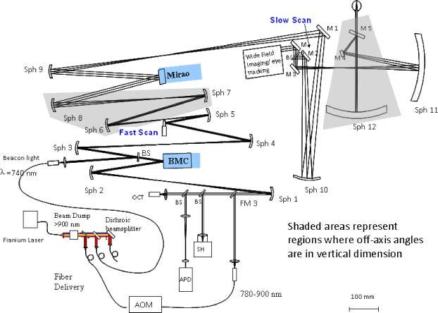
Indiana wide field dual DM AOSLO system.
Previous work addressed the wavefront boundary condition in AO retinal imaging by shrinking the system pupil, typically smaller than the human eye pupil [19]. However, shrinking the system pupil decreases the theoretical Rayleigh resolution capability of the system and does not take advantage of the large pupils that some subjects may have. In this section we present a two-step approach.
2.1. Step one: customizing influence matrices for different pupil sizes
To avoid the edge effect, we calibrate the influence matrix with the SH sampling size that is immediately smaller than a given physical pupil. To accommodate subjects with different pupil sizes, we calibrated a series of influence matrices with the ascending SH sampling grids from 12 × 12 to 22 × 22, for example, corresponding to sampling aperture sizes from Φ4.32mm to Φ8mm with the lenslet pitch size 0.36 mm (Table 1 ). This allows us to use a large influence matrix for a large pupil and a small influence matrix for a small pupil. With the full coverage of calibrated influence matrices, the boundary condition can be properly handled by adopting a properly sized influence matrix. An equivalent-yet-simpler-to-operate approach is to calibrate the influence matrix once with the maximum pupil size (for example, 22 × 22), and then the influence matrix that best matches the subject pupil size can be obtained by customizing the influence functions on the fly.
Table 1. SH sampling grid series and their corresponding pupil sizes.
| SH Grid | 12×12 | 13×13 | 14×14 | 15×15 | 16×16 | 17×17 | 18×18 | 19×19 | 20×20 | 21×21 | 22×22 |
|---|---|---|---|---|---|---|---|---|---|---|---|
| Pupil Size Φ (mm) | 4.32 | 4.68 | 5.04 | 5.4 | 5.78 | 6.12 | 6.48 | 6.84 | 7.22 | 7.56 | 8 |
2.2. Step two: slope extrapolation across pupil boundary
As shown in Section 3 (below) for a stationary pupil, AO imaging with the first approach provides improved performance compared to the use of the full pupil. However, in practice the pupils of human subjects are changing in position and in size throughout an imaging session, so it is necessary to either track the pupil and adapt the influence matrix size on the fly or come up with another approach. Current pupil tracking approaches are somewhat inconvenient and limited in accuracy, but it is typically done by manually adjusting subject position in real time. Another approach is to handle small changes in pupil location and edge dynamics by controlling a somewhat larger size of aperture relative to the human subject’s pupil, but rather than using the boundary values, we extrapolate the slope data across the original pupil boundary (yellow circle in Fig. 2 ) from the inside to the whole sampling aperture (red circle in Fig. 2). This was tested using a modal fitting of the wavefront data and applying it to the data outside of the measured aperture.
Fig. 2.
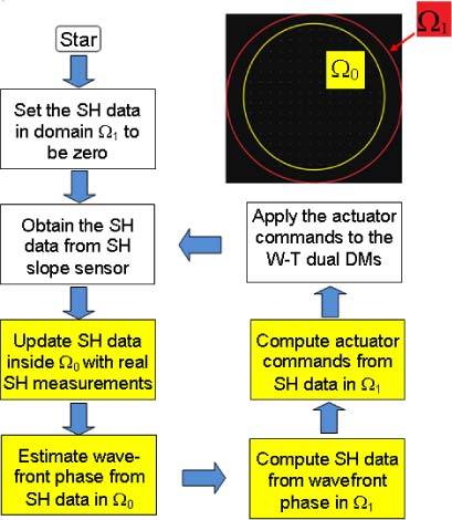
AO control with iterative boundary slope extrapolation. The four boxes in yellow are to show the AO inverse computation with boundary slope extrapolation.
As reported in previous papers, extrapolation of wavefront boundary can be achieved either with Gerchberg-type iterations or the extension method by copying the boundary slope [20–22]. Figure 2 is the flow chart we designed for the slope extrapolation algorithm. A Zernike modal fit (up to 35 terms) was performed over the slope data within Ω0. For the fitted wavefront, the wavefront slope data over a larger extended aperture Ω1 was computed, which acts to extend the wavefront slope data smoothly across the boundary Ω0. As such, the control system can use the measured slopes inside Ω0 and the extrapolated slopes between the pupil margin Ω0 and the larger aperture Ω1 (or using the slope data computed in the entire Ω1) for wavefront correction. Thus, the presence of slope estimates outside the pupil could help to stabilize the control as the subject pupil moves and changes its shape and size within the larger extended aperture Ω1. While the wavefront extrapolation does not perform as well as a “perfect” control might do, since it is not using the light coming from the pupil boundaries, it should provide a stable solution that is easy to compute in real-time, and thus improve the practical resolution of the AO imaging. That is, we improve the wavefront boundary condition by maintaining a larger sampling aperture yet avoiding the boundary slope noise arising from the partially filled SH lenslets. As a consequence, both the stability and accuracy of the AO wavefront control should be improved.
3. Results
3.1. Retinal AO imaging with customized influence matrix
3.1.A. Results with artificial eye
We used our AOSLO system with an artificial eye to compare AO imaging under different boundary conditions. The artificial eye was composed of a single lens with 100-mm focal length and a target (a dollar bill) on a movable slide. The physical pupil of the system was set to 5.78 mm in diameter, which was conjugated to the position of the lenslet array inscribed in a 16 × 16 SH grid (or SH 16 × 16). We first tested the AO imaging with a Φ7.22 mm sampling aperture (SH 20 × 20), and then with a Φ5.04 mm sampling aperture (SH 14 × 14), and the influence matrices for SH 20 × 20 and SH 14 × 14 were adopted accordingly. For the larger aperture, erroneous boundary slope data was included in AO control, while for the smaller aperture it was excluded. The dollar bill images are shown in Figs. 3 (a)-(b) for comparison, and the corresponding rms values are shown in Fig. 3(c). The averaged wavefront rms errors for the Φ7.22 mm and the Φ5.04 mm sampling apertures were 2.46 µm and 0.018 µm, respectively. To further test the concept, we set up another experiment to systematically vary the sampling aperture size from Φ4.32 mm (SH 12 × 12) to Φ8 mm (SH 22 × 22) as shown in Fig. 4 , where the physical pupil of the artificial eye was maintained at Φ7.22mm (SH 20 × 20). For this experiment, we conclude that when the sampling aperture was smaller than the physical pupil, the wavefront rms was about 0.025 µm; however, when the sampling aperture was larger (for example, SH 22 × 22), the wavefront rms value increased up to 0.3 µm.
Fig. 3.
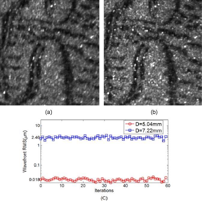
Model eye images obtained when the eye pupil was Φ5.68mm (SH 16 × 16) and the sampling aperture was set to (a) 20 × 20 SH sampling grid (Φ7.2mm) and (b) 14 × 14 SH sampling grid (Φ5.0mm). (c) is their wavefront rms comparison. The image resolution is improved by shrinking the pupil to avoid the slope errors at the wavefront boundary. Wavefront control accuracies with/without pupil adjustment differ by more than two log units.
Fig. 4.
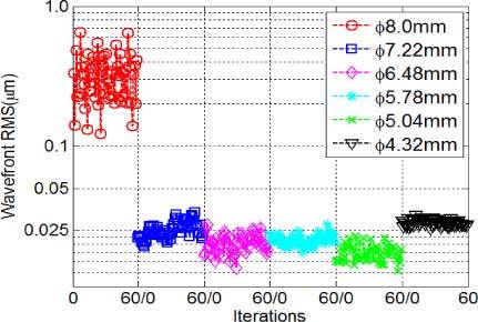
RMS comparisons for a model eye with a physical pupil size of Φ7.22mm. The sampling apertures were varying from Φ4.32mm to Φ8.0mm. RMS error increases only when the sampling aperture size was larger than the physical pupil size.
Although generally a smaller residual wavefront error implies better AO performance, in some situations when the wavefront errors are localized, wavefront rms would become inaccurate in characterizing image quality. For this reason we employed both wavefront rms value and average image brightness as the metrics. The average image brightness quantifies the light power passing through the confocal pinhole and reaching the detector when the pinhole is not too large relative to the diffraction limited PSF size [18]. That is, more light passes through the pinhole as AO control performance improves and the PSF size decreases. In this study the confocal pinhole we used had a diameter of 100 µm, which was about twice the size of the airy disk for our maximum pupil size.
To optimize the sampling aperture size, we tested the dual DM AO system by systematically varying the sampling aperture size from Φ5.04 mm to Φ7.56 mm, where the physical pupil of the artificial eye was set to Φ6.84 mm (Fig. 5 ). When the sampling aperture was larger than physical pupil, the AO control was unstable and of low accuracy. By reducing the sampling aperture size, the wavefront control accuracy was improved presumably because the estimates derived from partially filled lenslets at the pupil margin were avoided. When the sampling aperture size was equal to (or slightly smaller than) the physical pupil size, wavefront rms value decreased from 0.3 µm to 0.025 µm and the image intensity increased by 50% (grayscales increased from 60 to 90). However, continuing to reduce the sampling aperture size did not further decrease the residual wavefront rms, because AO control accuracy depends on the wavefront sensor accuracy and actuator positioning accuracy. According to Fig. 5, the optimal sampling aperture size, Φ6.48 mm (SH 18 × 18), was the largest aperture size that was immediately smaller than the physical pupil size, at which the image intensity reaches its maximum value.
Fig. 5.
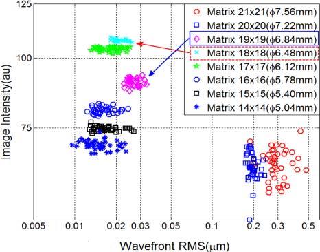
Optimizing the sampling aperture size for AO performance with an artificial eye. When the sampling aperture was smaller than the Φ6.84mm physical pupil (SH 19 × 19), the wavefront rms values were all very small (<0.03µm); however, among them the Φ6.48mm sampling aperture (SH 18 × 18) provided the brightest image.
3.1.B. Human imaging
To test the effect of pupil edge conditioning in vivo we performed retinal imaging on two healthy male subjects (S1 and S2). The subjects’ ages were 27 and 42, and they had refractive errors of 2.0 and 0 diopters. Both subjects were normal as determined by a complete eye examination, and their pupils were dilated with 0.5% tropicamide during data collection. Informed consent was obtained after a full explanation of the procedures and consequences of this study. The research was conducted according to the tenets of the Declaration of Helsinki, and all protocols were approved by the Indiana University Institutional Review Board.
Figure 6 shows the comparison of retinal images focused below the nerve fiber layer with and without incorporating a control for the boundary error. Figure 6(a) shows an image taken with the sampling aperture size set to Φ7.56mm (SH 21 × 21) when the physical pupil of subject S1 after dilation was Φ6.84mm (SH 19 × 19). That is, we were using a sampling aperture larger than the physical pupil of the eye, thereby the AO correction suffered from boundary slope errors. Figure 6(b) shows image obtained when the sampling aperture was set to the size of Φ5.4mm (SH 15 × 15) which was smaller than the physical aperture. To quantify the image quality, Michelson contrast (CM) and Fourier power spectra (Fig. 6(c)) of the two images were computed. While Michelson contrast was defined as the normalized difference between the highest and the lowest luminance of the image, the Fourier power spectrum provides a quantitative measure of the resolvable spatial frequency structures of the two images [18]. For example, we can use the power at 0.2 and 0.5 cycle/µm spatial frequencies to evaluate the image improvement. Since the 0.5 cycle/µm frequency was beyond the optical cutoff (Nyquist cutoff frequency was at 0.75cycle/µm), so the power at this frequency was basically image DC content (background brightness). While the DC content had an increase of 600 at 0.5 cycle/µm, the signal had a ~3 × 10³ power increase (from 1.3 × 10³ to 4.4 × 10³) at the 0.2 cycle/µm spatial frequency. Obviously the image with Φ5.4mm (SH 15 × 15) aperture in Fig. 6(b) not only has higher image intensity (average intensity changed from 43 to 103) and higher image contrast (CM changed from 0.83 to 0.90), but also has much more Fourier power for whole spectrum.
Fig. 6.
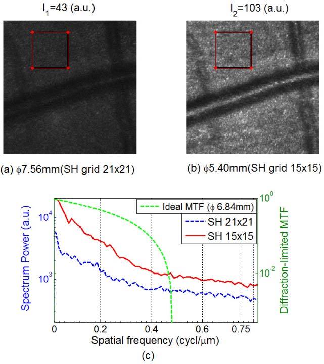
Retinal images focused just below the nerve fiber layer (450 × 450 pixels) of subject S1 with sampling apertures of (a) Φ7.56 mm and (b) Φ5.4 mm, where the dilated pupil of subject S1 was Φ6.84mm. (c) Spectrum power comparison based on the images within the two 120 × 120 pixels red-frame windows. We can clearly see the image improvement by avoiding the boundary errors.
This effect is systematic as shown in Fig. 7 . Here we varied the sampling aperture size in Fig. 7(a) from Φ4.32 mm (SH 12 × 12) to Φ4.68 mm (SH 13 × 13), Φ5.04 mm (SH 14 × 14), Φ5.4 mm (SH 15 × 15), Φ5.78 mm (SH 16 × 16), Φ6.12 mm (SH 17 × 17), Φ6.48 mm (SH 18 × 18), Φ6.84 mm (SH 19 × 19), and Φ7.22 mm (SH 20 × 20). As shown in Fig. 7(b), the brightest and best quality images were obtained when the sampling aperture was at Φ6.48 mm, which was the largest sampling aperture that was immediately smaller than the physical pupil of the subject.
Fig. 7.
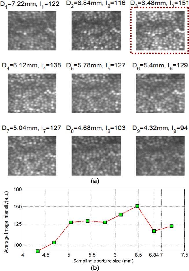
Optimizing the sampling aperture size for the AOSLO AO performance with subject S2. (a) Single frame retinal images with different sampling aperture sizes. (b) Plot of image intensity as a function of sampling aperture size. We can see that the optimal sampling aperture size was Φ6.48 mm, which was the maximum aperture immediately smaller than the Φ6.84 mm physical pupil.
3.2. Retinal AO imaging with slope extrapolation algorithm
3.2.A. Test of the slope extrapolation algorithm with artificial eye
In this Section we test the slope extrapolation algorithm on the artificial eye of Section 3.1. Figure 8 compares the image intensity (solid lines) and wavefront rms (dashed lines) as a function of the sampling aperture size with and without application of the slope extrapolation algorithm. The physical pupil size was Φ5.4mm (SH 15 × 15). When the sampling aperture size was smaller than the physical pupil size, the wavefront control accuracy (both wavefront rms and image intensity) was the same for both conditions. However, when the sampling aperture size was larger than the physical pupil size, the wavefront rms increased rapidly and image intensity dropped markedly for AO control without slope extrapolation. However, wavefront rms was still maintained around 0.03 µm and the image intensity did not drop significantly with increasing pupil size for the slope extrapolation condition, which implies that the extrapolation is able to stabilize the boundary region of the pupil. While we did not improve the image quality further, we avoided the rapid degradation in image quality measured without extrapolation.
Fig. 8.
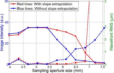
AO performance with/without boundary slope extrapolation measured on our AOLSO tested with the artificial eye. The physical pupil size was Φ5.4mm (SH 15 × 15). The solid lines represent image intensity curves, and the dash lines are wavefront rms values. The slope extrapolation method can improve the wavefront boundary condition and thereby improve AO performance.
3.2.B. Slope extrapolation with real subject
Figure 9 shows the effect of boundary extrapolation for subject S2. The dilated pupil size was about Φ6.5 mm (SH 18 × 18). We first set the sampling aperture to Φ6.12 mm (SH 17 × 17) without extrapolation and the highest image intensity was 70 gray scale units. Next, we increased the sampling aperture size to Φ7.22 mm (SH 20 × 20) and without extrapolation the image intensity dropped to about 26 gray scale units, and with extrapolation it remained at an average intensity of 77 gray scale units. To compare the stability over time, we calculated the standard deviations of mean intensity for “No Extrapolation (17×17)”, “Extrapolation (20×20)” and “No Extrapolation (20×20)” as 17.3, 10.1 and 7.8, respectively, so their coefficients of variation (the ratio of the standard deviation to the mean) are 0.25, 0.14 and 0.3, respectively. Apparently the slope extrapolation algorithm produced equivalent image quality to that using the optimum sampling aperture size, but provided more stable results. This is presumably because with slope extrapolation the unavoidable errors along the pupil edge which occurs with a real human subject do not cause rapid fluctuations in the mirror controls. That is, the extrapolation allowed us to have the gain in performance from the a little bit smaller pupil, but made the results more stable over time when testing a human subject.
Fig. 9.
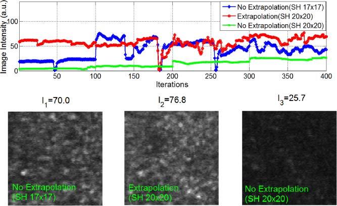
Experimental results with subject S2 (pupil size Φ6.5mm, SH 18 × 18). The blue curve represents image intensities obtained by AO imaging with the Φ6.12 mm sampling aperture (SH 17 × 17), while the red curve was the image intensity obtained with the boundary slope extrapolation algorithm (from the Φ6.5 mm pupil inscribed in the SH 18 × 18 grid to the Φ7.22 mm aperture inscribed in the SH 20 × 20 grid). The green curve shows the image intensity with the Φ7.22 mm sampling aperture (SH 20 × 20) without slope extrapolation. We can see that for a large SH grid (20 × 20) and a smaller eye pupil (Φ6.5mm), the AO control accuracy with slope extrapolation was higher than that without slope extrapolation, and it was more stable compared to the AO control using the optimal sampling aperture (SH 17 × 17). The large jumps in intensity arose from eye blinks.
4. Conclusion and discussion
For AO imaging there are not only mathematical issues in the solution of wavefront equation at the pupil edge, but for the human eye where the pupil does not retain a fixed size and position, there is a practical problem that the lenslets at the pupil edge may be partially filled, so the actual measurements we obtain at the boundary from the SH sensor may not be correct and may not perfectly reflect the conditions under which the influence matrix was calibrated. We therefore adjust the mirror actuators to compensate the non-existent aberrations. This fact aggravates the boundary effect in wavefront sensing and control. In this paper two related steps for controlling boundary wavefront slope errors were implemented and their impacts on human retinal imaging quantified. As shown in Figs. 3-7, a simple approach to avoid the boundary slope error effect was to reduce the sampling aperture size relative to the human pupil size, allowing the wavefront AO correction to produce excellent performance and was readily adapted to different sized pupils for different individuals. This approach should not be unique to the woofer-tweeter AO control we use, but should be a general property of systems where the eye’s pupil may be smaller than the system pupil or there may be instabilities at the edges of the system pupil (due to vignetting and actuator limitations at the edges of a mirror for instance). To test the generality, we also measured the boundary effect under different types of mirror control modes, including the successive dual DM AO modes (“Mirao held+BMC”, and “BMC held+Mirao”), and single DM AO modes (single Mirao, and single BMC) [18], and all showed the same conclusion as the simultaneous dual DM AO mode (Fig. 10 ).
Fig. 10.
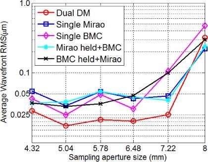
Plot of wavefront rms as a function of sampling aperture size for different AO modes with an artificial eye (physical pupil size Φ7.22mm). “Mirao held+BMC” mode: The Mirao DM was initially used for correction to converge, then the Mirao mirror profile was held and wavefront correction switched to the BMC DM AO mode. The “BMC held+Mirao” mode was similar to the “Mirao held+BMC” mode except that its dual DM AO correction sequence was in the opposite order [18].
To further improve the boundary condition and to better handle the wavefront error at the pupil edges, a slope-extrapolation algorithm was proposed to extend the slope data smoothly across the pupil boundary from inside pupil to outside the pupil in a real-time manner. Slope extrapolation makes the AO correction more stable and resistant to variations arising from slight head motions and pupil size change. With the human subject data in Fig. 9, we can see that image intensity with slope extrapolation was roughly the same as the best results obtained with a fixed pupil size without extrapolation, but produced the result more consistently during the viewing time. While the improvement was small and probably related to actual position of the subject during the run, the data were more stable, and on average the extrapolation approach produced a little better image quality. The two-step approach is important for handling the boundary condition in high resolution retinal imaging, especially in cases when the eye is moving or the pupil size fluctuating, which are common in human imaging.
Acknowledgments
This work was supported by NIH grants EY04395, EY14375 and P30EY019008.
References and links
- 1.Liang J., Williams D. R., Miller D. T., “Supernormal vision and high-resolution retinal imaging through adaptive optics,” J. Opt. Soc. Am. A 14(11), 2884–2892 (1997). 10.1364/JOSAA.14.002884 [DOI] [PubMed] [Google Scholar]
- 2.Tyler G. A., “Reconstruction and assessment of the least-squares and slope discrepancy components of the phase,” J. Opt. Soc. Am. A 17(10), 1828–1839 (2000). 10.1364/JOSAA.17.001828 [DOI] [PubMed] [Google Scholar]
- 3.Zou W., Zhang Z., “Generalized wave-front reconstruction algorithm applied in a Shack-Hartmann Test,” Appl. Opt. 39(2), 250–268 (2000). 10.1364/AO.39.000250 [DOI] [PubMed] [Google Scholar]
- 4.Han I. W., “New method for estimating wavefront from curvature signal by curve fitting,” Opt. Eng. 34(4), 1232–1237 (1995). 10.1117/12.196542 [DOI] [Google Scholar]
- 5.Acosta E., Rios S., Soto M., Voitsekhovich V. V., “Role of boundary measurements in curvature sensing,” Opt. Commun. 169(1-6), 59–62 (1999). 10.1016/S0030-4018(99)00428-9 [DOI] [Google Scholar]
- 6.Noll R. J., “Phase estimates from slope-type wavefront sensors,” J. Opt. Soc. Am. 68(1), 139–140 (1978). 10.1364/JOSA.68.000139 [DOI] [Google Scholar]
- 7.Reed Teague M., “Deterministic phase retrieval: a Green’s function solution,” J. Opt. Soc. Am. 73(11), 1434–1441 (1983). 10.1364/JOSA.73.001434 [DOI] [Google Scholar]
- 8.Woods S. C., Greenaway A. H., “Wave-front sensing by use of a Green’s function solution to the intensity transport equation,” J. Opt. Soc. Am. A 20(3), 508–512 (2003). 10.1364/JOSAA.20.000508 [DOI] [PubMed] [Google Scholar]
- 9.Roddier F., “Curvature sensing and compensation: a new concept in adaptive optics,” Appl. Opt. 27(7), 1223–1225 (1988). 10.1364/AO.27.001223 [DOI] [PubMed] [Google Scholar]
- 10.Roddier C., Roddier F., “Wave-front reconstruction from defocused images and the testing of ground-based optical telescopes,” J. Opt. Soc. Am. A 10(11), 2277–2287 (1993). 10.1364/JOSAA.10.002277 [DOI] [Google Scholar]
- 11.McLellan J. S., Prieto P. M., Marcos S., Burns S. A., “Effects of interactions among wave aberrations on optical image quality,” Vision Res. 46(18), 3009–3016 (2006). 10.1016/j.visres.2006.03.005 [DOI] [PMC free article] [PubMed] [Google Scholar]
- 12.Chen D. C., Jones S. M., Silva D. A., Olivier S. S., “High-resolution adaptive optics scanning laser ophthalmoscope with dual deformable mirrors,” J. Opt. Soc. Am. A 24(5), 1305–1312 (2007). 10.1364/JOSAA.24.001305 [DOI] [PubMed] [Google Scholar]
- 13.Zawadzki R. J., Choi S. S., Jones S. M., Oliver S. S., Werner J. S., “Adaptive optics-optical coherence tomography: optimizing visualization of microscopic retinal structures in three dimensions,” J. Opt. Soc. Am. A 24(5), 1373–1383 (2007). 10.1364/JOSAA.24.001373 [DOI] [PMC free article] [PubMed] [Google Scholar]
- 14.Zou W., Qi X., Burns S. A., “Wavefront-aberration sorting and correction for a dual-deformable-mirror adaptive-optics system,” Opt. Lett. 33(22), 2602–2604 (2008). 10.1364/OL.33.002602 [DOI] [PMC free article] [PubMed] [Google Scholar]
- 15.Cense B., Koperda E., Brown J. M., Kocaoglu O. P., Gao W., Jonnal R. S., Miller D. T., “Volumetric retinal imaging with ultrahigh-resolution spectral-domain optical coherence tomography and adaptive optics using two broadband light sources,” Opt. Express 17(5), 4095–4111 (2009). 10.1364/OE.17.004095 [DOI] [PMC free article] [PubMed] [Google Scholar]
- 16.Li C., Sredar N., Ivers K. M., Queener H., Porter J., “A correction algorithm to simultaneously control dual deformable mirrors in a woofer-tweeter adaptive optics system,” Opt. Express 18(16), 16671–16684 (2010). 10.1364/OE.18.016671 [DOI] [PMC free article] [PubMed] [Google Scholar]
- 17.Ferguson R. D., Zhong Z., Hammer D. X., Mujat M., Patel A. H., Deng C., Zou W., Burns S. A., “Adaptive optics scanning laser ophthalmoscope with integrated wide-field retinal imaging and tracking,” J. Opt. Soc. Am. A 27(11), A265–A277 (2010). 10.1364/JOSAA.27.00A265 [DOI] [PMC free article] [PubMed] [Google Scholar]
- 18.Zou W., Qi X., Burns S. A., “Woofer-tweeter adaptive optics scanning laser ophthalmoscopic imaging based on Lagrange-multiplier damped least-squares algorithm,” Biomed. Opt. Express 2(7), 1986–2004 (2011). 10.1364/BOE.2.001986 [DOI] [PMC free article] [PubMed] [Google Scholar]
- 19.Hofer H., Chen L., Yoon G.-Y., Singer B., Yamauchi Y., Williams D. R., “Improvement in retinal image quality with dynamic correction of the eye’s aberrations,” Opt. Express 8(11), 631–643 (2001). 10.1364/OE.8.000631 [DOI] [PubMed] [Google Scholar]
- 20.Roddier F., Roddier C., “Wavefront reconstruction using iterative Fourier transforms,” Appl. Opt. 30(11), 1325–1327 (1991). 10.1364/AO.30.001325 [DOI] [PubMed] [Google Scholar]
- 21.Poyneer L. A., Gavel D. T., Brase J. M., “Fast wave-front reconstruction in large adaptive optics systems with use of the Fourier transform,” J. Opt. Soc. Am. A 19(10), 2100–2111 (2002). 10.1364/JOSAA.19.002100 [DOI] [PubMed] [Google Scholar]
- 22.Zou W., Rolland J. P., “Iterative zonal wave-front estimation algorithm for optical testing with general-shaped pupils,” J. Opt. Soc. Am. A 22(5), 938–951 (2005). 10.1364/JOSAA.22.000938 [DOI] [PubMed] [Google Scholar]


