Abstract
Using cultured Aplysia neurons we recently reported on the development of a novel approach in which an extracellular, non-invasive multi-electrode-array system provides multisite, attenuated, intracellular recordings of subthreshold synaptic potentials, and action potentials (APs), the so called “IN-CELL” recording configuration (to differentiate it from intracellular recordings). Because of its non-invasive nature, the configuration can be used for long term semi intracellular electrophysiological monitoring of APs and synaptic potentials. Three principals converge to generate the IN-CELL configuration: (a) engulfment of approximately 1 μm size gold mushroom-shaped microelectrodes (gMμE) by the neurons, (b) formation of high seal resistance between the cell’s plasma membrane and the engulfed gMμE, and (c), autonomous localized increased conductance of the membrane patch facing the gMμE. Using dissociated rat hippocampal cultures we report here that the necessary morphological and ultrastructural relationships to generate the IN-CELL recording configuration are formed between hippocampal cells and the gMμEs. Interestingly, even <1 μm thin branches expand and engulf the gMμE structures. Recordings of spontaneous electrical activity revealed fast ∼2 ms, 0.04–0.75 mV positive monophasic APs (FPMP). We propose that the FPMP are attenuated APs generated by neurons that engulf gMμEs. Computer simulations of analog electrical circuits depicting the cell–gMμE configuration point out the parameters that should be altered to improve the neuron–gMμE electrical coupling.
Keywords: action potential, field potentials, multi-electrode-array, MEA, gold mushroom-shaped microelectrodes, electrical coupling
Introduction
Multiunit, non-invasive extracellular recordings by flat microelectrode arrays (MEAs) is currently the central electrophysiological methodology for long term analysis of in vitro and in vivo neuronal network activities (Fromherz, 2003, 2006; Berdondini et al., 2009; Maccione et al., 2010; Wheeler and Nam, 2011) These MEA also serve as a platform for drug neurotoxicity screening (for example Johnstone et al., 2010). Similar MEAs are also used for the development of brain–machine interfaces (Hochberg et al., 2006; Lebedev and Nicolelis, 2006). In fact, the extracellular MEA approach is the only available technology for high temporal resolution of multiunit electrical recordings and stimulation. It enables long term recordings of field potentials that reflect extracellular currents generated by neuronal action potentials (APs) in the vicinity of the electrodes and local field potentials (FPs) that reflect synchronized subthreshold activity generated by ensembles of nearby neurons (Einevoll et al., 2010). Despite the extensive research and development efforts, extracellular recordings provide no direct information on synaptic potentials. Furthermore, the analysis of FP requires extensive computations, which often relay on estimated parameters (Quiroga et al., 2004; Einevoll et al., 2010). On the other hand, with excellent signal-to-noise ratio, sharp-intracellular microelectrodes, and patch-electrodes enable to resolve subthreshold events including excitatory and inhibitory synaptic potentials as well as to analyze the mechanisms underlying the generation of APs. In addition, intracellular current injections through these electrodes serve to reliably stimulate individual neurons as well as to extract essential biophysical parameters such as input resistance, membrane capacitance, and analyze synaptic properties (e.g., reversal potentials). Nevertheless, the use of sharp or patch microelectrodes is limited to a relatively small number of neurons as the manipulation of the electrode tips toward target cells requires the use of bulky micromanipulators (but see Markram and Perin, 2011; Perin et al., 2011). In addition, the duration of intracellular recording and stimulation sessions by these electrodes is limited, since with time, mechanical instabilities damage the plasma membrane, or in the case of the patch electrodes perfusion of the cytoplasm alter the intracellular composition of the cells (Sakmann and Neher, 1984 but see Akaike and Harata, 1994).
Using cultured Aplysia neurons we reported in a recent series of publications on the development of a novel neuro-electronic interface that integrates the advantages of non-invasive extracellular electrodes and intracellular access to neurons (Spira et al., 2007; Hai et al., 2009a,b, 2010a,b). The method consists of an array of chemically functionalized non-invasive, micrometer sized, gold mushroom-shaped microelectrodes (gMμEs) that practically provide multisite, attenuated intracellular recordings of APs, and subthreshold synaptic potentials, while the electrodes maintain an extracellular position. We referred to this mode of recording and stimulation as the IN-CELL configuration to differentiate it from intracellular recording and stimulation. The IN-CELL configuration enables recording with quality and signal-to-noise ratio that matches recording by perforated patch-electrode (Akaike and Harata, 1994; Inyushin et al., 1997). The interface also supports “IN-CELL stimulation” by milliseconds long single pulses (Hai et al., 2010b). Consistent with the extracellular position of the gMμEs in respect to the cells, the recording sessions can last for days (Hai et al., 2010b).
Three cell biological processes converge to generate effective IN-CELL recording and stimulation configuration: (a) active engulfment of the gMμEs by the neurons, (b) the generation of high seal resistance between the neuron and the electrode and (c) localized increase in the conductance of the plasma membrane that faces the gMμE. The physical principles underlying the IN-CELL recording and stimulation are similar to those of the perforated patch clamp configuration (Akaike and Harata, 1994; Inyushin et al., 1997; Hai et al., 2010a,b).
The main objectives of the present study were to begin and examine the prospective to implement the IN-CELL configuration to cultured mammalian cells. It should be noted that the cell bodies and main neurites of isolated Aplysia neurons are significantly larger than vertebrate neurons and can be manually placed on top of chemically functionalized gMμE. This in turn leads to optimal positioning of the neuron’s cell bodies in respect to a number of gMμEs and their engulfment (Spira et al., 2007; Hai et al., 2009a,b). Here we asked whether primary mammalian cell bodies of 10–20 μm in diameter respond to the presence of a 1- to 2-μm size gMμEs by their engulfment. How would growing 1 μm thick neurites that extend from the cell bodies respond when encountering gMμEs? Would the neurites avoid the gMμEs structures and grow in between them or engulf them? Would the plasma membrane of the neurons form close physical contact with the gMμEs? And can the cells survive; develop excitable membrane properties and synaptic contacts when grown on a matrix of gMμE? What is the nature of the cells–gMμE electrical coupling?
We report here that: (a) the cell bodies and branches of cultured hippocampal cells (neurons and glia) engulf functionalized gMμEs. (b) The cell’s plasma membrane forms tight physical apposition with the gold surfaces to increase the seal resistance. (c) These parameters are sufficient to enable the recordings of mainly positive monophasic APs, with amplitude of 0.04–0.75 mV, spontaneously generated by the neurons, and monophasic slow potentials reaching amplitudes of approximately 5 mV, which might represent glial membrane potential shifts. Analysis of the results indicates that bioengineering the IN-CELL configuration for vertebrate neurons is feasible.
Materials and Methods
gMμE based MEA fabrication
Arrays of gMμE electrodes for electrical measurements were prepared on 200 μm thick glass wafers (AF45 Schott Glass) as previously described (Hai et al., 2009a, 2010b). Briefly, wafers were coated with a Ti (10 nm)/Au (100 nm) layer by way of evaporation, spin-coated with photoresist AZ-1505 (4,000 RPM) baked for 30 min (90°C) after which a first photolithographic process was performed to define the conduction lines by Au/Ti wet etch. Next a second lithographic step using S-1813G2 photoresist was performed to open holes for the deposition of the gMμE stalks as well as the contact pads. Next the gMμEs were formed by way of gold electroplating at current density of 0.15A/cm2 for 15–20 min. The photoresist layer was stripped off and a layer of silicon oxide (∼3,000 A) was deposited by chemical vapor deposition. This layer serves to passivate the conducting electrode lines. A third layer of photoresist was then applied. A third lithographic step was used to expose the contact pads and the caps of the gold mushrooms followed by wet oxide etch to selectively remove the oxide from the contact pads and the mushroom caps. Retrospective SEM of the gMμEs revealed that the oxide on the upper (third) part of the stalk was also etched. Wafers were then diced and underwent manual bonding to 62-pad printed circuit boards to which 21 mm glass rings were attached to create a recording bath chamber for the culturing medium.
Fabrication of gold mushroom-shaped micro protrusions matrixes
Scanning- and transmission-electron microscopic imaging were conducted using dissociated cultured hippocampal cells grown on matrices of gold mushroom-shaped protrusions (gMμP). The fabrication of gMμP matrixes were prepared on 200 μm glass wafers (AF45 Schott Glass) by means of photolithography and electroplating techniques, as described above.
The slides were attached to culture dishes using silicone (Sylgard Dow Corning).
Surface functionalization
Three different surfaces were used in accordance to the purpose of the experiment: (a) For immunolabeling observations we used plane cover slide substrate (Marienfeld, Germany). (b) For electron microscopy (SEM and TEM) we used gold mushroom based matrixes in which the substrate in between the electrodes was Au. This enabled us to label the surface of the glass substrate by electron opaque gold layer for its visualization and reduced the cost of chip fabrication for SEM imaging. (c) For electrophysiological recordings we used gold mushroom based MEA (as described above) in which the space between the electrodes was of SiO2. All three surfaces were functionalized by: Poly-d-Lysine (PDL) supplemented with laminin (Lam), or by polyethylenimine (PEI; Sigma Aldrich, MW > 300,000) or by the cysteine terminated engulfment promoting peptide (EPP; Spira et al., 2007; Hai et al., 2009a,b). Coating of the surfaces by PDL or by PEI supplemented with laminin (20 μg/ml) was done by application of 0.1% PDL or PEI in 0.1 M sodium borate to the culture dish as previously described (Soussou et al., 2007). Functionalization of the Au surfaces by the EPP was done by application of 1 mM peptide dissolved in phosphate buffer onto the surface at room temperature as previously described (Spira et al., 2007; Hai et al., 2009a).
Cell culture
Cell cultures were prepared from neonatal SD/Hsd rats as described (Gitler et al., 2004). Briefly, after decapitation, the hippocampi were removed, treated with papain (Sigma Aldrich), and serially triturated. Cell density at plating was 200,000–400,000 cells/ml. Cells were cultured in B27 supplemented Neurobasal medium (GIBCO) at 37°C in a humidified atmosphere of 5% CO2. All experiments were approved by the Committee for Animal Experimentation at the Institute of Life Sciences of the Hebrew University.
Electron microscopy
For both SEM and TEM analysis cells cultured on the gold mushroom substrate were fixed, dehydrated, and embedded in Agar 100 within the culturing dish as previously described (Spira et al., 2003). Briefly, hippocampal primary cultured cells were fixed by 3% glutaraldehyde in phosphate buffer at pH 6.9. The cells were then washed in phosphate buffer and then in 0.5 M cacodylate buffer, pH 7.4 (Agar Scientific, Stansted, England). The cells were post-fixed in 0.5% osmium tetroxide (Next Chimica, Centurion, South Africa) and 0.8% K3Fe(CN)6. Dehydration was carried out through a series of ethanol solutions. For TEM the neurons were embedded in Agar 100 (Agar Scientific, Stansted, England). Then the glass substrate was etched using 30% hydrofluoric acid (for ∼3 h). The Cr/Au layer was partially etched by diluted Au etcher (I2/KI/H2O) and diluted HF (1:40), leaving the gold mushroom structures intact. Thereafter, the agar block, including the cells was re-embedded in Agar 100 in a flat mold. This doubly embedded preparation was then thin-sectioned.
Measurements of cleft width from TEM images were done digitally using image analysis program ImageJ (NIH, USA). Each image was divided into three areas: (1) gold mushroom cap, (2) gold mushroom stalk, and (3) flat gold substrate in between the gold mushrooms. The sampling locations were selected within a grid (100 nm pitch) randomly placed on the image. The distance between the cell membrane and the mushroom was measured along the corresponding fraction of the grid lines.
Electrophysiology
For recording with commercially available flat MEAs we used the Multi Channel Systems (MCS, Reutlingen, Germany) electrode arrays (62 Ti/Au/TiN electrodes, 10 μm diameter, 200 μm spacing). Both commercial devices and gMμE devices were amplified by an AC, 60-channel amplifier (MEA-1060-Inv-BC, MCS) with frequency limits of 1–10,000 Hz.
Origin 8.1 software (OriginLab Corp., Northampton, MA, USA) was used to plot the results.
Computer simulation
Computer simulations were done using SPICE. For the simulations, the parameters used were: (1) the non-junctional membrane resistance (Rnj) which was measured in a large number of publications to range between 100 and 250 MΩ (Spruston and Johnston, 1992; Ambros-Ingerson and Holmes, 2005; Scorza et al., 2011) for neurons and 2–6 MΩ for glia (Murphy et al., 1993; Linden, 1997). (2) Junctional membrane resistance (Rj) was estimated from TEM images analysis. The contact area of the gMμE with the cells was estimated to be ∼10 μm2. This is only a fraction of the actual surface area of an averaged gMμE, which is estimated to be 12 μm2 (see Results). For the calculations of Rj we multiplied the total input resistance (Rin) with the ratio between the surface area of the neuron and the contact surface area of the gMμE. We estimated Rj for neurons to be ∼100 GΩ and for glia ∼5 GΩ. (3) The non-junctional membrane capacitance Cnj equals the total membrane capacitance Cm and was set to 100 pF for both neurons and glia. (4) The estimated junctional membrane capacitance (Cj) is calculated from the estimated contact area between the cells and the gMμE (10 μm2) and the value of specific membrane capacitance (1 μF/cm2) to be 0.1 pF. (5) The gMμE resistance (RgMμE) in solution was estimated to be 1,500 GΩ in accordance with the measured resistance of gold electrodes in physiological solution (McAdams et al., 2006; Hai et al., 2010a) normalized by the gMμE surface area. (6) The capacity of the gMμE in solution is estimated by taking the specific capacity of gold electrical double layer to be ∼50 μF/cm2 (Mirsky et al., 1997) multiplied by the surface area of the gMμE to be 5 pF. (7) The amplifier input capacitance is 8 pF (Multi Channel Systems, Reutlingen, Germany).
For the simulations, a short (2 ms) and a long (250 ms) square current pulses (2 nA) “were injected” into the simulated cell (between Rnj and Rj). The coupling coefficients were calculated as the voltage ratios between the amplitudes of simulated gMμE and the potential generated within the simulated cell.
Simulation of the shape of the voltage calibration pulse were done by applying a 20-ms, 1 mV voltage pulse to the “bathing solution” – between the simulated cell and ground.
Results
Biocompatibility of the protruding mushroom-shaped microstructures matrixes
We began the study by testing the compatibility of the gold mushroom protruding microstructures functionalized by different chemicals as substrates for culturing dissociated rat hippocampal cells. To that end we plated dissociated hippocampi on flat glass surfaces or on matrixes of gMμPs fabricated on glass sputtered by a thin film of gold (see Materials and Methods). The inter-gMμPs interval was 8 μm and they were functionalized by PDL, PDL/Lam, PEI, PEI/Lam, or EPP (as explained above).
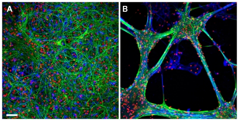
Differential interference microscopic observations complemented by retrospective immunolabeling revealed that the growth pattern of the hippocampal cells on PDL, PDL/Lam, PEI, or PEI/Lam were similar on the glass substrate and on the gMμP matrixes. In contrast, hippocampal cells grown on EPP functionalized substrates generated large aggregates in which the glia cells formed a sheet in contact with the substrate and the neurons grew on top (Figures A1A,B in Appendix). This configuration was mechanically unstable and easily detached from the surface. Immunolabeling of neurons by NF, glia cells by GFAP and nuclei by DAPI, revealed that the relative number of surviving neurons decreased over time (from 60% on day 5 to 25–35% on day 20) for all tested substrates. Hippocampal cells cultured on EPP functionalized matrixes generated aggregates and thus could not be counted.
Characterization of the structural relations between hippocampal cells and the gMμPs by scanning electron microscopy
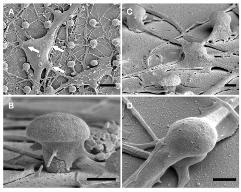
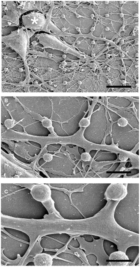
Scanning electron microscope images of dissociated cultured hippocampal cells on gMμP matrixes (Figures 1 and 2) revealed a number of cell morphologies. These most likely correspond to neuronal- and non-neuronal cells (Rothman and Cowan, 1981). According to earlier studies (Rothman and Cowan, 1981) the cell bodies of the non-neuronal cells assume in culture flat geometry and extend numerous branches while the neurons generate a distinctive long neurite, the axon, and a number of shorter branches the dendrites (Craig and Banker, 1994). Examination of SEM micrographs of cultured cells grown on PDL, or PEI, 5, 10, and 21 days after plating revealed that many cell bodies are localized on top of one to three gMμPs (Figure 1A). A single branch is often seen to contact a number of gMμPs (Figure 2). Images of the cell bodies or branch perimeters generated at an angle of 45° cannot provide a clear view of the interface formed between the cell body and the gMμP but suggest that the cell’s plasma membrane tightly adhere to the gMμP (Figures 1 and 2). Unexpectedly, we observed that even very thin branches with a diameter of 0.5–1 μm also engulf the gMμPs (Figure 1). The high incidence of extensive engulfment of the gMμPs by these thin neurites suggest that during the growth period, the growth cones at the leading tips of the extending neurites “recognize” the gMμP geometry, enlarge to encompass the structure, and then continue to grow.
Figure 1.
SEM images of dissociated cultured rat hippocampal cells grown on a matrix of gMμP functionalized with PEI for 6 days. (A) A low magnification showing a neuron (upper left) and a non-neuronal cell (lower right). The white arrows denote the location of three gMμPs residing below the neuron. (B) A close-up image of a single gMμP partially engulfed by a neurite. (C) Thin branches expand to engulf gMμPs. (D) A close-up image of thin branches engulfing a single gMμP. [Scale bars denote 5 μm for (A), 1 μm for (B–D)].
Figure 2.
SEM images of a single rat hippocampal neuron grown on a matrix of gMμP engulfing a number of gMμPs. The images were prepared from cultures grown on PEI for 6 days. (A) A low magnification micrograph showing three neurons and their neurites. (B,C) enlargements of the neurite extending from the cell body marked by an asterisk in (A). Note that this single neurite engulfs a number of gMμPs. [Scale bars denote 12, 5, and 2.5 μm for (A–C), respectively].
Occasional breaks in the branches on top of the gMμP reveal tight membrane-gold surface interfacing. SEM images generated from 5, 10, and 21 days old cultures revealed that a similar fraction of the engulfed gMμPs profiles is maintained over time. It is thus conceivable to assume that this mode of structural relationships between the neurites and the gMμPs is maintained for at least a number of weeks.
Characterization of the ultrastructural relationships between hippocampal cells and the gMμPs by transmission-electron microscopy
Whereas scanning electron micrographs provided general information on the physical contact formed between the cultured cells and the gMμPs, it does not provide details on the interfaces formed between the plasma membrane and the gMμP. We therefore turned to examine thin sections prepared from cultured hippocampal cells on gMμP matrixes for transmission-electron microscopy.
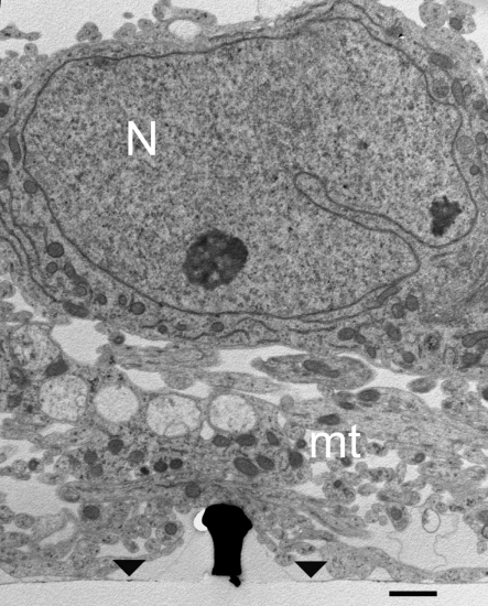
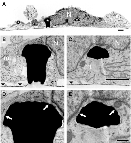
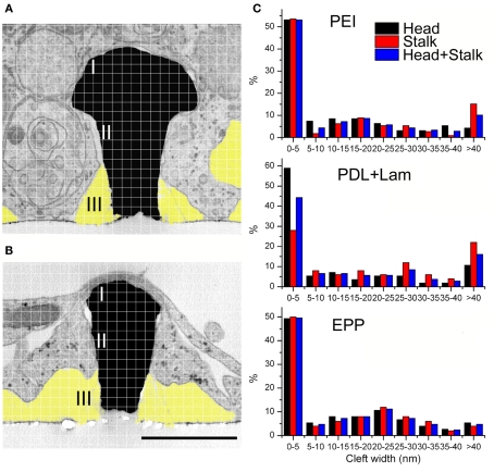
Examination of thin sections prepared from 5 to 21 days old cultures revealed that fractions of the spaces adjacent to the flat culture substrate are occupied by thin branches. As a consequence cell bodies residing on top of the branches cannot form physical contact with the gMμPs (Figure 3). Nevertheless, other cell bodies tightly adhere to the substrate and engulf a number of gMμPs (Figure 4). Consistent with the SEM images described above, branches are often seen to tightly enwrap and adhere to at least parts of the gMμP (Figure 1B). In many cases the branches adhere to the mushroom cap and to parts of the “mushrooms stalks” leaving other parts of the gMμP stalk in contact with large extracellular space (Figure 5). Using TEM images (as illustrated by Figures 4 and 5) we measured the cleft width formed between the cell’s membrane and the “cap” and “stalk” of the gMμP functionalized by PDL, PEI, and EPP (Figures 5A,B). We found that under these conditions approximately 50% of the cell–gMμP interface areas appear to be in direct contact with the electrode surface (defined as 0–5 nm cleft). The rest 40% of the interface reveals a cleft of 5–40 nm. The remaining 10% of the gMμP surface area is in contact with extracellular space that is larger than 40 nm (Figure 5C).
Figure 3.
TEM image of cultured hippocampal cells grown on a matrix of gMμPs functionalized by PEI. Low magnification image revealing that in some parts of the cultures the cell bodies reside on top of a layer of branches that do not form direct physical contact with the gMμPs. Note that only a small part of the shown gold mushrooms “cap” is in contact with the branches. Images are from a 10-days old culture. N, Nucleus; mt, mitochondria; area of flat gold substrate-arrowheads. Scale bar: 1 μm.
Figure 4.
TEM images of a cultured hippocampal cell engulfing three gMμPs. (A) A low magnification micrograph of a cell body engulfing three gMμPs (asterisks). (B–E) enlargements of the junctions formed between the cell and two of the gMμPs. The arrows in (D,E) point to regions of tight apposition between the cell’s plasma membrane and the PEI functionalized surface of the gMμPs. Images are from a 10-days old culture. N, Nucleus; mt, mitochondria; the horizontal straight lines in (B,C) depict area of flat gold substrate-arrowheads. Scale bar for (A–C) 1 μm and for (D,E) 250 nm.
Figure 5.
Analysis of the cleft width formed between hippocampal cells grown on functionalized matrixes of gMμPs. For the experiments the gMμPs were functionalized by PEI, PDL + laminin, and the engulfment promoting peptide EPP. (A,B) The cleft width was measured along two areas, the surface of the mushrooms’ “cap” (marked I), and along the upper part of the stalk (marked II). Measurements were conducted at points defined by a randomly placed grid on a TEM image. In the majority of the TEM images the lower part of the gold mushroom’s stalk was not tightly engulfed and not measured (marked III, yellow). Ruptured agar, appearing as clear white areas in the TEM images, were not included in the analysis (see text). Calibration 1 μm. (C) Independent of the chemical functionalization, the cleft width along the mushrooms cap surface was close to zero. Along the upper part of the stalk the gap was ≪ 40 nm, and along the lower part of the stalk ≫ 40 nm.
It should be noted that the measured extracellular cleft width formed between the cells plasma membrane and the gMμP could reflect osmotic pressure artifacts generated during the chemical fixation, dehydration, and embedding processes (Studer et al., 2008). Nevertheless, as the subcellular organelles (mitochondria, vesicles, the endoplasmic reticulum, and the plasma membrane, (Figures 3–5) are well preserved it is unlikely that the fixation and embedding procedures generated significant osmotic pressure artifacts. It is important to note in this respect that the presence of electron translucent breaks in the embedding material, mainly at the curving junctions between the cells and the gMμP cap as well as the stalk (for example on the left hand side of the gMμP in Figure 3) are generated during the TEM observations by the detachment of the embedding polymer (Agar 100) from the gold structures.
An alternative explanation to the tight interface between the cell’s membrane and the gMμP could be mechanical tension generated by cytoskeletal elements in response to the curvature of the gMμP (McMahon and Gallop, 2005; Hai et al., 2009a).
The morphometric values obtained from the electron micrographs were used to estimate the seal resistance formed between the plasma membrane and the device (for details see Appendix). For the estimate the mushroom cap and stalk diameters were taken as 2 and 1 μm respectively and the height of the stalk 1 μm. For the model we assumed that the tight contact between the cell’s membrane and the gMμP is formed only along the upper third of the stalk. With these values we obtained that Rseal is ∼53 MΩ. Because of the large variability in the interface area between the cells and the gMμPs we estimate that Rseal ranges between 10 and 100 MΩ.
Estimate of the seal resistance generated by the cells and the gMμPs in living material
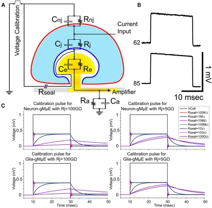
As Rseal is one of the most important physical parameters that define the electrical coupling between neurons and the sensing gMμPs, and being concerned that osmotic pressure artifacts could affect the morphometric measurements, we next estimated Rseal in living cultures (unfixed) by the use of a calibration electrical pulse. To that end we examined the time constant of a square voltage calibration pulse delivered to the bathing solution and recorded by the individual gMμEs (Figures 6A,B). As depicted by the analog electrical circuit (Figure 6A) the simulation of the time constant of a calibration pulse as “seen” by the gMμE is sensitive to the value of Rseal. Comparison of the simulations and the results obtained from individual cell-gMμE junctions corroborate that the seal resistances generated between the cells and gMμE is ≤100 MΩ (Figures 6B,C). This estimate is in rough agreement to the value obtained from the ultrastructural studies.
Figure 6.
Estimation of the seal resistance by the shape of the voltage calibration pulse. Using the analog electrical circuit depicting the gMμE – hippocampal cells junction (A), we simulated the expected shape of a 1-mV voltage calibration pulse delivered to the bathing solution (voltage calibration) and compared it to the actual recorded calibration pulse by the gMμE. (B) depicts the experimentally recorded voltage calibration of Figure 7 (neuron, 62) and that of Figure 8 (electrode 85). (C) The electrical parameters to simulate a neuron and a tentative glia cell are given in the Section “Materials and Methods.” The simulation was conducted for neurons and tentative glia with Rj of 100 GΩ and 5 GΩ, while the seal resistance Rseal was altered from 100 kΩ to 100 GΩ (see color coding). The voltage calibration pulse (1 mV) delivered to the bathing solution and recorded by the gMμE is depicted in black. Note that in the simulation the time constant of the calibration pulses as seen by the gMμE, depends on the value of Rseal and the junctional membrane resistance. The time constant of the experimentally recorded calibration pulses is shorter than the simulated for Rseal = 100 MΩ. In the schematic drawing RgMμE and CgMμE are depicted by Re and Ce respectively. Ra and Ca are the amplifier resistance and capacitance respectively. Note: the downward drift of the experimentally recorded calibration pulse (electrode 62 and 85) is due to the properties of the AC amplifier used (charged is leaking to the ground). The simulation model depicts a DC amplifier.
Recording of spontaneous electrical activity by gMμE MEA
The gMμEs based MEAs used in this study are composed of 8 × 8 gMμEs with cap diameter of 1–2 μm2 and pitch of 20 μm covering a recording surface area of 147 μm × 147 μm (∼2,1000 μm2). The flat surface in between the gMμEs is glass. The relatively small surface area covered by the gMμEs based MEA and the small surface area of individual gMμEs limit the number of cells and neurites from which recordings are expected. Recording of spontaneous electrical activity was made from 10 to 20 days old cultures. Successful recordings were occasionally made as early as 5 days after plating. Typically, the background noise level of the system was of ∼20 μV. In all experiments a 20-ms 1 mV voltage calibration square pulse was applied to the bathing solution by an isolated pulse generator. To compare the recordings made by the gMμEs and planar electrodes we used the commercially available 8 × 8 planar MEA with electrode diameter of 10 μm and surface area of 314 μm2 (Multi Channel System, Reutlingen Germany).
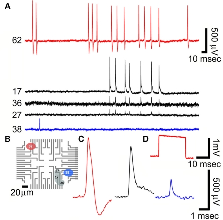
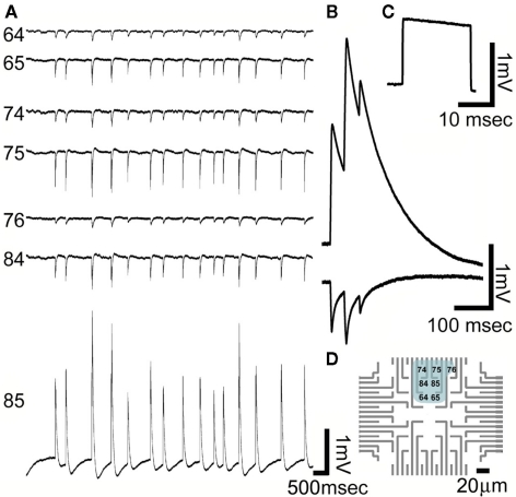
Because of the small dimensions of the gMμEs most individual electrodes were in contact with a single cell as depicted in the SEM micrographs (Figures 1 and 2) and indicated by the relatively uniform shape and amplitude of the recorded potentials by a given gMμE (Figures 7 and 8). Recordings of spontaneous activity were made with wide band filter of 1–10 kHz. Based on the duration of the discreet spontaneous potentials and their shape we subdivided the recorded activities to fast positive monophasic potentials (FPMP), and long-lasting potentials (LLP). FPMP last ∼2 ms with amplitudes ranging between 0.04 and 0.75 mV (Figure 8), and LLP last >50 ms with amplitudes ranging between 0.1 and 5 mV (Figure 9).
Figure 7.
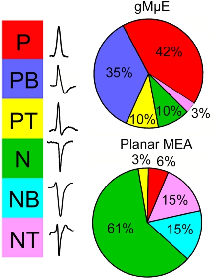
Categorization of the dominant spike waveforms detected by planar and gMμE based MEA. The waveforms of spontaneous spikes recorded by planar and gMμE based MEA were sorted by their dominant positive or negative polarity and shape to monophasic, biphasic, and triphasic. Note that whereas the majority of the waveforms recorded by the planar MEA are of negative going spikes, the recorded potentials by the gMμE based MEA are positive. P, positive spike; PB, positive bi-phase spike; PT, positive tri-phase spike; N, negative spike; NB, negative bi-phase spike; NT, negative tri-phase spike.
Figure 8.
Recordings of spontaneous fast monophasic positive action potentials (FMPP) generated by cultured hippocampal neurons grown on a PEI functionalized gMμEs based MEA for 10 days. (A) Spontaneous trains of FPMP generated by three neurons (one coupled to electrode 62, the second coupled to three electrodes 17, 36, and 27 and the third to electrode 38). The distance between electrodes 27 and 36 is approximately 40 μm. (B) The location of the electrodes that picked up the spike activity is depicted on a schematic layout of the MEA. (C) The potential recorded by electrodes 62, 17, and 38 in (A) are enlarged. (D) A 1-mV, 20 ms square calibration pulse delivered to the bathing solution and recorded by electrode 62.
Figure 9.
Recordings of spontaneous long-lasting potentials (LLP) presumably generated by cultured glia cells grown on PEI functionalized gMμEs based MEA for 10 days. (A) Spontaneous synchronized LLPs recorded by seven gMμEs. Six gMμEs recorded synchronized monophasic negative going potentials (electrode number 64, 65, 74, 75, 76, and 84) while one electrode (85) recorded mirror image positive going potentials. (B) Enlargement of the mirror image LLPs recorded by electrodes 85 and 75. (C) A calibration pulse of 1 mV 20 ms. As recorded by electrode 85 (D) The location of the gMμEs that picked up the LLPs is depicted on a schematic layout of the MEA. Note that the cell generating these LLPs extends over an area of approximately 60 μm × 60 μm.
To gain some insight to the nature of coupling between neurons and the gMμE we compared the shapes of spontaneous potentials recorded by the gMμE MEA and those recorded by the planar MEA. To that end both types were functionalized by PEI and cultured for the same duration. The comparison revealed a number of differences.
In contrast to the recordings obtained from planar MEA in which the spontaneous firing of APs generate field potentials dominated by negative peaks (Figure 7, and see for discussion Jenkner and Fromherz, 1997; Fromherz, 2003; Nam et al., 2006; Cohen et al., 2008; Wheeler and Nam, 2011), the FPMP recorded by the gMμE MEA were dominated by positive peaks (Figures 7 and 8). The significant differences in the dominant spike polarity between planar MEA and gMμE based MEA could be accounted for in two ways: (a) since negative field potentials reflect local extracellular inward currents and positive field potential outward current, it is conceivable that flat electrodes recorded mainly from axons and excitable soma, while the gMμEs recorded outward currents from unexcitable compartments such as the dendrites or inexcitable cell bodies (Claverol-Tinture and Pine, 2002; Wheeler and Nam, 2011). Alternatively (b), it is conceivable to assume that the seal resistance generated by the neurons-gMμE configuration is much larger than that formed with planar electrodes and that the membranes facing the gMμE express conducting ion channels. Thus, attenuated, intracellular APs were in fact recorded by the gMμEs (Jenkner and Fromherz, 1997; Claverol-Tinture and Pine, 2002; Fromherz, 2003; Cohen et al., 2008; Hai et al., 2010a,b; Wheeler and Nam, 2011). These hypothesizes will be further discussed below.
In addition to the FPMP, spontaneous LLP were recorded by the gMμE based MEA (Figure 9). The amplitude of the LLP range between 0.1 and 5 mV and last for >50 ms. They were monophasic either positive or negative (Figure 8). Using the gMμE MEA we recorded concomitant LLP by a number of neighboring gMμEs. In some cases one gMμE recorded a positive LLP while its nearby gMμEs recorded negative monophasic mirror image LLPs of smaller amplitude (Figure 9 for further discussion of the LLP see below).
Discussion
The main finding of the present study is that cultured rat hippocampal cells (neurons and possibly glia) tightly engulf chemically functionalized 1–2 μm sized gMμE that extend from a flat surface. A single cell body can engulf up to three gMμEs. Surprisingly thin <1 μm branches that extend from the cell bodies expand to engulf gMμEs forming a junction of close membrane apposition over a large fraction of the gMμE. As suggested by the SEM images, neurites that engulf a gMμE continue to extend and grow to form physical contact with a number of gMμEs. Based on electrophysiological criteria a single cell may form electrical coupling with up to seven neighboring gMμEs spaced at a distance of 20 μm (Figure 9). TEM micrographs revealed that approximately 50% of the contact area formed between a cell and a chemically functionalized gMμE appears to almost totally exclude the extracellular space, 40% of the contact area is characterized by a gap of <40 nm and 10% by a gap >40 nm. The ultrastructure of the tight physical contact formed by the cells and the gMμEs is similar to that reported by our laboratory for cultured Aplysia neurons, and a number of cell lines (Chinese Hamster Ovary cells – CHO, embryonic fibroblast cells-NIH/3T3, rat adrenal medulla cells-PC-12, and rat myocardium cells-H9C2; Hai et al., 2009a).
Using morphological criteria, it is impossible to unequivocally differentiate between neurons, glia, or other cell types in culture. Nevertheless, using retrospective immunolabeling of neurons and glia we found that 10–20 days old cultures are composed of ∼50% neurons and 50% of astrocytes.
The recorded spontaneous potentials could be subdivided into two categories of FPMPs and LLPs. As the duration of the recorded FPMPs is similar to intracellularly recorded APs generated by neurons, and as the LLPs fits the time course of glial membrane potential shifts, we tentatively propose that the FPMP represent attenuated APs generated by neurons and the positive and negative going LLPs represent IN-CELL and extracellular recordings of glia cells.
As the purpose of the current paper is to establish a starting point for future application of the IN-CELL recording configuration to cultured vertebrate neurons, we have not investigated yet the mechanisms underlying the generation of LLPs. However, we tentatively wish to propose in the following paragraph the possibility that the LLPs are recorded from glia cells.
It is unlikely that LLP electrical pattern can be generated by highly synchronized synaptic activity (local field potentials) among dissociated cultured neurons. It is also unlikely to be the consequence of summation of trains of APs. The tentative hypothesis that LLPs could be generated by glia is consistent with what is known on astrocytes membrane potential shifts. It is well established that glia sense local changes in the extracellular potassium concentrations and express receptors that are activated by “spillover” of various neurotransmitters released by neurons (For review see Schipke and Kettenmann, 2004; Halassa and Haydon, 2010; Velez-Fort et al., 2011). The LLPs recorded by the gMμEs clearly differ from the fast field potentials generated by spiking neurons in their duration (for example Murphy et al., 1993). Interestingly the amplitude of the positive LLPs (up to 5 mV) is in the range of measured astrocytes potential shifts by patch electrodes (Orkand et al., 1966; Murphy et al., 1993; Mennerick and Zorumski, 1994; Mennerick et al., 1996). The observation of synchronized mirror image single positive LLP and multiple negative spontaneous LLPs recorded by a number of neighboring electrodes (Figure 9) could theoretically represent a configuration in which: (a) All the recording electrodes are extracellular. If this is the case we have to assume that the multiple electrodes that record negative potentials are located on branches that are synchronously activated to generate inward current and the single electrode that records positive current represent a compartment in which the currents flow out. An alternative interpretation (b), is that the positive potential represent IN-CELL recording from a glia cell body and the mirror image negative potentials represent extracellular recordings made from branches that engulf gMμEs. (c) Theoretically, although less likely, is the possibility that the LLPs are generated by synchronized firing of a group of neurons (or a combination of neurons and glia) that together form heterogeneous seal resistances over a group of gMμEs.
To the best of our knowledge the literature using MEA for the analysis of culture network activity has not dealt with such LLPs. This might be due to deliberate limitation of data acquisition and analysis by frequency filters selective for APs which last 1–2 ms. Nevertheless, using planar MEA systems, we occasionally recorded LLPs.
Estimation of the seal resistance
The results described in the present study raise questions as to the prospective of applying the IN-CELL recording configuration to cultured vertebrate neurons. In contrast to the case of Aplysia neurons and vertebrate cell lines in which the cell bodies that engulf the gold mushroom’s cap and stalk also tightly adhere to the flat substrate in between the microelectrodes (Spira et al., 2007; Hai et al., 2009a), in dissociated hippocampus cultures extensive growth of branches mechanically interfere with adhesion of the cells to the substrate (Figure 3).
Based on measurements of the cleft dimensions, the dimensions of the contact area and the size of the gMμEs as well as with the aids of the calibration pulse analysis we estimated the seal resistance to be ≤100 MΩ (see Appendix and Figure 6). As discussed earlier (Jenkner and Fromherz, 1997; Fromherz, 2003, 2006; Cohen et al., 2008; Hai et al., 2010a,b) and elaborated on later, increasing the seal resistance to the GΩ levels would be very beneficial for the improvement of the electrical coupling between the cells and the gMμEs.
Analog electrical circuit simulation of the coupling coefficient between cells and the gMμEs
The electrical coupling between cells and microelectronic devices depends on the physical parameters depicted in the analog electrical circuit of Figure 6A. In the following we first explain the parameters comprising the analog electrical circuit for cultured hippocampal neurons and glia cells and then, using an electrical circuit simulation system (SPICE), examine the expected electrical coupling between model neurons and glia and the gMμEs. The estimated values are then compared to the results and used to evaluate the alterations that should be introduced to the experimental system to improve the electrical coupling.
The model (Figure 6A) depicts the passive elements of a cell membrane (neuron or astrocytes), the extracellular space and the gMμE. The cell membrane is composed of a non-junctional membrane characterized by a passive RC circuit with parameters (Rnj; Cnj) and a junctional membrane facing the gMμE (Rj; Cj). The cleft formed between the neuron’s plasma membrane and the surface of the gMμE and extends toward the bulk of the solution (Rseal) and the gMμE (Re = RgMμE and Ce = CgMμE). The majority of parameters used for the simulation were obtained from published experimental results and estimations of the physical parameters to fit the geometry and dimensions of the gMμE and the neuron–gMμE interface (see Table 1 for the values used and the Appendix for their estimations).
Table 1.
Electrical parameters used to simulates the coupling coefficient between the cells (Neurons and glia) and the gold mushroom shaped microelectrodes.
| Parameter | Neuron | Glia |
|---|---|---|
| Non-junctional membrane resistance – Rnj | 100 MΩ | 5 MΩ |
| Non-junctional membrane capacitance – Cnj | 100 pF | 100 pF |
| Junctional membrane resistance – Rj | 100 GΩ | 5 GΩ |
| Junctional membrane capacitance – Cj | 0.1 pF | 0.1 pF |
| Resistance of the gMμE – RgMμE | 1,500 GΩ | 1,500 GΩ |
| Capacitance of the gMμE – CgMμE | 5 pF | 5 PF |
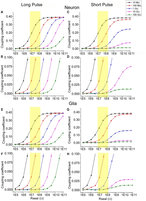
Simulation of the coupling coefficient for high frequencies of 500 Hz (simulating APs) and long pulses (250 ms square pulses) were obtained by current injection (2 nA) into the “neurons” and “glia” with parameters shown in Table 1 and as a function of Rseal using different values for the junctional membrane resistance (Figure 10).
Figure 10.
Simulation of the estimated coupling coefficient between neurons or glia with gMμEs. For the simulation we used the electrical circuit depicted in Figure 6. The simulation was conducted by injection of a long [250 ms (A,B,E,F)] and short [2 ms (C,D,G,H)] square current pulse. (A–D) simulation of the electrical coupling coefficient of a neuron and a gMμEs as a function of Rseal, (E–H) simulation of the coupling coefficient between a tentative glia cell and a gMμEs as a function of Rseal (in Ohms) at various Rj ranging between 100 GΩ and 10 MΩ (see color coding). (B,D,F,H) are respective y-zooms into (A,C,E,G). The yellow squares emphasize the expected coupling coefficient values when Rseal is set to the values estimated by the experiments in the range of 10–100 MΩ. The expected coupling coefficient for neurons and glia cells with junctional resistance of 10–100 GΩ is given by the Y-axis values corresponding to the red line within the yellow box.
Given that Rseal is in the range of 10–100 MΩ (our results, yellow boxes in Figure 10.) and Rj is 5–100 GΩ (red and black in Figure 10 and see Appendix), the simulations reveal that the coupling coefficient for a short or a long injected current pulses ranges between ∼0.05 and ∼0.2. To improve the coupling coefficient to a desirable level of being able to record intracellular synaptic potentials of ∼1 mV the minimal coupling coefficient should be somewhat larger than 0.2. If Rseal is not improved and remains in the range of 10–100 MΩ, Rj has to be reduced by two to three orders of magnitude from an estimated value of 10–100 GΩ to 100 MΩ. If the seal resistance can be elevated to values of hundreds of gigaohm, the junctional resistance does not have to be altered.
The simulation of a glia cell, which differs from a neuron by its lower Rnj (in the range of 5 MΩ, Murphy et al., 1993; Linden, 1997), and therefore by a lower Rj (∼5 GΩ), revealed that the estimated electrical coupling coefficient is similar to that estimated for the neurons. The experimental results revealed however almost tenfold higher recordings amplitudes of the positive LLPs than the FMPP (Figures 8 and 9). These observations suggest that either the Rj value of the cells generating the LLPs is lower than that estimated by us for the calculations, or that the value of Rseal is higher than used in the model (or that both parameters are in fact involved). Assuming that the LLP are indeed IN-CELL recordings of intracellular glial transmembrane potentials (that are reported in the experimental literature to be in the range of the 1- to 10-mV), we have to assume that the coupling coefficient between the glia and the gMμE is in the order of 0.5. Theoretically to reach such value Rj has to be lower than 10 MΩ (Figure 10). Such a low value could be obtained if the cell either recruit ion channels into the patch of membrane facing the gMμE as suggested and discussed by us in earlier publications (Hai et al., 2010a,b), or that because of the geometry of the gMμE the curved junctional membrane generate nano-holes and thereby locally increase the membrane conductance.
In conclusion, the experimental results and analysis of the interface formed between dissociated hippocampal cells and gMμE based MEA suggest that the recorded FPMP represent attenuated APs generated by the neurons. To improve the coupling coefficient between the neurons and the electrodes either Rj has to be reduced or Rseal increased. Attenuation of Rj could be achieved by inducing the recruitment of voltage-independent ion channels to the junctional membrane by appropriate chemical functionalization of the gMμE. The results tentatively suggest that PEI or PDL functionalized gMμE based MEAs might interface glia cells with the electrodes to generate IN-CELL recordings.
Conflict of Interest Statement
The authors declare that the research was conducted in the absence of any commercial or financial relationships that could be construed as a potential conflict of interest.
Acknowledgments
Parts of the study were carried out at the Charles E. Smith and Prof. Elkes Laboratory for Collaborative Research in Psychobiology. M. E. Spira is the Levi DeViali Professor in neurobiology.
Appendix
In this section we explain the parameters and values used in the analog electrical circuit of hippocampal cells–gMμE interface model.
Neuronal membrane parameters
The non-junctional membrane resistance (Rnj) was estimated in a number of experimental studies. The input resistance (Rin) values for cultured hippocampal neurons is in the range of 100–250 MΩ (Scorza et al., 2011). We selected to use in the model the value of 100 MΩ. The input resistance of the glial cell was taken as 5 MΩ (Murphy et al., 1993; Linden, 1997). Since the surface area of the junctional membrane (Rj) is negligible in respect to the cell surface area, Rnj and the input resistance (Rin) in both neurons and glia can be considered as equal.
For the estimation of the junctional membrane resistance (Rj) we first estimated the engulfed surface area of the gMμEs. To that end we modeled a gMμE with cylinder-shaped stalk of 1 μm in diameter and stalk height of 1 μm. The mushroom’s cap (modeled as half a ball) diameter is 2 μm. Based on the electron micrographs we assumed that the cells engulf the mushrooms cap and only the upper third of the stalk which is denoted as hstalk.
The engulfed area of the gMμE is given by:
Rrim = the surface area under the mushroom
Where:
Using the values given above, we obtain that the total area of the gMμE electrode is 11.8 μm2 and the engulfed area is 9.81 μm2 for the estimation we used
Dividing the value of the neuron capacitance of C = 100 pF by the universal value of the specific membrane capacitance Cs = 1 μF/cm2, we obtain an estimated value of the neuron’s surface area
Next, we multiplied the total input resistance (Rin) with the ratio between the surface area of the neuron (Aneuron) and the surface area of the cells plasma membrane in contact with the gMμE thus:
Using the same considerations the glial Rj ≈ 5 GΩ.
The non-junctional membrane capacitance for both neurons and glia-Cnj equals the total membrane capacitance Cm and was set to 100 pF.
The junctional membrane capacitance Cj is estimated from the plasma membrane engulfing surface area of 10 μm2 to be 0.1 pF.
gMμE and amplifier parameters
The gMμE resistance (RgMμE) in solution was estimated to be 1,000 GΩ for mushroom surface area of ∼14 μm2 (Hai et al., 2010a). In this work, as a result of gMμE smaller dimensions, we estimated the values of RgMμE:
The capacitance of the gMμE in solution is estimated by taking the specific capacitance of gold electrical double layer (CEDL) to be ∼50 μF/cm2 (Mirsky et al., 1997) multiplied by the surface area of the gMμE (AgMμE) given above yielding:
The amplifier input capacitance is 8 pF (Multichannel systems, Rutlingen, Germany).
The seal resistance
The seal resistance (Rseal) is generated by the solution within the gap confined between the surface of the gMμEs and the engulfing cell membrane and extends from the center to the cap of the gMμEs to the point in the stalk were the tight engulfment is terminated (top third of the stalk). It consists of three resistors in series.
The resistor depicting the gap formed between the cap surface and the cell membrane.
The resistor of the cap bottom rim.
The resistor of the stalk.
In reality the combination of the capacitors and seal resistance is a distributed network.
For the sake of simplicity we replace it with discrete elements circuit in which we calculate the seal resistance by assuming that its starting point is an imaginary circle on the cap which divides the capacitance of the gMμEs into two equal parts.
Following are the calculations of the three segments:
Mushroom cap
The model is based on the integration of the resistors of concentric rings on the cap starting at angle α and ending at angle of π/2. The result of the integration is:
ρ is the solution resistivity, ρ = 100 Ωcm, t is the cleft thickness, t = 5 nm.
α is determined by the above considerations, i.e., that the cap capacitance up to α is equal to the sum of the capacitance of the cap from α to π/2 plus the bottom rim capacitance plus the stalk capacitance.
Figure A1.
The growth pattern of the hippocampal cells on poly-d-lysine/laminin versus EPP. Retrospective immunolabeling of 20 days old hippocampal cells grown on poly-d-lysine (A) and EPP (B): neurons (green), glial cells (blue), counterstained with nuclear marker DAPI (red). Scale bar: 50 μm. Neurons were labeled for neuron-specific intermediate filaments with mouse anti NF antibodies followed by goat anti-mouse secondary antibodies conjugated to Cyanine 2 (Cy2). Glial cells were labeled for glial fibrillary acidic proteins with primary anti-GFAP rabbit monoclonal antibodies followed by goat anti-rabbit secondary antibodies conjugated to Cy3. Confocal imaging was done using D-Eclipse C1 imaging system (Nikon) mounted on an Eclipse TE-2000 microscope (Nikon). Images were collected and processed using EZ-C1 software (Nikon). Scanning was done in sequential mode: red was excited with 543 nm He–Ne laser and collected with 605 ± 75 band pass filter; green was excited with 488 nm Argon laser and collected with 515 ± 30 band pass filter; blue excited with 405 nm Diode and collected with 450 ± 35 band pass filter. Images were prepared using the open-source image analysis program ImageJ (NIH, USA). Hippocampal cells grown on the EPP clustered to form bundles and aggregates in which the glia cells formed a sheet in contact with the substrate and the neurons grew on top. Cells in different aggregates interconnect by thick fascicles emanating from clusters and projecting to adjacent aggregates.
The cap surface area from its center till angle α is given by:
The rest of the capacitor area is given by:
From the arbitrary definition that S1 = S2 and the values of all other parameters as given above, the value of α is estimated to be 77.3°. Inserting this value in the equation of R1 yields R1 = 7.1 MΩ. The other two contributions to Rseal are:
Inserting the parameters given above, results in:
References
- Akaike N., Harata N. (1994). Nystatin perforated patch recording and its applications to analyses of intracellular mechanisms. Jpn. J. Physiol. 44, 433–473 10.2170/jjphysiol.44.433 [DOI] [PubMed] [Google Scholar]
- Ambros-Ingerson J., Holmes W. R. (2005). Analysis and comparison of morphological reconstructions of hippocampal field CA1 pyramidal cells. Hippocampus 15, 302–315 10.1002/hipo.20051 [DOI] [PubMed] [Google Scholar]
- Berdondini L., Massobrio P., Chiappalone M., Tedesco M., Imfeld K., Maccione A., Gandolfo M., Koudelka-Hep M., Martinoia S. (2009). Extracellular recordings from locally dense microelectrode arrays coupled to dissociated cortical cultures. J. Neurosci. Methods 177, 386–396 10.1016/j.jneumeth.2008.10.032 [DOI] [PubMed] [Google Scholar]
- Claverol-Tinture E., Pine J. (2002). Extracellular potentials in low-density dissociated neuronal cultures. J. Neurosci. Methods 117, 13–21 10.1016/S0165-0270(02)00043-2 [DOI] [PubMed] [Google Scholar]
- Cohen A., Shappir J., Yitzchaik S., Spira M. E. (2008). Reversible transition of extracellular field potential recordings to intracellular recordings of action potentials generated by neurons grown on transistors. Biosens. Bioelectron. 23, 811–819 10.1016/j.bios.2007.08.027 [DOI] [PubMed] [Google Scholar]
- Craig A. M., Banker G. (1994). Neuronal polarity. Annu. Rev. Neurosci. 17, 267–310 10.1146/annurev.ne.17.030194.001411 [DOI] [PubMed] [Google Scholar]
- Einevoll G. T., Wojcik D. K., Destexhe A. (2010). Modeling extracellular potentials. J. Comput. Neurosci. 29, 367–369 10.1007/s10827-010-0283-y [DOI] [PMC free article] [PubMed] [Google Scholar]
- Fromherz P. (2003). Neuroelectronic Interfacing: Semiconductor Chips with Ion Channels, Nerve Cells, and Brain. Berlin: Wiley-VCH; [DOI] [PubMed] [Google Scholar]
- Fromherz P. (2006). Three levels of neuroelectronic interfacing: silicon chips with ion channels, nerve cells, and brain tissue. Ann. N. Y. Acad. Sci. 1093, 143–160 10.1196/annals.1382.011 [DOI] [PubMed] [Google Scholar]
- Gitler D., Xu Y., Kao H. T., Lin D., Lim S., Feng J., Greengard P., Augustine G. J. (2004). Molecular determinants of synapsin targeting to presynaptic terminals. J. Neurosci. 24, 3711–3720 10.1523/JNEUROSCI.3795-04.2004 [DOI] [PMC free article] [PubMed] [Google Scholar]
- Hai A., Dormann A., Shappir J., Yitzchaik S., Bartic C., Borghs G., Langedijk J. P., Spira M. E. (2009a). Spine-shaped gold protrusions improve the adherence and electrical coupling of neurons with the surface of micro-electronic devices. J. R. Soc. Interface 6, 1153–1165 10.1098/rsif.2009.0087 [DOI] [PMC free article] [PubMed] [Google Scholar]
- Hai A., Kamber D., Malkinson G., Erez H., Mazurski N., Shappir J., Spira M. E. (2009b). Changing gears from chemical adhesion of cells to flat substrata toward engulfment of micro-protrusions by active mechanisms. J. Neural Eng. 6, 066009. 10.1088/1741-2560/6/6/066009 [DOI] [PubMed] [Google Scholar]
- Hai A., Shappir J., Spira M. E. (2010a). In-cell recordings by extracellular microelectrodes. Nat. Methods 7, 200–202 10.1038/nmeth.1420 [DOI] [PubMed] [Google Scholar]
- Hai A., Shappir J., Spira M. E. (2010b). Long-term, multisite, parallel, in-cell recording and stimulation by an array of extracellular microelectrodes. J. Neurophysiol. 104, 559–568 10.1152/jn.00265.2010 [DOI] [PubMed] [Google Scholar]
- Halassa M. M., Haydon P. G. (2010). Integrated brain circuits: astrocytic networks modulate neuronal activity and behavior. Annu. Rev. Physiol. 72, 335–355 10.1146/annurev-physiol-021909-135843 [DOI] [PMC free article] [PubMed] [Google Scholar]
- Hochberg L. R., Serruya M. D., Friehs G. M., Mukand J. A., Saleh M., Caplan A. H., Branner A., Chen D., Penn R. D., Donoghue J. P. (2006). Neuronal ensemble control of prosthetic devices by a human with tetraplegia. Nature 442, 164–171 10.1038/nature04970 [DOI] [PubMed] [Google Scholar]
- Inyushin M., Tsytsarev V., Ignashchenkova A., Lenkov D. N. (1997). Use of artificial ion channels for quasi-intracellular recording of cerebral cortex neuron activity. Neurosci. Behav. Physiol. 27, 702–707 10.1007/BF02461932 [DOI] [PubMed] [Google Scholar]
- Jenkner M., Fromherz P. (1997). Bistability of membrane conductance in cell adhesion observed in a neuron transistor. Phys. Rev. Lett. 79, 4705–4708 10.1103/PhysRevLett.79.4705 [DOI] [Google Scholar]
- Johnstone A. F., Gross G. W., Weiss D. G., Schroeder O. H., Gramowski A., Shafer T. J. (2010). Microelectrode arrays: a physiologically based neurotoxicity testing platform for the 21st century. Neurotoxicology 31, 331–350 10.1016/j.neuro.2010.04.001 [DOI] [PubMed] [Google Scholar]
- Lebedev M. A., Nicolelis M. A. (2006). Brain-machine interfaces: past, present and future. Trends Neurosci. 29, 536–546 10.1016/j.tins.2006.07.004 [DOI] [PubMed] [Google Scholar]
- Linden D. J. (1997). Long-term potentiation of glial synaptic currents in cerebellar culture. Neuron 18, 983–994 10.1016/S0896-6273(00)80337-2 [DOI] [PubMed] [Google Scholar]
- Maccione A., Gandolfo M., Tedesco M., Nieus T., Imfeld K., Martinoia S., Berdondini L. (2010). Experimental investigation on spontaneously active hippocampal cultures recorded by means of high-density MEAs: analysis of the spatial resolution effects. Front. Neuroeng. 3:4. 10.3389/fneng.2010.00004 [DOI] [PMC free article] [PubMed] [Google Scholar]
- Markram H., Perin R. (2011). Innate neural assemblies for lego memory. Front. Neural Circuits 5:6. 10.3389/fncir.2011.00006 [DOI] [PMC free article] [PubMed] [Google Scholar]
- McAdams E. T., Jossinet J., Subramanian R., McCauley R. G. (2006). Characterization of gold electrodes in phosphate buffered saline solution by impedance and noise measurements for biological applications. Conf. Proc. IEEE Eng. Med. Biol. Soc. 1, 4594–4597 10.1109/IEMBS.2006.260406 [DOI] [PubMed] [Google Scholar]
- McMahon H. T., Gallop J. L. (2005). Membrane curvature and mechanisms of dynamic cell membrane remodelling. Nature 438, 590–596 10.1038/nature04396 [DOI] [PubMed] [Google Scholar]
- Mennerick S., Benz A., Zorumski C. F. (1996). Components of glial responses to exogenous and synaptic glutamate in rat hippocampal microcultures. J. Neurosci. 16, 55–64 [DOI] [PMC free article] [PubMed] [Google Scholar]
- Mennerick S., Zorumski C. F. (1994). Glial contributions to excitatory neurotransmission in cultured hippocampal cells. Nature 368, 59–62 10.1038/368059a0 [DOI] [PubMed] [Google Scholar]
- Mirsky V. M., Riepl M., Wolfbeis O. S. (1997). Capacitive monitoring of protein immobilization and antigen-antibody reactions on monomolecular alkylthiol films on gold electrodes. Biosens Bioelectron 12, 977–989 10.1016/S0956-5663(97)00053-5 [DOI] [PubMed] [Google Scholar]
- Murphy T. H., Blatter L. A., Wier W. G., Baraban J. M. (1993). Rapid communication between neurons and astrocytes in primary cortical cultures. J. Neurosci. 13, 2672–2679 [DOI] [PMC free article] [PubMed] [Google Scholar]
- Nam Y., Branch D. W., Wheeler B. C. (2006). Epoxy-silane linking of biomolecules is simple and effective for patterning neuronal cultures. Biosens. Bioelectron. 22, 589–597 10.1016/j.bios.2006.01.027 [DOI] [PubMed] [Google Scholar]
- Orkand R. K., Nicholls J. G., Kuffler S. W. (1966). Effect of nerve impulses on the membrane potential of glial cells in the central nervous system of amphibia. J. Neurophysiol. 29, 788–806 [DOI] [PubMed] [Google Scholar]
- Perin R., Berger T. K., Markram H. (2011). A synaptic organizing principle for cortical neuronal groups. Proc. Natl. Acad. Sci. U.S.A. 108, 5419–5424 10.1073/pnas.1016051108 [DOI] [PMC free article] [PubMed] [Google Scholar]
- Quiroga R. Q., Nadasdy Z., Ben-Shaul Y. (2004). Unsupervised spike detection and sorting with wavelets and superparamagnetic clustering. Neural. Comput. 16, 1661–1687 10.1162/089976604774201631 [DOI] [PubMed] [Google Scholar]
- Rothman S., Cowan W. M. (1981). A scanning electron microscope study of the in vitro development of dissociated hippocampal cells. J. Comp. Neurol. 195, 141–155 10.1002/cne.901950108 [DOI] [PubMed] [Google Scholar]
- Sakmann B., Neher E. (1984). Patch clamp techniques for studying ionic channels in excitable membranes. Annu. Rev. Physiol. 46, 455–472 10.1146/annurev.ph.46.030184.002323 [DOI] [PubMed] [Google Scholar]
- Schipke C. G., Kettenmann H. (2004). Astrocyte responses to neuronal activity. Glia 47, 226–232 10.1002/glia.20029 [DOI] [PubMed] [Google Scholar]
- Scorza C. A., Araujo B. H., Leite L. A., Torres L. B., Otalora L. F., Oliveira M. S., Garrido-Sanabria E. R., Cavalheiro E. A. (2011). Morphological and electrophysiological properties of pyramidal-like neurons in the stratum oriens of Cornu ammonis 1 and Cornu ammonis 2 area of Proechimys. Neuroscience 177, 252–268 10.1016/j.neuroscience.2010.12.054 [DOI] [PubMed] [Google Scholar]
- Soussou W. V., Yoon G. J., Brinton R. D., Berger T. W. (2007). Neuronal network morphology and electrophysiologyof hippocampal neurons cultured on surface-treated multielectrode arrays. IEEE Trans. Biomed. Eng. 54, 1309–1320 10.1109/TBME.2006.889195 [DOI] [PubMed] [Google Scholar]
- Spira M. E., Kamber D., Dormann A., Cohen A., Bartic C., Borghs G., Langedijk J. P. M., Yitzchaik S., Shabthai K., Shappir J. (2007). “Improved neuronal adhesion to the surface of electronic device by engulfment of protruding micro-nails fabricated on the chip surface, Vols 1 and 2,” in Transducers ‘07 & Eurosensors Xxi, Digest of Technical Papers, U628, Lyon [Google Scholar]
- Spira M. E., Oren R., Dormann A., Gitler D. (2003). Critical calpain-dependent ultrastructural alterations underlie the transformation of an axonal segment into a growth cone after axotomy of cultured Aplysia neurons. J. Comp. Neurol. 457, 293–312 10.1002/cne.10569 [DOI] [PubMed] [Google Scholar]
- Spruston N., Johnston D. (1992). Perforated patch-clamp analysis of the passive membrane properties of three classes of hippocampal neurons. J. Neurophysiol. 67, 508–529 [DOI] [PubMed] [Google Scholar]
- Studer D., Humbel B. M., Chiquet M. (2008). Electron microscopy of high pressure frozen samples: bridging the gap between cellular ultrastructure and atomic resolution. Histochem. Cell Biol. 130, 877–889 10.1007/s00418-008-0500-1 [DOI] [PubMed] [Google Scholar]
- Velez-Fort M., Audinat E., Angulo M. C. (2011). Central role of GABA in neuron-glia interactions. Neuroscientist. 10.1077/107385841103317 [DOI] [PubMed] [Google Scholar]
- Wheeler B. C., Nam Y. (2011). In vitro microelectrode array technology and neural recordings. Crit. Rev. Biomed. Eng. 39, 45–61 [DOI] [PubMed] [Google Scholar]


