Abstract
Recent work has demonstrated that enzymatic degradation of collagen fibers exhibits strain-dependent kinetics. Conceptualizing how the strain dependence affects remodeling of collagenous tissues is vital to our understanding of collagen management in native and bioengineered tissues. As a first step towards this goal, the current study puts forward a multiscale model for enzymatic degradation and remodeling of collagen networks for two sample geometries we routinely use in experiments as model tissues. The multiscale model, driven by microstructural data from an enzymatic decay experiment, includes an exponential strain-dependent kinetic relation for degradation and constant growth. For a dogbone sample under uniaxial load, the model predicted that the distribution of fiber diameters would spread over the course of degradation because of variation in individual fiber load. In a cross-shaped sample, the central region, which experiences smaller, more isotropic loads, showed more decay and less spread in fiber diameter compared to the arms. There was also a slight shift in average orientation in different regions of the cruciform.
Keywords: tissue mechanics, remodeling, matrix metalloproteinase, multiscale
1 Introduction
Throughout life, the tissues of the body change in response to various environmental cues. The fundamental processes of growth and remodeling are essential for proper development of the individual and for healing following injury or disease. Examples include development of the embryonic heart (Nerurkar et al., 2006) and brain (Varner et al., 2010), post-infarction cardiac remodeling (Weber, 1997; Holmes et al., 2005), dermal wound healing and scarring (Madden and Peacock Jr, 1971; Cumming et al., 2010), and vascular remodeling (Adiguzel et al., 2009; Galis and Khatri, 2002; Taber and Humphrey, 2001). The evolution of bioengineered tissues follows a similar course (Robinson et al., 2008; Sander and Barocas, 2008; Sacks et al., 2009). The underlying processes are poorly understood and involve complex biochemical, bioelectrical, and biomechanical interactions between cells and extracellular matrix (ECM). Great progress toward understanding these interactions has been made using models that treat the tissue, including its constituent ECM, as a continuum (Ramasubramanian and Taber, 2008) or using a fiber-population-based model (Driessen et al., 2008; Kuhl et al., 2005). Cell-ECM interactions, however, are coordinated both locally and globally, such that changes in the microenvironment produce cell-directed organizational and compositional tissue adaptation. It is therefore desirable that one considers a model with a more realistic representation of the tissue architecture.
In native and engineered load-bearing soft tissues, the primary ECM component that resists tensile load is fibrillar collagen, in particular types I and III, forming into fibrils, fibers and, depending on the tissue, more complex, hierarchical structures. Networks, particularly unstructured networks, show very different behavior from structured networks (Chandran and Barocas, 2006; Sander et al., 2010; Sastry et al., 1998; Stein et al., 2008). Most importantly among these, the unstructured network has far greater potential for fiber rearrangement under load, which leads to certain characteristic features in contrast to structured networks: greater fiber rotation (Chandran and Barocas, 2006); smaller fiber stretches vis-à-vis the tissue stretch, especially in uniaxial loading (Sander et al., 2009b); greater variation in stretch among fibers (Chandran and Barocas, 2004); and large Poisson's ratios in tension (Stylianopoulos and Barocas, 2007b).
The distribution of fiber stretches may be critical to microstructural remodeling in a tissue. There are a number of enzymes that degrade ECM proteins, notably the matrix metalloproteinases (MMPs). MMPs are a family of mammalian proteases that degrade various constituents of the ECM and participate in the turnover of type I collagen (Lauer-Fields et al., 2002; Pardo and Selman, 2005). Bacterial collagenases (BC) have also been shown to degrade type I collagen, though with less specificity, and are often used in vitro to study the effects of enzymatic degradation on ECM proteins (Ruberti and Hallab, 2005). Recent work (Bhole et al., 2009; Flynn et al., 2010) has shown that MMP8 and BC kinetics for the degradation of reconstituted and native type I collagen fibers are strain dependent. Results from Bhole et al.'s micrometer-scale study exploring the strain dependent effects of BC on type I collagen fibers were directly used in the development of our present multiscale fiber degradation model. In the study, Bhole et al. used a novel in vitro method to measure the radial degradation of reconstituted type I collagen fibers by BC (Bhole et al., 2009). The method employed a microliter-scale reaction chamber in which reconstituted collagen networks were mechanically strained using a set of functionalized micropipettes while the networks were immersed in a highly concentrated BC solution. Dynamic changes in fiber diameter were then measured using microscopic differential interference contrast imaging to determine the strain dependence of fiber degradation.
In summary, two key observations motivate this work: (1) the mechanical environment within a complex tissue can vary from fiber to fiber, and (2) the MMP-mediated degradation of a collagen fiber is dependent on that mechanical environment. Thus, the objective of the current study was to conduct a preliminary exploration of how a model tissue might evolve under strain-dependent remodeling conditions.
2 Methods
2.1 Multiscale Model Implementation
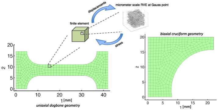
Simulations of remodeling within a collagen network were implemented using a deterministic multiscale mechanical model. The model linked the volume-averaged stress in micrometer-scale representative volume elements (RVEs) to a millimeter-scale finite element (FE) continuum. The general concept is illustrated in Fig. 1. Hexahedral elements with linear shape functions (8 Gauss points per element) comprised the FE domain. Each element was assigned a unique RVE, and RVE networks at each Gauss point within the element were updated discretely during the simulation. RVEs were comprised of a network of several hundred discrete type I collagen fibers within a cubic unit volume. Displacements were communicated from the continuum scale to the microscopic scale as boundary conditions on the RVE domain, and the resulting stresses were communicated to the continuum scale as a volume-averaged stress over the domain. The model iterated between both scales until the microscopic-scale and the macroscopic-scale force balances were satisfied. The model has been used previously to simulate the mechanics of collagen-based materials (Luo et al., 2009; Sander et al., 2009a; Stylianopoulos and Barocas, 2007a). In the current study, the model was modified to include strain-dependent collagen fiber decay and constant-rate fiber growth as described in Section 2.2.
Fig. 1.
Simulation geometries and overview of the multiscale model. In the multiscale model, displacements were communicated from the continuum scale to the microscopic scale as boundary conditions on the RVE domain, and the resulting stresses were communicated to the continuum scale as a volume-averaged stress over the domain.
Each RVE within the model was created using a stochastic fiber growth algorithm (Chandran and Barocas, 2006; Sander et al., 2009b). Fibers were grown from a random set of seed points that intersected to form cross-links. A typical RVE is shown in Fig. 1. For the present study, RVEs contained a mean of 1,007 fibers and had an edge length of roughly 30 μm. Fibers within the RVE (either in extension or contraction) were governed by the exponential force-strain constitutive relation:
| (2.1) |
where Ffiber is the resultant force along a fiber, Efiber is the Young's modulus for a fiber at infinitesimal strain, Afiber is the fiber cross-sectional area, εG is the fiber Green strain, and B is a fitting parameter. The relation was adapted from a previous fiber-based soft tissue model (Billiar and Sacks, 2000) and has been used in prior multiscale simulations (Stylianopoulos and Barocas, 2007b; Sander et al., 2009b). For the present study, a value of 79 MPa was used for Efiber, a value of 1.2 for B, and Afiber was calculated from an initial fiber diameter of 100 nm, based on a previous analysis of collagen gels (Stylianopoulos and Barocas, 2007b).
At each simulation step, the displacement field that yields mechanical equilibrium within the continuum is determined iteratively. At the macroscale, the material properties of the FE continuum were derived from the mechanical response of RVEs at Gauss points within each element. Based on the macroscale deformation of the FE continuum, the volume-averaged Cauchy stress was calculated for each RVE (Chandran and Barocas, 2007):
| (2.2) |
In this equation σ is the macroscale averaged Cauchy stress, σL is the local microscale stress, V is the RVE volume, bc indicates a discrete summation over all RVE boundary fiber cross-links, x is the boundary fiber cross-link coordinate, f is the force acting on the boundary fiber cross-link, and index notation is used. The continuum force balance based on the volume-averaged stress is given by (Chandran and Barocas, 2007):
| (2.3) |
In this relation n is the normal vector to the RVE boundary and u is the displacement of the RVE boundary. For more details see Stylianopoulos and Barocas (2007b).
2.2 Enzymatic Decay and Constant Growth Model
Strain-dependent fiber decay and constant fiber growth kinematic expressions were incorporated into the multiscale mechanical model to simulate remodeling within a collagen network over time. As a starting point, the following strain-dependent kinetic expression governing fiber decay was implemented:
| (2.4) |
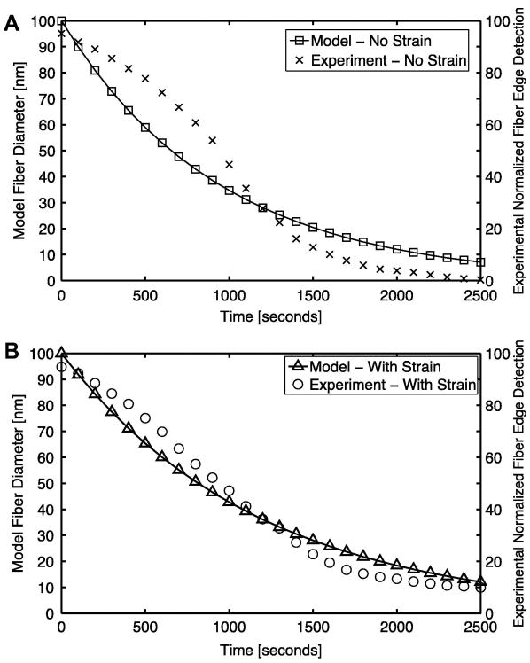
The expression is a function of fiber radius, r, and fiber stretch, λfiber (where λfiber > 1 in extension and λfiber < 1 in contraction), and contains two kinetic parameters, k1 and k2. The expression was fit to a set of experimental results for the degradation of a micrometer-scale collagen network via bacterial collagenase (BC) as seen in Fig. 2 (Bhole et al., 2009). Using the strain-free decay experimental case (where λfiber = 1), model parameter k1 was first fit to a value of 10.5×10⁻⁴ nm/sec by iteratively minimizing the sum of squared error between model and experimental fiber diameter (determined in the experiment via differential interference contrast microscopy) (Bhole et al., 2009). Parameter k2 was then fit to a unitless value of 0.83 using the experimental case where the network was held under strain. For this fit, a simulated microscale RVE network was held at a constant 25% stretch. All fibers within the RVE were set to an initial diameter of 100 nm and the fiber decay expression was then applied to fibers to simulate exposure to BC for 2500 seconds. The sum of squared errors in diameter between model and experiment was then minimized iteratively. It is noted that the fit is not particularly good, suggesting that a more accurate model could be developed, but the simple exponential decay model was chosen for this initial study.
Fig 2.
Change in the microscale model fiber diameter over time fit to the experimental normalized fiber edge detection results (normalized measure of the experimental fiber diameter) from Bhole et. al (2009) for the (A) unstrained and (B) strained case. The loss of fiber diameter is due to enzymatic decay via bacterial collagenase.
A constant-rate radial growth parameter was later added to Eq. 2.4 to simulate coupled growth and decay of collagen fibers. This constant-rate growth with strain-dependent decay kinetic expression was:
| (2.5) |
In this relation, the constant-rate growth parameter k3 was set to a trial value of 0.10 nm/sec and was implemented to gauge the response of the system to the simultaneous growth and decay of fibers. This trial value for k3 was chosen to ensure that the system would be in a state of net growth throughout the duration of the simulation.
Both kinetic expressions in Eq. 2.4 and Eq. 2.5 impact the mechanics of RVE fibers within the model that are governed by the fiber constitutive relation given in Eq. 2.1. A change in a fiber's radius, r, over time by decay and growth will change its effective cross-sectional area, Afiber, which is utilized in the fiber's constitutive relation. The fiber stretch, λfiber, that drives the kinetic expressions for fiber degradation is used in calculating the fiber Green strain, εG, which is also utilized in the fiber constitutive relation. These fiber-level expressions in turn impact the macroscale stress field via the volume-averaged stress for an RVE that is determined by the volume-averaging relation given previously in Eq. 2.2 (Chandran and Barocas, 2007).
2.3 Case Studies
Constant-force uniaxial extension and constant-strain biaxial extension simulations were implemented over a time course of 2,500 seconds with two distinct geometries for the decay and growth scenarios. For the constant-force uniaxial simulations, a dogbone geometry with a 290-element / 2,320-RVE mesh was used. The dogbone had a maximum length of 42.0 mm in the direction of loading, 17.0 mm in width, and 2.0 mm in thickness, as shown in Fig. 1. For the constant-strain equibiaxial extension simulations, a cruciform with a 316-element / 2,528-RVE mesh was used. One quadrant of the cruciform, with symmetry boundary conditions, was used with maximum axial dimensions of 22.0 mm and 20.0 mm, and a thickness of 1.0 mm, as shown in Fig. 1. The cruciform had an arm width ratio of 1:2, with the sample grip in axis 1 measuring 4.0 mm on its edge, and the sample grip in axis 2 measuring 8.0 mm. This geometry was chosen to be consistent with previous experimental and computational studies (Sander et al., 2009b; Jhun et al., 2009). The mesh discretization was tested against a refined 1172-element uniaxial mesh and resulted in a mean grip-to-grip Green strain difference of only 0.19% versus the 290-element mesh over a 1000-second fixed force uniaxial hold with decay, ensuring that the chosen mesh discretization was sufficiently refined for the present study.
For each simulation, all fibers were set to an initial diameter of 100 nm. The sample was then strained incrementally to the target grip force or extension, and the decay and growth kinetic relations were applied over a time course of 2,500 seconds. Four distinct simulations were conducted for the study: (1) uniaxial decay with a fixed grip force of 0.2 N, (2) uniaxial decay with a fixed grip force of 0.4 N, (3) biaxial decay with a fixed equibiaxial strain of 30%, and (4) biaxial growth with decay with a fixed equibiaxial stretch of 30%.
At each simulation step, all discrete microscale fiber positions, fiber lengths, and fiber diameters in the simulation were recorded for analysis, along with the macroscale FE nodal positions, Cauchy stress, and grip forces. Uniaxial simulations contained approximately 2,300,000 discrete fibers, and biaxial extension simulations contained approximately 2,600,000 discrete fibers. After simulations were completed, fiber and RVE statistics were calculated. As a measure of stiffness, selected RVEs were stretched uniaxially by 25%. The normal Cauchy stress in the axis of strain was taken as a measure of the network stiffness in that dimension. The diagonal components of the mass-weighted fiber orientation tensor, Ω, for RVEs were also calculated for analysis using the expression:
| (2.6) |
The expression was summed over each fiber in the network where mfiber is the mass of the fiber, mtotal is the total fiber mass in the network, n is the unit vector pointing along the fiber, and index notation was used (Stylianopoulos and Barocas, 2007b; Sander and Barocas, 2009c). All simulations were implemented using a custom C code (utilizing MPI message passing) on a 30-core sub-cluster at the Minnesota Supercomputing Institute. Each simulation had a wall time of approximately 14 hours. All post-processing and data analysis was done using MATLAB (Natick, MA).
3 Results
3.1 Constant-force uniaxial extension with strain-dependent enzymatic decay
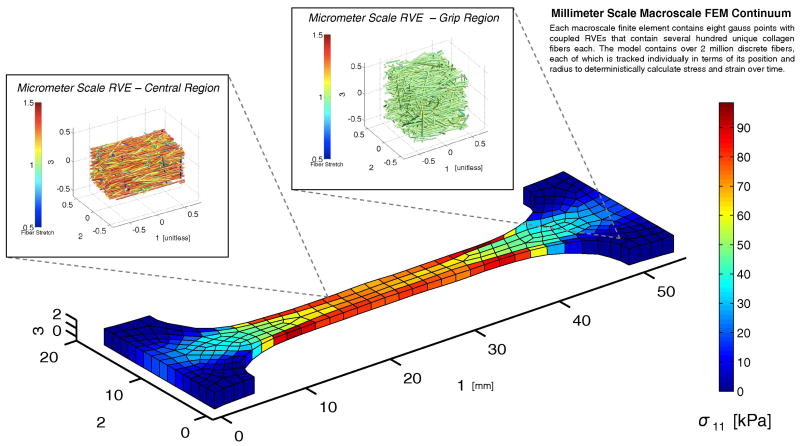
The 0.2 N uniaxial extension experiment on a dogbone is shown in Fig. 3. The stress was, as expected, fairly uniform in the center of the dogbone but with some stretch dependent heterogeneity. Networks in the central gauge region of the sample became highly aligned in the direction of stretch, and the sample became considerably thinner, consistent with our previous theoretical work (Stylianopoulos and Barocas, 2007b) and experimental studies on collagen gels in tension (Lake and Barocas, 2011). A network near the grip, shown for comparison, experienced less stress and less rearrangement.
Fig 3.
The σ11 Cauchy stress plotted over the deformed macroscale mesh for the uniaxial 0.2-N fixed force with enzymatic decay simulation case at t = 500 seconds. RVEs from two selected macroscale elements in the central and grip regions of the sample are plotted in their deformed configuration depicting fiber stretch within individual RVE networks.
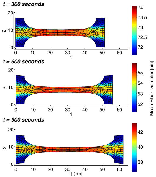
A snapshot from the enzyme-induced creep of the sample is shown in Fig. 4. As the fibers were degraded by the enzyme, the sample lengthened over time, thinning further in the central gauge region. The average fiber diameter in each element decreased with time but remained nearly uniform over the central region, indicating that average fiber stretches were consistent locally. The regional element-to-element variation in Fig. 4 is due to individual differences in the networks at each Gauss point in the mesh. That is, the slight inhomogeneity of the fiber networks led to a slight inhomogeneity in degradation rate.
Fig 4.
Mean fiber diameter per element plotted over the deformed mesh for the uniaxial fixed 0.2-N force hold with enzymatic decay simulation at t = 300, t = 600, and t = 900 seconds.
The network-level changes are seen more clearly in histograms of fiber diameters for a set of RVEs from the central gauge region of the sample (Fig. 5). Recalling that the initial fiber distribution was a delta function (s.d. = 0) at r = 100 nm, we see a steady spread of the distribution over time to a value of 5.89 nm at t = 1500. The spread resulted from different fibers within the network being under different loads, which in turn led to different degradation rates. Thus, fibers at low loads degraded quickly, producing the low-radius end of the distribution and separating from those at higher loads, which degraded more slowly. The global spread in fiber diameter is also apparent by evaluating average diameter in the sample over time (Fig. 4). Again, areas with diminished fiber stretch, such as in the peripheries of the grip region, experienced increased degradation as compared with the central gauge region.
Fig 5.
Fiber diameter histograms at t = 500, t = 1000, and t = 1500 seconds for the 0.2-N uniaxial fixed force with enzymatic decay simulation for n = 24 RVEs within the central gauge region of the dogbone sample.
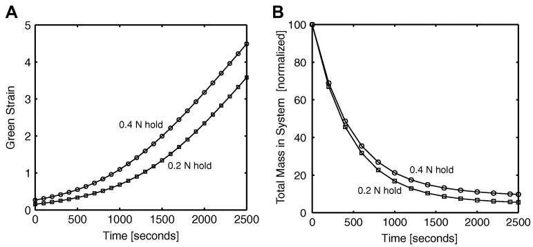
When the load was changed to 0.4 N, two major effects were observed, as can be seen in Fig. 6. In both cases, the sample strain increased monotonically with time, and the 0.4 N load sample stretched more than the 0.2 N sample (Fig. 6a), but the ratio between the two decreased over time due to greater mass loss in the 0.2 N case (Fig. 6b). Early on, the two samples degraded at nearly the same rate, but as strains in the 0.4 N case got larger, its degradation rate slowed down, leading to a smaller difference in tissue strain between the two cases.
Fig 6.
(A) the macroscale Green strain in the 1 direction over time for the uniaxial dogbone fixed force with enzymatic decay simulations. Two different hold forces were implemented. The Green strain was calculated using the reference sample length from grip-to-grip. (B) Decay in mass over time for the uniaxial enzymatic decay case for the 0.2-N and 0.4-N fixed force holds.
3.2 Constant-strain equibiaxial extension with strain-dependent enzymatic decay
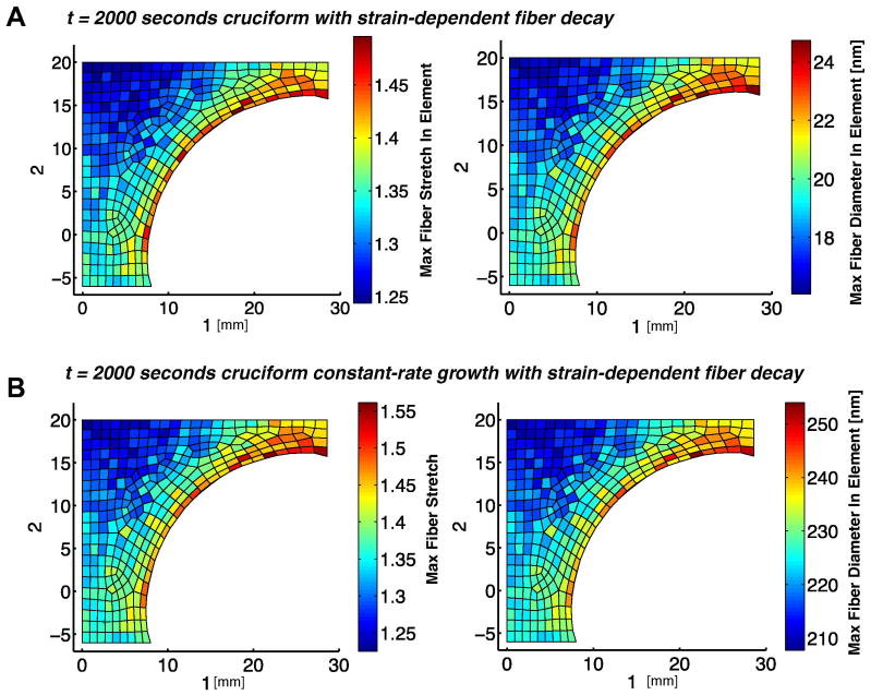
In the second set of simulations, the model was used to simulate the mechanics of a more complex and more tissue-like loading environment using one quadrant of a 1:2 arm-ratio cruciform sample. A fixed 30% equibiaxial stretch was applied to the cruciform that was then exposed to enzymatic decay. The resultant maximum fiber stretch per element is plotted alongside the maximum fiber diameter per element in Fig. 7a. Areas with collagen fibers experiencing the greatest fiber stretch coincided with areas with the greatest fiber diameter. As compared with the uniform loading and fiber stretch in the center of the uniaxial dogbone geometry, the cruciform geometry produced more pronounced inhomogeneity in fiber stretch and loading.
Fig 7.
Maximum fiber stretch per element as compared alongside the maximum fiber diameter per element for the (A) decay only and (B) constant-rate growth (k3=0.10 nm/sec) with strain-dependent enzymatic decay case. In both simulations the sample is held at a 30% equibiaxial stretch. The initial fiber diameter for the model was 100 nm.
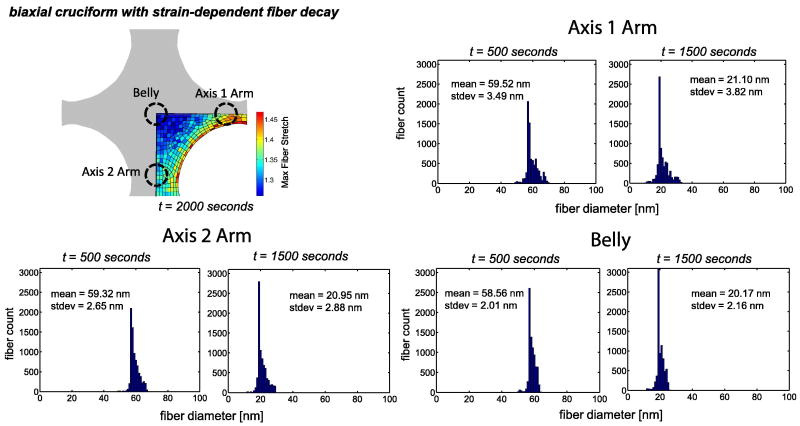
Three distinct regions of interest – the belly, the axis 1 arm, and the axis 2 arm – showed dissimilar fiber stretch ranges. These regions are marked in Fig. 8 alongside histograms of the fiber diameter in each region after 500 and 1500 seconds of enzymatic decay. Each histogram represents fibers from 8 individual RVEs from a region of interest. The standard deviation in the fiber diameter increased for each region from 500 to 1500 seconds of decay. The belly of the sample had the smallest spread in fiber diameter and the smallest average fiber diameter at both time points. The axis 1 arm, where the stress was largest, retained the largest fiber diameter over time and also had the widest spread in fiber diameter.
Fig 8.
Fiber diameter histograms for fibers sampled from elements in three distinct regions of the domain for the 30% equibiaxial stretch with strain-dependent decay case. Fibers were sampled at t = 500 and t = 1500 seconds. In each region, 8 individual RVEs were selected for analysis. The initial fiber diameter for the model was 100 nm.
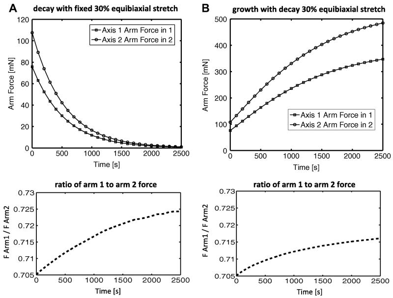
The forces in arm 1 (normal force acting along axis 1) and arm 2 (normal force acting along axis 2) diminished over time, as seen in Fig. 9. The steepest drop in force occurred at the initial onset of enzymatic decay, and the rate of decay decreased over time. The ratio between the two arm forces (force in arm 1 / force in arm 2) increased slightly over time and appeared to level off towards the end of the simulation.
Fig 9.
The axis 1 and axis 2 arm forces plotted for the (A) decay only and the (B) growth with decay 30% equibiaxial stretch cases. The ratio between arm forces (Farm1 / Farm2) is plotted for comparison.
3.3 Constant-strain equibiaxial extension with constant-rate growth and strain-dependent decay
As in the decay-only case, the constant-rate growth with decay case revealed a correlation between areas of greatest fiber stretch and areas with the greatest fiber diameter, as seen in Fig. 7b. The maximum and average fiber diameter per element, however, increased across all elements due to the action of the growth term in equation (2.5). The sample was held under a constant 30% equibiaxial extension, though the element-by-element maximum fiber stretches revealed non-uniformity in the local collagen network stretch. The forces in the arms increased over time due to growth, and, as in the degradation-only case, there was a slight shift toward equal forces as the system evolved (Fig. 9b).
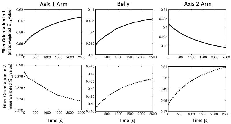
The mass weighted fiber orientation tensor, Ω, was calculated for 8 RVE collagen networks in each of the three regions of interest. Prior to loading and modeling growth and decay, networks in the sample had roughly an isotropic fiber orientation with Ω11 ≈ Ω22 ≈ Ω33 ≈ 0.33, with each normal component of the tensor yielding a relative strength of alignment in the corresponding axis. Immediately after loading but before any degradation / growth, the orientation shifted considerably due to fiber realignment (t = 0 points in Fig. 10). The diagonal elements of Ω were (0.56, 0.28, 0.16) for the narrow horizontal arm, (0.30, 0.48, 0.22) for the wide vertical arm, and (0.40, 0.42, 0.18) for the belly. To summarize, the fibers in the arms tended to align in the direction of pull, and the fibers in all sections tended to rotate into the plane of biaxial extension.
Fig 10.
Fiber orientation values (from the mass weighted orientation tensor) for three distinct regions of the cruciform in the 1 and 2 directions show localized changes in fiber alignment over time for the constant-rate growth and stain-dependent decay case for a constant 30% equibiaxial stretch. For comparison, a completely isotropic sample would have tensor orientation values of Ω11= 0.33 and Ω22 = 0.33 in the 1-2 plane.
Subsequent to the shift from isotropy after loading, the networks evolved over time from the action of constant-rate growth and enzymatic decay. The belly of the sample experienced the least change in fiber orientation, with its Ω11 and Ω22 values increasing approximately 2.5% and the network remaining nearly isotropic in the 1-2 plane. The axis 1 arm experienced an 8.4% increase in Ω11, shifting alignment into the direction of fixed extension for that arm via coupled growth and decay. The axis 2 arm experienced a similar but slightly less pronounced increase of 6.5% in its Ω22 component.
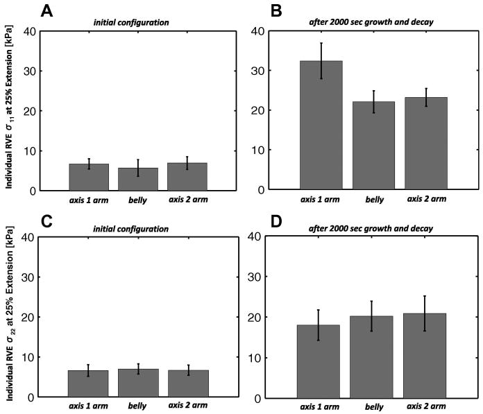
The relative change in RVE stiffness in the 1 and 2 directions is given in Fig. 11. The axis 1 arm stiffness in direction 1, calculated from 3 RVEs within the region subjected to a set of uniform uniaxial stretches, experienced a significant increase in the mean as compared with the other two regions (p<0.05). The mean stiffness in arm 2 increased in axis 2, but was not statistically significant (p =0.142) as compared to the mean stiffness in the other two regions.
Fig 11.
For the equibiaxial extension with constant-rate growth with enzymatic decay case (A) σ11 stress for n = 3 RVEs extended individually 25% in 1 from their undeformed configurations in the initial state and (B) after 2000 seconds of growth and decay. In (C) σ22 stress for n = 3 RVEs extended individually 25% in 2 from their undeformed configurations in the initial state and (D) after 2000 seconds of growth and decay. The RVEs were sampled from the areas of the arms and belly of the biaxial sample pictured in Fig. 7. Columns represent the mean value, and errorbars express the 95% confidence interval for each mean.
5 Discussion
As seen in Fig. 6b, the 0.4 N uniaxial hold simulation with decay had a diminished rate of fiber mass loss over time as compared with its 0.2 N counterpart. This is likely due to a subset of fibers within the 0.4 N hold that experienced greater strains than the 0.2 N case, and as a result, underwent diminished enzymatic degradation. In Fig. 6a, the greater sample strain over time for the 0.4 N case is evident. Qualitatively, the non-linear increase in strain over time for both the 0.2 N and 0.4 N holds and the greater strains generated with a larger magnitude fixed force resembles the experimental strain results from a set of creep experiments conducted recently by Zareian et al. with millimeter-scale collagenous corneal strip samples subjected to enzymatic decay (Zareian and Ruberti, 2010). This similarity is comforting, but the simplifications of the model must still be recognized. Immediately apparent is non-exponential nature of the decay in the experiments fit in Fig. 2. The actual degradation is slower at short time and then faster at long time, suggesting that a nonlinear equation for degradation could provide a better model. We would expect significant quantitative differences from a more accurate model but would not expect changes to the qualitative observations made here.
It also must be recognized that a real fiber will eventually fail. Shen et al. (2008) found that they could stretch collagen fibrils to 30-50% engineering strain without failure, but that yielding began at approximately 20% strain. Especially in the 0.4 N uniaxial extension case, the strains reached very large values (>100% engineering strain). The large strains are the result of a fixed load scenario where the grip-to-grip strain is increasing to maintain load in response to the dynamic degradation of fibers over time. One must assume that the sample would fail before being able to achieve some of our results. A model incorporating fiber failure as well as degradation and growth would be an important next step in analysis of these systems.
In the case of the constant strain biaxial enzymatic decay simulation, the results were consistent with remodeling serving as an adaptive process. Regions of higher stress (the arms, in particular the narrow arm) did not degrade as quickly as those of lower stress (the belly), and the relative stiffness of the regions under higher load increased vis-à-vis those under lower load. The belly region is important not only because its lower stresses provide for faster degradation, but also because the biaxial nature of the stress on the belly leads to roughly uniform stress within the network, so the spread in the fiber diameter was smaller. In the arms, fibers that were aligned in the stretch direction experienced significantly more stretch than those that were aligned transversely to the stretch direction, leading to greater variation in degradation rate and a greater spread in fiber diameter in Figure 8. The structural variations led to mechanical anisotropy of the sample, as shown in Fig. 11.
6 Conclusion
The model in the present study was able to successfully transfer a microscale fiber-based expression for strain-dependent decay and constant-rate growth into a deterministic macroscale outcome for an evolving tissue analog. Remodeling of collagenous tissue is an extremely complex process, including not only fiber degradation and growth but also mechanobiological effects on the cells in the tissue (e.g., changes in rate of MMP secretion or collagen deposition in response to different loads, Collins et al., 2005). The detailed interrelation between the fiber network and the cells that create and inhabit it, especially during development, growth, injury, and disease, remains an open question and important area for future study.
Acknowledgments
This work was supported by the National Institutes of Health (R01-EB005813) and by a National Science Foundation Research Fellowship. Computations were made possible by a resources grant from the Minnesota Supercomputing Institute.
Contributor Information
E.A. Sander, Email: sande399@umn.edu.
J.W. Ruberti, Email: j.ruberti@neu.edu.
V. H. Barocas, Email: baroc001@umn.edu.
References
- Adiguzel E, Ahmad PJ, Franco C, Bendeck MP. Collagens in the progression and complications of atherosclerosis. Vascular Medicine. 2009;14:73. doi: 10.1177/1358863X08094801. [DOI] [PubMed] [Google Scholar]
- Bhole AP, Flynn BP, Liles M, Saeidi N, Dimarzio CA, Ruberti JW. Mechanical strain enhances survivability of collagen micronetworks in the presence of collagenase: implications for load-bearing matrix growth and stability. Philosophical Transactions of the Royal Society A. 2009;367:3339. doi: 10.1098/rsta.2009.0093. [DOI] [PMC free article] [PubMed] [Google Scholar]
- Billiar KL, Sacks MS. Biaxial mechanical properties of the native and glutaraldehyde-treated aortic valve cusp: Part II—A structural constitutive model. Journal of Biomechanical Engineering. 2000;122:327. doi: 10.1115/1.1287158. [DOI] [PubMed] [Google Scholar]
- Chandran PL, Barocas VH. Deterministic material-based averaging theory model of collagen gel micromechanics. Journal of Biomechanical Engineering. 2007;129:137. doi: 10.1115/1.2472369. [DOI] [PubMed] [Google Scholar]
- Chandran PL, Barocas VH. Affine versus non-affine fibril kinematics in collagen networks: theoretical studies of network behavior. Journal of Biomechanical Engineering. 2006;128:259. doi: 10.1115/1.2165699. [DOI] [PubMed] [Google Scholar]
- Chandran PL, Barocas VH. Microstructural mechanics of collagen gels in confined compression: poroelasticity, viscoelasticity, and collapse. Journal of Biomechanical Engineering. 2004;126:152. doi: 10.1115/1.1688774. [DOI] [PubMed] [Google Scholar]
- Collins JM, Ramamoorthy K, Silveira AD, Patston P, Mao JJ. Expression of matrix metalloproteinase genes in the rat intramembranous bone during postnatal growth and upon mechanical stresses. Journal of Biomechanics. 2005;38:485. doi: 10.1016/j.jbiomech.2004.04.018. [DOI] [PubMed] [Google Scholar]
- Cumming B, McElwain D, Upton Z. A mathematical model of wound healing and subsequent scarring. Journal of the Royal Society Interface. 2010;7:19. doi: 10.1098/rsif.2008.0536. [DOI] [PMC free article] [PubMed] [Google Scholar]
- Driessen NJB, Cox MAJ, Bouten CVC, Baaijens FPT. Remodeling of the angular collagen fiber distribution in cardiovascular tissues. Biomechanics and Modeling in Mechanobiology. 2008;7:93. doi: 10.1007/s10237-007-0078-x. [DOI] [PMC free article] [PubMed] [Google Scholar]
- Flynn BP, Bhole AP, Saeidi N, Liles M, DiMarzio CA, Ruberti JW, Orgel JPRO. Mechanical Strain Stabilizes Reconstituted Collagen Fibrils against Enzymatic Degradation by Mammalian Collagenase Matrix Metalloproteinase 8 (MMP-8) PloS One. 2010;5:e12337. doi: 10.1371/journal.pone.0012337. [DOI] [PMC free article] [PubMed] [Google Scholar]
- Galis ZS, Khatri JJ. Matrix metalloproteinases in vascular remodeling and atherogenesis: the good, the bad, and the ugly. Circulation Research. 2002;90:251. [PubMed] [Google Scholar]
- Holmes JW, Borg TK, Covell JW. Structure and mechanics of healing myocardial infarcts. Annual Review of Biomedical Engineering. 2005;7:223. doi: 10.1146/annurev.bioeng.7.060804.100453. [DOI] [PubMed] [Google Scholar]
- Jhun CS, Evans MC, Barocas VH, Tranquillo RT. Planar Biaxial Mechanical Behavior of Bioartificial Tissues Possessing Prescribed Fiber Alignment. Journal of Biomechanical Engineering. 2009;131:081006. doi: 10.1115/1.3148194. [DOI] [PMC free article] [PubMed] [Google Scholar]
- Kuhl E, Garikipati K, Arruda EM, Grosh K. Remodeling of biological tissue: Mechanically induced reorientation of a transversely isotropic chain network. Journal of the Mechanics and Physics of Solids. 2005;53:1552. [Google Scholar]
- Lake SP, Barocas VH. Characterization of mechanical and structural contribution of non-fibrillar extracellular matrix in uniaxial tension: a collagen-agarose co-gel model. Annals of Biomedical Engineering. 2011;39:1891. doi: 10.1007/s10439-011-0298-1. [DOI] [PMC free article] [PubMed] [Google Scholar]
- Lauer-Fields JL, Juska D, Fields GB. Matrix metalloproteinases and collagen catabolism. Peptide Science. 2002;66:19. doi: 10.1002/bip.10201. [DOI] [PubMed] [Google Scholar]
- Luo XJ, Stylianopoulos T, Barocas VH, Shephard MS. Multiscale computation for bioartificial soft tissues with complex geometries. Engineering with Computers. 2009;25:87. [Google Scholar]
- Madden JW, Peacock EE., Jr Studies on the biology of collagen during wound healing. 3. Dynamic metabolism of scar collagen and remodeling of dermal wounds. Annals of Surgery. 1971;174:511. doi: 10.1097/00000658-197109000-00017. [DOI] [PMC free article] [PubMed] [Google Scholar]
- Nerurkar NL, Ramasubramanian A, Taber LA. Morphogenetic adaptation of the looping embryonic heart to altered mechanical loads. Developmental Dynamics. 2006;235:1822. doi: 10.1002/dvdy.20813. [DOI] [PubMed] [Google Scholar]
- Pardo A, Selman M. MMP-1: the elder of the family. The International Journal of Biochemistry & Cell Biology. 2005;37:283. doi: 10.1016/j.biocel.2004.06.017. [DOI] [PubMed] [Google Scholar]
- Ramasubramanian A, Taber LA. Computational modeling of morphogenesis regulated by mechanical feedback. Biomechanics and Modeling in Mechanobiology. 2008;7:77. doi: 10.1007/s10237-007-0077-y. [DOI] [PMC free article] [PubMed] [Google Scholar]
- Robinson PS, Johnson SL, Evans MC, Barocas VH, Tranquillo RT. Functional tissue-engineered valves from cell-remodeled fibrin with commissural alignment of cell-produced collagen. Tissue Engineering Part A. 2008;14A:83. doi: 10.1089/ten.a.2007.0148. [DOI] [PubMed] [Google Scholar]
- Ruberti JW, Hallab NJ. Strain-controlled enzymatic cleavage of collagen in loaded matrix. Biochemical and Biophysical Research Communications. 2005;336:483. doi: 10.1016/j.bbrc.2005.08.128. [DOI] [PubMed] [Google Scholar]
- Sacks MS, Schoen FJ, Mayer JE., Jr Bioengineering challenges for heart valve tissue engineering. Biomedical Engineering. 2009;11:289. doi: 10.1146/annurev-bioeng-061008-124903. [DOI] [PubMed] [Google Scholar]
- Sander EA, Barocas VH. Biomimetic collagen tissues: collagenous tissue engineering and other applications. Collagen: Structure and Mechanics, Springer. 2008:475–504. [Google Scholar]
- Sander EA, Stylianopoulos T, Tranquillo RT, Barocas VH. Image-based biomechanics of collagen-based tissue equivalents: Multiscale models compared to fiber alignment predicted by polarimetric imaging. IEEE Engineering in Medicine and Biology Magazine: The Quarterly Magazine of the Engineering in Medicine & Biology Society. 2009a;28:10. doi: 10.1109/MEMB.2009.932486. [DOI] [PMC free article] [PubMed] [Google Scholar]
- Sander EA, Stylianopoulos T, Tranquillo RT, Barocas VH. Image-based multiscale modeling predicts tissue-level and network-level fiber reorganization in stretched cell-compacted collagen gels. Proceedings of the National Academy of Sciences. 2009b;106:17675. doi: 10.1073/pnas.0903716106. [DOI] [PMC free article] [PubMed] [Google Scholar]
- Sander E, Barocas VH. Comparison of 2D fiber network orientation measurement methods. Journal of Biomedical Materials Research Part A. 2009c;88A:322. doi: 10.1002/jbm.a.31847. [DOI] [PubMed] [Google Scholar]
- Sander EA, Stein AM, Swickrath MJ, Barocas VH. Out of Many, One: Modeling Schemes for Biopolymer and Biofibril Networks. Challenges and Advances in Computational Chemistry and Physics. 2010;9:557. [Google Scholar]
- Sastry A, Cheng X, Wang C. Mechanics of stochastic fibrous networks. Journal of Thermoplastic Composite Materials. 1998;3:288. [Google Scholar]
- Shen ZL, Dodge MR, Kahn H, Ballarini R, Eppell SJ. Stress-strain experiments on individual collagen fibrils. Biophysical Journal. 2008;95:3956. doi: 10.1529/biophysj.107.124602. [DOI] [PMC free article] [PubMed] [Google Scholar]
- Stein AM, Vader DA, Weitz DA, Sander LM. The micromechanics of three-dimensional collagen-I gels. Complexity. 2010 doi: 10.1002/cplx.20332. [DOI] [Google Scholar]
- Stylianopoulos T, Barocas VH. Multiscale, structure-based modeling for the elastic mechanical behavior of arterial walls. Journal of Biomechanical Engineering. 2007a;129:611. doi: 10.1115/1.2746387. [DOI] [PubMed] [Google Scholar]
- Stylianopoulos T, Barocas VH. Volume-averaging theory for the study of the mechanics of collagen networks. Computer Methods in Applied Mechanics and Engineering. 2007b;196:2981. [Google Scholar]
- Taber LA, Humphrey JD. Stress-modulated growth, residual stress, and vascular heterogeneity. Journal of Biomechanical Engineering. 2001;123:528. doi: 10.1115/1.1412451. [DOI] [PubMed] [Google Scholar]
- Varner VD, Voronov DA, Taber LA. Mechanics of head fold formation: investigating tissue-level forces during early development. Development. 2010;137:3801. doi: 10.1242/dev.054387. [DOI] [PMC free article] [PubMed] [Google Scholar]
- Weber KT. Extracellular matrix remodeling in heart failure: a role for de novo angiotensin II generation. Circulation. 1997;96:4065. doi: 10.1161/01.cir.96.11.4065. [DOI] [PubMed] [Google Scholar]
- Zareian R, Church KP, Saeidi N, Flynn BP, Beale JW, Ruberti JW. Probing collagen/enzyme mechanochemistry in native tissue with dynamic, enzyme-induced creep. Langmuir. 2010;26:9917. doi: 10.1021/la100384e. [DOI] [PMC free article] [PubMed] [Google Scholar]


