Abstract
Background
Assessment of patient function after TKA often focuses on implant alignment and daily activity capabilities, but the functional results and kinematics of the TKA are not easily predicted by some of these parameters during surgery.
Questions/purposes
We asked whether differences in implant alignment in the transverse plane may affect fluorokinematics and be one of the many variables that help explain the discrepancies in fluorokinematic results.
Methods
We utilized a computer model (LifeMOD™/KneeSIM; LifeModeler, Inc, San Clemente, CA, USA) to show variability in polyethylene contact patterns. We imported components of a cruciate-retaining TKA into the model and subjected the systems to a simulated lunge. We modeled five different combinations of implant positioning in the transverse plane of both the femoral and tibial components in internal or external rotation and compared the resulting changes in joint rotations and displacements of these five variations to those for published fluorokinematic observations using the same modeled lunge-type maneuver for five patients.
Results
We observed variations in AP translation of the lateral and medial femoral condyles resembling several of those in the literature for individual patients with the same cruciate-retaining knee implant. The largest AP translational changes were seen with the tibia internally rotated 5°. Using the five different implant transverse plane alignment scenarios resulted in a coefficient of determination of 0.6 for the linear regression when compared to five subjects from a published fluorokinematic study.
Conclusions
Variations in implant positioning may be responsible for variations in fluorokinematics reported for individual subjects with the same implant design.
Clinical Relevance
If validated computer modeling can aid surgeons to predict the effects of individual implant alignment variations in TKA kinematics, a more personalized approach to implant positioning during TKA can be implemented.
Introduction
Failure of TKA can occur for a variety of reasons. Some TKA failures are due to implant-directed causes, while others are directly related to surgical technique [1–5, 7, 17, 18, 20–22]. Sharkey et al. [18] reported more than ½ of TKA failures were due to instability, malalignment, malposition, or failure of fixation, all factors that are potentially avoidable with meticulous surgical technique. Given these findings, it is incumbent upon the surgeon to study or know the impact of surgical technique-related issues on TKA function to allow for better decision making during the procedure.
Previous investigations, both clinical and in the laboratory, demonstrate surgical technique influences on TKA kinematics and patient-perceived outcomes [1–5, 7, 13, 15, 17, 18, 20–22]. Insall et al. [7] found a direct correlation between femoral condylar liftoff and malrotation of the femoral component from the transepicondylar axis. Barrack et al. [2] reported the presence and severity of femoral component internal rotation correlated with patellofemoral complications. In a cadaveric study, Werner et al. [21] found varus/valgus malalignment altered tibiofemoral load distribution. Furthermore, in a retrieval analysis, Wasielewski et al. [20] identified specific wear patterns contributing to implant failure and their relationship to technical aspects in TKA. It is clear many variables play a role in patient-perceived TKA function. Once these variables are determined, it is logical to investigate their effects on one another and how a surgeon may be able to aid his/her surgical decision making based on these findings.
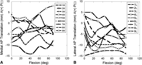
Many of the functional assessment tools we currently utilize for TKA are not sensitive enough to detect many of the variables related to surgical technique and TKA discussed above. The Knee Society Function Scores [12], while a good tool for an overall measure of how well a patient returns to activities of daily living, is not a good tool for differentiating surgical technique parameters, such as deviation from the mechanical axis or rotational alignment of implant, during surgery. Recently, investigators have utilized fluoroscopic analysis to study in vivo TKA kinematics to further describe motion and the functional parameters of TKA postoperatively [9–11, 14, 19]. While these studies provide insight into TKA kinematics, they also reveal wide variations from patient to patient [9–11, 14, 19]. For example, Li et al. [11] found AP translations in the medial and lateral compartments varied considerably between subjects (Fig. 1). It is unclear what accounts for these variations. Possible explanations include variations in how each implant was aligned to the patient’s own anatomic parameters during the operation and variation in each individual’s muscle strength and loading patterns during the lunge maneuver utilized in the study.
Fig. 1A–B.
Replots of Figure E-1 from the electronic appendix to Li et al. [11] show contact positions (AP translations in the [A] medial and [B] lateral compartments) of nine individual patients with a NexGen® CR total knee implant performing a lunge maneuver under fluoroscopic surveillance. The curves for the contact positions over 90° of flexion have different shapes for each subject, varying in magnitude of displacements, direction, and changes in direction.
We therefore asked whether (1) changes in femoral and/or tibial component rotation in the transverse plane alter TKA clinical displacements, (2) many of the variations seen on fluorokinematic analyses may be due to a combination of variations in surgical technique, and (3) the computer model results with varying implant positioning are comparable to previous reports of TKA fluorokinematic data, which will aid in supporting our model results.
Materials and Methods
We created a computer model of a reverse-engineered TKA so that variations in implant alignment in the transverse plane could be modeled and investigated. The model was subjected to a described lunge-type maneuver from a previous fluorokinematic study so that the results of changing implant alignment in the transverse plane could be compared to the published patient data to answer the question as to whether surgical variations may account for the variability reported in fluorokinematic studies.
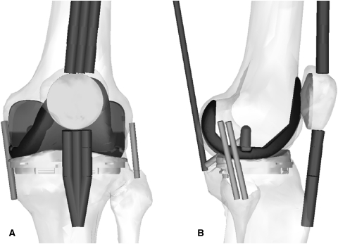
We used a virtual knee simulator (LifeMOD™/KneeSIM; LifeModeler, Inc, San Clemente, CA, USA), based on multibody dynamics, to simulate a lunge in a manner similar to the in vivo lunge maneuver reported in fluoroscopic studies of TKA kinematics [9–12, 19]. The model included tibiofemoral and patellofemoral contact, passive soft tissue (medial and lateral collateral ligaments, PCL, and capsular tissues), and active muscle elements (quadriceps and hamstrings). The soft tissue elements remained in the same position and orientation for all models tested in the study. We imported parasolid models of a fixed-bearing, cruciate-retaining (CR), total knee prosthesis (NexGen®; Zimmer, Inc, Warsaw, IN, USA) into a model of a left knee (Fig. 2) and subjected them to one 60-second cycle of a simulated lunge (0°–120°–0° flexion). For each of the modeled implant positions, we measured the AP positions from the recorded femoral lateral and medial condyles to the lowest points on the tibial tray (the same measure used in fluoroscopy studies [9–11, 14]). We positioned both the femoral and tibial components in the following combinations of 5° internal or external rotation and analyzed the resulting kinematics: (1) femoral component neutral with tibia component in neutral alignment; (2) tibial component 5° internal, femoral component 5° internal; (3) tibial component 5° internal, femoral component 5° external; (4) tibial component 5° external, femoral component 5° internal; and (5) tibial component 5° external, femoral component 5° external.
Fig. 2A–B.
Drawings show (A) AP and (B) lateral views of the knee model and the NexGen® CR implant in neutral position and show the positions of the extensor mechanism and soft tissue components in the model.
We placed the tibial component with 0° of posterior slope as defined from the neutral transverse plane and placed the neutral alignment according to the epicondylar axis and the medial 1/3 of the tibia tubercle where the femoral and tibial polyethylene tray obtained the highest amount of conformity. Neutral rotational alignment was then defined as zero from the sagittal plane.
To simulate a lunge maneuver where the subject progressively unloads the knee in deeper flexion (by shifting weight of arm support), we applied a constant vertical force of 463 N to the hip until 80° of flexion, after which we linearly reduced it to 0 N at 120°. A closed-loop controller monitored knee flexion and compared it to the prescribed input, and quadriceps and hamstrings loads were adjusted to obtain the prescribed flexion angle at each time point. The ankle was free to AP translation and abduction-adduction and was given internal-external rotational stiffness and damping properties derived from the literature (torsional ankle stiffness of 10 pound inch/° and damping of 1 pound inch second/°) [8]. Flexion-extension was prevented at the ankle. We simulated one cycle of flexion-extension over a total duration of 60 seconds to perform the lunge.
We compared the data from Li et al. [11] to the five simulated models with varying implant orientations by averaging the model results at every 15° of flexion and comparing model mean results to mean results of all nine patients evaluated. In addition, we compared the five simulated cases to five of the nine patients from the study whose clinical rotation magnitude and direction at full extension, as assessed from the starting relative AP fluoroscopic contact positions, were most similar to the direction and magnitude of malalignment in the model.
We performed a linear regression analysis of the relative medial and lateral fluoroscopic contact positions of Li et al. [11] on the relative calculated contact positions for the five model implant orientations.
Results
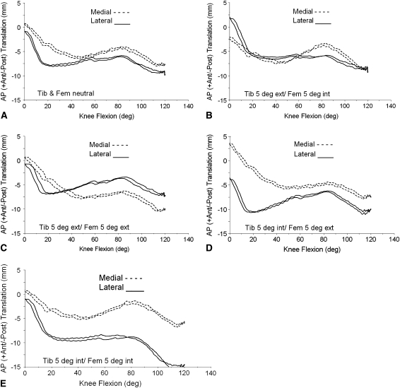
Differences in clinical displacements were seen for each different modeled tibial and femoral alignment in the transverse plane (rotation) (Fig. 3). For displacements, the model resulted in forward sliding of the medial femoral condylar contact starting around 40° of flexion no matter what combination of the positioning we modeled in the transverse plane. The amount of forward sliding was the highest on the medial side when we internally rotated the femoral component with internal or external placement of the tibial component (4.5 mm) and the lowest when we externally rotated the femoral and tibial implants (1.25 mm).
Fig. 3A–E.
Graphs show calculated AP contact positions using contact reporting methods similar to those employed in fluoroscopic studies for femoral and tibial components placed in a variety of internal-external rotational positions, including (A) femoral component neutral with tibia component in neutral alignment (Tib & Fem neutral); (B) tibial component 5° external, femoral component 5° internal (Tib 5 deg ext, Fem 5 deg int); (C) tibial component 5° external, femoral component 5° external (Tib 5 deg ext, Fem 5 deg ext); (D) tibial component 5° internal, femoral component 5° external (Tib 5 deg int, Fem 5 deg ext); and (E) tibial component 5° internal, femoral component 5° internal (Tib 5 deg int, Fem 5 deg int). Ant = anterior; post = posterior.
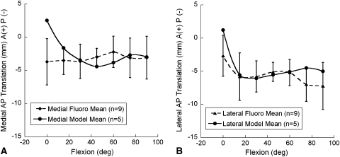
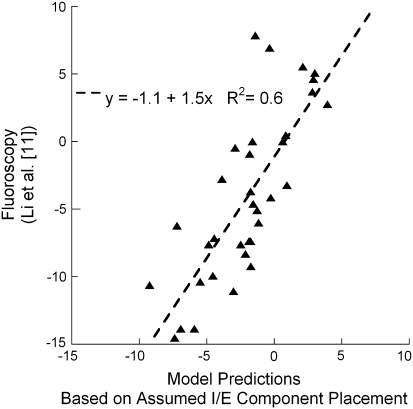
When we averaged the five model results, the medial and lateral compartment contact points throughout the lunge maneuver resulted in means that fell within one SD of the means of the nine subjects of Li et al. [11] for all angles except at full extension (Fig. 4). This could possibly be due to the full extension angle in the fluoroscopic study not being exactly at 0° of flexion. Because no translation had yet taken place at full extension, the difference could also be partially attributed to differences in the magnitude of initial implant rotational alignment in the study of Li et al. [11] as compared to that assumed in the model. A third possible explanation might be that the subjects were not fully weightbearing at full extension and the implants had not yet settled into an equilibrium position that would be achieved under full weightbearing. The model applies a full 473-N load during an equilibrium step preceding the lunge simulation, which allows the components to settle. The fact that modeling just five variations in rotational alignment produced means that fell within one SD of the larger number of nine subjects in the fluoroscopic study suggests rotational alignment is partly responsible for all nine of the subjects and not just the five subjects chosen for direct comparison on the basis of similarity to the five model cases in the shape of the contact translation versus flexion curves and the initial relative contact positions. A regression analysis of the model with five variations in positioning to five of the nine subjects from the study of Li et al. [11] indicated 60% of the variance in the fluoroscopic data was explained by the computer models (p < 0.0001) with 5° variations in component internal-external rotational positioning (Fig. 5). Thus, a direct measure by regression analysis of the ability of model variations in implant rotational position to predict the motion of the tibiofemoral fluoroscopic contacts suggests more than ½ of the variability is accounted for by this variation alone.
Fig. 4A–B.
Graphs show tibiofemoral contact locations (mean, SD) for the (A) lateral and (B) medial compartments of the knee during a lunge maneuver at 15° increments of flexion from full extension to 90° of knee flexion. Means for the five models with variations in implant orientation in the present study are plotted. Means for nine patients were recalculated from the fluoroscopic work of Li et al. [11] and are plotted along with one-SD bars for comparison. The five model means fall within one SD of the nine fluoroscopic subject means, except for the stationary position at full extension. A = anterior; P = posterior.
Fig. 5.
A graph shows relative AP contact positions (mm) (lateral with respect to medial side) of five subjects during lunge knee bending in a fluoroscopic study [11] as predicted by model simulations of a lunge with the same implant positioned in five combinations of rotational placement. The coefficient of determination (p < 0.001) suggests 60% of the variance may be explained by variations in implant rotational positioning in the transverse plane. + = anterior; − = posterior; I/E = internal/external.
Discussion
TKA outcomes have focused on alignment of implants and daily activity capabilities, but the kinematics of the TKA is not easily predicted during surgery. We therefore asked whether (1) changes in femoral and/or tibial component rotation in the transverse plane alter TKA clinical displacements, (2) many of the variations seen on fluorokinematic analyses may be due to a combination of variations in surgical technique as modeled by implant rotational placement in the transverse plane, and (3) the computer model results with varying implant positioning under one set of muscle forces and ligament stiffness values are comparable to previous reports of TKA fluorokinematic data, which will aid in supporting our model results.
Limitations of the study include the following. First, it was subject to assumptions and variables common to many computational models: boundary conditions and muscle forces were assumed, the entire lower extremity was not modeled, and ankle and hip reactions and motions were assumed. Second, the fluoroscopic lunge maneuver that was modeled might not have been accurate according to how each patient performed the lunge maneuver clinically or in the compared clinical study [11]. Variations observed in the fluorokinematic studies might have occurred because of the technique utilized to perform the lunge or squat maneuver. If one patient holds on to a rail for support while another does not, this could result in substantial variations in the contact patterns and kinematics of the knee. We assumed each patient performed the maneuver without an aid such as a handrail and was able to fully perform the lunge in a fluent fashion, which we believed was appropriate given no data from the comparative study otherwise [11]. Third, in addition to the need to standardize methods for performing fluoroscopic lunge maneuvers, some sort of supporting model is necessary before the computational models could be tested for intraoperative use. Justification of the computational model would include comparative studies of measured clinical rotations and displacements in the operating room and those of functional activities in a gait analysis laboratory to ensure the robust nature and sensitivity of the model. Passive open-chain types of movement in the operating room may not be able to predict these functional differences; comparative studies are needed of knee kinematics in an anesthetized patient versus a patient actively performing a lunge maneuver. All of these issues must be determined before the realization of utilizing this kind of modeling to personalize the surgical approach can be initiated.
We first attempted to see whether any variation in clinical displacements occurred with differences in tibial and femoral implant alignment in the transverse plane. The computational model resulted in differences in AP translation, which were largest with the tibial baseplate in 5° of internal rotation. The differences in condylar contact with small variation in implant rotational alignment in the transverse plane would suggest surgical technique does contribute to variations reported in fluorokinematic studies. A linear regression fit of the relative contact positions of the lateral and medial side of five fluoroscopic patients of Li et al. [11] with our computer model results of five different implant positions resulted in a coefficient of determination of 0.6. This suggests variations in implant position could explain as much as 60% of the observed variability in fluoroscopic kinematic surveillance studies. With only one variable changed for surgical technique the model compared favorably with the experimental results, suggesting the variation in surgical parameters may be one of the determining factors of larger variations reported in fluorokinematic studies [9–11, 14, 19]. The targets that surgeons utilize for a TKA are often listed as a neutral mechanical axis and transverse plane positioning of the femoral component along the AP axis or perpendicular to the epicondylar axis, with equal soft tissue balancing. Although these parameters are often taught, they are not normal parameters seen in lower-extremity anatomy [17]. Recently, a study by Parratte et al. [15] reported an alignment outside 3° of the normal mechanical axis does not successfully predict a poor-functioning TKA in a series of patients. While mechanical alignment is important, there are multiple surgically controllable variables involved in producing a successful TKA, including coronal, transverse, and sagittal plane soft tissue stability [1, 4, 6, 17, 21]. Also, in some varus knees, there are individuals who have a large adductor moment, which predicts failures in patients receiving high tibial osteotomy [16], but there is no similar study showing where muscle forces are mapped out that predicts a higher failure rate in TKA. However, there may be patients with strong tensor fascia latae muscles that can counter medial compartment forces in a varus knee after TKA surgery. This fact also brings to light that in our study muscle force distribution and hip joint forces were assumed and were not varied while the transverse rotational positioning of the implants were changed. One can argue varying the muscle forces that effect internal (pes anserine tendon forces) or external (tensor fascia latae, biceps femoris) rotation of the tibia may give further variations in the resulting kinematics. This study focused on the effects of surgical positioning and therefore did not include these other variations. Many other variables can be explored to define the robustness of the model before implementation for any clinical determinations during surgery.
Other implications for the outcome of this study are that variations in transverse plane positioning seem to affect the medial and lateral compartment contact points in different ways. A more favorable contact profile with less forward sliding is evident with external rotation of the femoral component. However, there is a compensatory increase in the amount of forward sliding in the lateral compartment. Internal rotation of the femoral component tends to increase the amount of forward sliding in the medial compartment, with the highest seen with combined internal rotation of the tibial component.
The computer modeling approach utilized in this study could be useful in the operating room if supported by other clinically relevant loading schemes. If anatomic parameters could be registered during TKA, it may be possible to predict the small variations in implant positioning, along with a patient’s individual soft tissue laxity and anatomy, which could allow a surgeon to make better decisions about implant positioning in the operating room on a personalized patient basis. The reader must realize many other variables, such as muscle forces and quality of ligament support and stiffness, may play a further role in determining the variations that may occur from differing surgical techniques before the robustness of the computer model is appropriate for clinical use.
Footnotes
One or more of the authors (WMM, JLW) has received funding from Corin Ltd (Cirencester, UK) and Aesculap, Inc (Center Valley, PA, USA). WMM has a consultancy and royalty agreement with Aesculap, Inc. One author (JLW) has received software licenses from LifeModeler, Inc (San Clemente, CA, USA).
Each author certifies that his or her institution approved or waived approval for the human protocol for this investigation and that all investigations were conducted in conformity with ethical principles of research.
The work was performed at InMotion Orthopaedic Research Center and the University of Memphis.
References
- 1.Aglietti P, Sensi L, Cuomo P, Ciardullo A. Rotational position of femoral and tibial components in TKA using the femoral transepicondylar axis. Clin Orthop Relat Res. 2008;466:2751–2755. doi: 10.1007/s11999-008-0452-8. [DOI] [PMC free article] [PubMed] [Google Scholar]
- 2.Barrack RL, Schrader T, Bertot AJ, Wolfe MW, Myers L. Component rotation and anterior knee pain after total knee arthroplasty. Clin Orthop Relat Res. 2001;392:46–55. doi: 10.1097/00003086-200111000-00006. [DOI] [PubMed] [Google Scholar]
- 3.Bourne RB, Chesworth BM, Davis AM, Mahomed NN, Charron KD. Patient satisfaction after total knee arthroplasty: who is satisfied and who is not? Clin Orthop Relat Res. 2010;468:57–63. doi: 10.1007/s11999-009-1119-9. [DOI] [PMC free article] [PubMed] [Google Scholar]
- 4.Cobb JP, Dixon H, Dandachli W, Iranpour F. The anatomical tibial axis: reliable rotational orientation in knee replacement. J Bone Joint Surg Br. 2008;90:1032–1038. doi: 10.2106/JBJS.H.00606. [DOI] [PubMed] [Google Scholar]
- 5.Gandhi R, Tso P, Davis A, Mahomed NN. Outcomes of total joint arthroplasty in academic versus community hospitals. Can J Surg. 2009;52:413–416. [PMC free article] [PubMed] [Google Scholar]
- 6.Graw BP, Harris AH, Tripuraneni KR, Giori NJ. Rotational references for total knee arthroplasty tibial components change with level of resection. Clin Orthop Relat Res. 2010;468:2734–2738. doi: 10.1007/s11999-010-1330-8. [DOI] [PMC free article] [PubMed] [Google Scholar]
- 7.Insall JN, Scuderi GR, Komistek RD, Math K, Dennis DA, Anderson DT. Correlation between condylar lift-off and femoral component alignment. Clin Orthop Relat Res. 2002;403:143–152. doi: 10.1097/00003086-200210000-00022. [DOI] [PubMed] [Google Scholar]
- 8.Johnson C, Hull ML. Parameter identification of the human lower limb under dynamic, transient torsional loading. J Biomech. 1988;21:401–415. doi: 10.1016/0021-9290(88)90146-7. [DOI] [PubMed] [Google Scholar]
- 9.Kitagawa A, Tsumura N, Chin T, Gamada K, Banks SA, Kurosaka M. In vivo comparison of knee kinematics before and after high-flexion posterior cruciate-retaining total knee arthroplasty. J Arthroplasty. 2010;25:964–969. doi: 10.1016/j.arth.2009.07.008. [DOI] [PubMed] [Google Scholar]
- 10.Komistek RD, Mahfouz MR, Bertin KC, Rosenberg A, Kennedy W. In vivo determination of total knee arthroplasty kinematics: a multicenter analysis of an asymmetrical posterior cruciate retaining total knee arthroplasty. J Arthroplasty. 2008;23:41–50. doi: 10.1016/j.arth.2007.01.016. [DOI] [PubMed] [Google Scholar]
- 11.Li G, Suggs J, Hanson G, Durbhakula S, Johnson T, Freiberg A. Three-dimensional tibiofemoral articular contact kinematics of a cruciate-retaining total knee arthroplasty. J Bone Joint Surg Am. 2006;88:395–402. doi: 10.2106/JBJS.D.03028. [DOI] [PubMed] [Google Scholar]
- 12.Liow RY, Walker K, Wajid MA, Bedi G, Lennox CM. The reliability of the American Knee Society Score. Acta Orthop Scand. 2000;71:603–608. doi: 10.1080/000164700317362244. [DOI] [PubMed] [Google Scholar]
- 13.Mannion AF, Kämpfen S, Munzinger U, Kramers-de Quervain I. The role of patient expectations in predicting outcome after total knee arthroplasty. Arthritis Res Ther. 2009;11:R139. doi: 10.1186/ar2811. [DOI] [PMC free article] [PubMed] [Google Scholar]
- 14.Mikashima Y, Tomatsu T, Horikoshi M, Nakatani T, Saito S, Momohara S, Banks SA. In vivo deep-flexion kinematics in patients with posterior-cruciate retaining and anterior-cruciate substituting total knee arthroplasty. Clin Biomech (Bristol, Avon) 2010;25:83–87. doi: 10.1016/j.clinbiomech.2009.09.009. [DOI] [PubMed] [Google Scholar]
- 15.Parratte S, Pagnano MW, Trousdale RT, Berry DJ. Effect of postoperative mechanical axis alignment on the fifteen-year survival of modern, cemented total knee replacements. J Bone Joint Surg Am. 2010;92:2143–2149. doi: 10.2106/JBJS.I.01398. [DOI] [PubMed] [Google Scholar]
- 16.Prodromos CC, Andriacchi TP, Galante JO. A relationship between gait and clinical changes following high tibial osteotomy. J Bone Joint Surg Am. 1985;67:1188–1194. [PubMed] [Google Scholar]
- 17.Scuderi GR, Komistek RD, Dennis DA, Insall JN. The impact of femoral component rotational alignment on condylar lift-off. Clin Orthop Relat Res. 2003;410:148–154. doi: 10.1097/01.blo.0000063603.67412.ca. [DOI] [PubMed] [Google Scholar]
- 18.Sharkey PF, Hozack WJ, Rothman RH, Shastri S, Jacoby SM. Insall Award paper. Why are total knee arthroplasties failing today? Clin Orthop Relat Res. 2002;404:7–13. doi: 10.1097/00003086-200211000-00003. [DOI] [PubMed] [Google Scholar]
- 19.Sharma A, Komistek RD, Scuderi GR, Cates HE., Jr High-flexion TKA designs: what are their in vivo contact mechanics? Clin Orthop Relat Res. 2007;464:117–126. doi: 10.1097/BLO.0b013e318157e478. [DOI] [PubMed] [Google Scholar]
- 20.Wasielewski RC, Galante JO, Leighty RM, Natarajan RN, Rosenberg AG. Wear patterns on retrieved polyethylene tibial inserts and their relationship to technical considerations during total knee arthroplasty. Clin Orthop Relat Res. 1994;299:31–43. [PubMed] [Google Scholar]
- 21.Werner FW, Ayers DC, Maletsky LP, Rullkoetter PJ. The effect of valgus/varus malalignment on load distribution in total knee replacements. J Biomech. 2005;38:349–355. doi: 10.1016/j.jbiomech.2004.02.024. [DOI] [PubMed] [Google Scholar]
- 22.Zihlmann MS, Stacoff A, Romero J, Quervain IK, Stüssi E. Biomechanical background and clinical observations of rotational malalignment in TKA: literature review and consequences. Clin Biomech (Bristol, Avon) 2005;20:661–668. doi: 10.1016/j.clinbiomech.2005.03.014. [DOI] [PubMed] [Google Scholar]


