Abstract
Five functional silanes, 3-aminopropyltriethoxysilane (APTES), 3-aminopropyltrimethoxysilane (APTMS), N-(2-aminoethyl)-3-aminopropyltriethoxysilane (AEAPTES), and N-(2-aminoethyl)-3-aminopropyltrimethoxysilane (AEAPTMS), and N-(6-aminohexyl)aminomethyltriethoxysilane (AHAMTES) were assessed for the preparation of hydrolytically stable amine-functionalized silica substrates. These can be categorized into three groups (G1, G2, and G3) based on the intra-molecular coordinating ability of the amine functionality to the silicon center. Silanizations were carried out in anhydrous toluene as well as in the vapor phase at elevated temperatures. Aminosilane-derived layers prepared in solution are multilayers in nature and those produced in the vapor phase have monolayer characteristics. In general, vapor-phase reactions are much less sensitive to variations in humidity and reagent purity, are more practical than solution-phase method, and generate more reproducible results. Intra-molecular catalysis by the amine functionality is found to be important for both silanizaton and hydrolysis. The primary amine group in the G1 silanes (APTES and APTMS) can readily catalyze siloxane bond formation and hydrolysis to render their silane layers unstable toward hydrolysis. The amine functionality in the G3 silane (AHAMTES) is incapable of intra-molecular catalysis of silanization so that stable siloxane bonds between the silane molecules and surface silanols do not form easily. The secondary amine group in the G2 silanes (AEAPTES and AEAPTMS), on the other hand, can catalyze siloxane bond formation, but the intra-molecular catalysis of bond detachment is sterically hindered. The G2 silanes are the best candidates for preparing stable amine-functionalized surfaces. Between the two G2 aminosilanes, AEAPTES results in more reproducible silane layers than AEAPTMS in the vapor phase due to its lower sensitivity to water content in the reaction systems.
Introduction
Aminosilanes are widely used coupling agents for silica-based materials because of their bifunctional nature. Nucleophilicity of –NH2 groups in aminosilanes, for example, is taken advantage of in promoting adhesion in glass-resin composites.1–3 In aqueous media of low to medium pH values, –NH3+ groups promote the attachment of negatively charged species, such as DNA4,5 and nanoparticles.6,7 Whether the applications of aminosilanes are industrial, biological, or environmental, the hydrolytic stability of the aminosilane-derived layers is critical to the success of the derivatization reactions and the long-term stability of the conjugated systems.
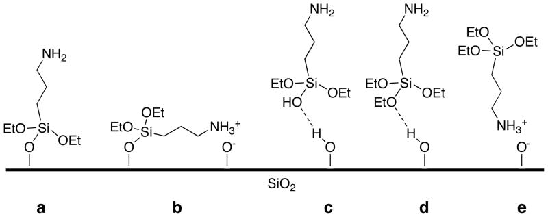
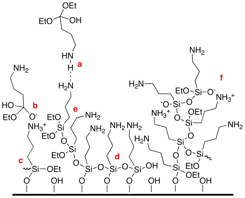
3-aminopropyltriethoxysilane (APTES) is the most commonly used aminosilane. The popularity of this aminosilane is coupled with complexities in its usage. One of the main issues lies in the fact that there are many possible ways for it to interact with surface silanol/silanolate groups, via hydrogen bonds, electrostatic attractions, and siloxane bonds (Figure 1).8 Some of the conformations have been implicated in low silane grafting density (Figure 1b)9 and others result in weakly attached silane molecules (Figures 1c–e). Secondly, APTES has three ethoxy groups per molecule and is capable of polymerizing in the presence of water, which can give rise to a number of possible surface structures: covalent attachment, two-dimensional self-assembly (horizontal polymerization), and multilayers (vertical polymerization).10 Thirdly, excess water results in not only uncontrolled polymerization of silane molecules on surface, but also formation of oligomers and polymers of silanes in bulk/solution,11 which can also react with and attach to the surface. The extents of alkoxy hydrolysis and amine protonation in the silane layers also depend on the amount of water present.12 Additionally, the amine functionality can inter- and intra-molecularly catalyze silane attachment and formation of oligomers and polymers of silanes.9 Some typical structural features in an APTES-derived layer are shown in Figure 2. The physiosorbed, hydrogen bonded (a) or electrostatically attached (b) silane molecules are not stable. Among the covalently attached silanes, some have reacted with only surface silanol groups (c) and others have bonded with neighboring silane molecules in horizontal (d) and/or vertical directions (e). Some of the silanes shown are attached to the surface in oligomeric form (f), which introduces additional disorder in the silane layer. As a result of the complexities discussed above, the nature of bonding at the interface and within the aminosilane layer is not clear.13 Questions include: What is the relative distribution of covalent bonds, hydrogen bonds, and electrostatic interactions? What is the extent of crosslinking among the silane molecules? What is the chemical nature of the amine functionality? What is the density of the available amine functionality? These uncertainties can greatly affect the stability and the effectiveness of further conjugations using the aminosilane layers.
Figure 1.
Different types of interactions between APTES molecules and silicon dioxide substrates: (a) a covalently attached APTES molecule with its amine group extending away from the interface, (b) a covalently attached APTES molecule with its amine group interacting with a surface silanol group, and (c)–(e) weakly bounded APTES molecules.
Figure 2.
An APTES-derived layer with structural irregularities: individual silane molecules can be incorporated into the layer via a) hydrogen bonding, b) electrostatic attraction, c) covalent bonding with the substrate, d) horizontal and e) vertical polymerization with neighboring silanes; f) oligomeric/polymeric silanes can also react/interact with functionalities present at the interface.
Significant effort has been spent on optimizing silanization conditions in solution – type of solvent,14 amount of water present,15 silane concentration,15 temperature,8,16,17 time,8,15,17 and drying/curing condition13–15,18,19 – for the preparation of aminosilane layers with structural regularities. There are fewer reports on silanization in the vapor phase.9,20–25 Vapor-phase modification offers obvious advantages in eliminating solvent use and not having substrates in direct contact with silane solutions in terms of avoiding excess water9 and direct depositions of silane oligomers/polymers onto substrates. Vapor-phase depositions generally result in smooth silane monolayers,20–23 which are attractive for many applications. There is uncertainty, however, with regard to whether silane molecules are attached to silica substrates via siloxane bonds or hydrogen bonds. Soaking/rinsing in water subsequent to vapor deposition was found to promote siloxane bond formation.26
Among the published studies, very few focused on the effect of structural features of the aminosilanes on silane layer quality and stability. In one of the vapor-phase deposition studies, 3-aminopropyldiisopropylethoxysilane monolayers were reported to be more hydrolytically stable than APTES and 3-aminoproyldimethylethoxysilane monolayers on silicon wafers. It was attributed to the hydrophobicity and the steric hindrance provided by the isopropyl groups.22 We recently reported that aminosilane-derived layers prepared with 3-aminopropylalkoxysilanes suffer extensive loss upon exposure to water at moderate temperature.8 This is likely caused by siloxane bond hydrolysis catalyzed by the amine functionality via the formation of a stable five-membered cyclic intermediate. Enhanced stability was found in layers prepared from N-(6-aminohexyl)aminomethyltriethoxysilane (AHAMTES) in anhydrous toluene. The amine functionality in AHAMTES is less likely to participate in intra-molecularly catalyzed siloxane bond hydrolysis due to the much longer alkyl linker separating the silicon atom and the amine group(s). The report established the importance of choosing appropriate aminosilanes – that are incapable of intra-molecularly catalyzing hydrolysis – in order to prepare hydrolytically stable aminosilane layers in anhydrous solutions.
In this study, solution- and vapor-phase silanizations were carried out using five representative and commercially available aminosilanes with the general formulas, NH2(CH2)nSi(OR)3 and NH2(CH2)mNH(CH2)nSi(OR)3, where n and m are positive integers and R represents either a methyl or an ethyl group. Silanization protocols and silane structural requirements for the preparation of reproducible, homogenous, and hydrolytically stable aminosilane layers were established.
Experimental
General
Silicon wafers (100 orientation, P/B doped, resistivity 1–10 Ω-cm, thickness 475–575 μm) were purchased from International Wafer Service. Silane coupling agents, 3-aminopropyltriethoxysilane (APTES, 99.7%), 3-aminopropyltrimethoxysilane (APTMS, 98.5%), N-(6-aminohexyl)aminomethyltriethoxysilane (AHAMTES, 99.7%), N-(2-aminoethyl)-3-aminopropyltriethoxysilane (AEAPTES, 97.4%), and N-(2-aminoethyl)-3-aminopropyltrimethoxysilane (AEAPTMS, 98.3%), were purchased from Gelest. The purity information was provided by the manufacturer. The silanes were stored in Schlenk flasks under nitrogen and used without further distillation. House-purified water (reverse osmosis) was purified in a Millipore Milli-Q Biocell System (Millipore) that involved reverse osmosis, ion exchange, and filtration (18.2 MΩ-cm). Other reagents were used as received from Fisher Scientific. Solution-phase silanization was carried out in anhydrous toluene that was dried and deoxygenated using a Pure Solv 400-6 solvent purification system (Innovative Technology). All glassware was cleaned in a base bath (potassium hydroxide in isopropyl alcohol and water), rinsed with distilled water (3×), and stored in a clean oven at 110 °C until use.
Instrumentation
Thickness measurements were carried out with an LSE Stokes Ellipsometer (Gaertner Scientific). The light source is a He-Ne laser with wavelength of 632.8 nm and a 70° angle of incidence (from the normal to the plane). Thickness was calculated using the following parameters: air, no = 1; silicon oxide and silane-derived layers, n1 = 1.46;10,14,20 silicon substrate, ns = 3.85 and ks = −0.02. Measurement error is within 1 Å as specified by the manufacturer. The standard deviation of reported thickness values – averages of four measurements on each of at least four samples prepared in at least three separate batches – is within the instrument error unless it is specified otherwise. Contact angle was measured with a Rame-Hart telescopic goniometer with a Gilmont syringe and a 24-gauge flat-tipped needle. The probe fluid was Milli-Q water. Dynamic advancing (θA) and receding (θR) angles were recorded while the probe fluid was added to and withdrawn from the drop, respectively. The standard deviation of reported contact angle values – averages of three measurements on each of at least three samples prepared in separate batches – is less than 2°. Atomic force microscopy images were obtained with a Veeco Metrology Dimension 3100 atomic force microscope (AFM) with a silicon tip operated in tapping mode. Roughness of surface features was determined using the Nanoscope software. Surface atomic compositions were analyzed using a Quantum 2000 Scanning ESCA Microprobe (Physical Electronics) at 15° and 45° take-off angles.
Clean silicon wafers
Silicon wafers (1.2 × 1.5 cm) were cleaned by submerging in a freshly prepared piranha solution containing 7 parts concentrated sulfuric acid and 3 parts 30% hydrogen peroxide for 45 min (caution: piranha solution reacts violently with organic matter). After being removed from the solution, wafers were rinsed with copious amounts of Milli-Q water and dried in a clean oven at 110 °C for 30 min.
Silanization
Freshly cleaned wafers were immediately placed in a custom-designed glass holder, which was introduced to a Schlenk flask. The flask was closed and purged extensively with nitrogen. All of the reagents were subsequently added to the flask under nitrogen. Solution phase reaction was carried out in 25 mL of anhydrous toluene containing 0.5 mL of silane at 70 °C for a desired amount of time. For the vapor-phase silanization, there was no contact between the samples and the 0.5 mL aliquot of aminosilane; reaction was carried out at either 70 °C or 90 °C for a desired amount of time. After silanization, the wafers were rinsed individually with toluene (2×), ethanol (2×), and water (2×), and dried in an oven at 110 °C for 15 min. Thickness and contact angle measurements were carried out immediately upon sample cooling.
Hydrolytic stability of silanized layers
Freshly silanized samples were submerged in Milli-Q water at 40 °C for up to 48 h. Samples were then rinsed in Milli-Q water and dried in an oven at 110 °C for 15 min before characterization.
Results and Discussion
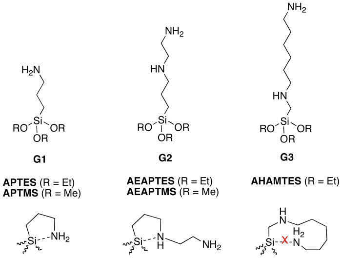
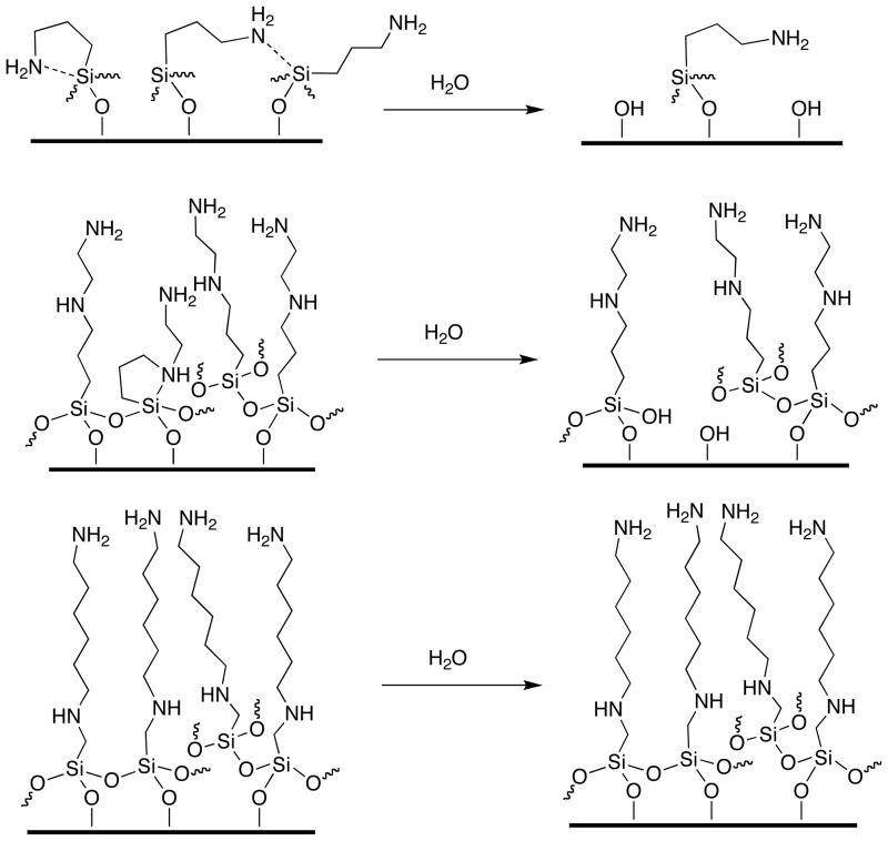
All of the commercially available aminosilanes were surveyed and categorized into three groups (Figure 3) based on the ability of the amine functionality for intra-molecular catalysis. Group I (G1) reagents have a primary amine group in the propyl (γ) position. The amine group is capable of catalyzing the formation and hydrolysis of siloxane bonds both intra- and inter-molecularly. Intra-molecular catalysis is achieved via the formation of stable five-membered cyclic intermediates.9 APTES and APTMS were chosen as representatives of the G1 aminosilanes. Group II (G2) reagents have a secondary amine group in the propyl position. Similar to the G1 reagents, they are capable of intra- and inter-molecular catalysis, however, are likely impeded by steric effects. AEAPTES and AEAPTMS were chosen to represent the G2 aminosilanes. Group III (G3) reagents do not have an amine group in the propyl (or butyl) position. The amine functionality in G3 reagents is only capable of inter-molecular catalysis of siloxane bond formation and hydrolysis. AHAMTES is the only G3 silane chosen since its trimethoxysilane counterpart is not commercially available.
Figure 3.
Aminosilanes are categorized into three groups based on the ability of the amine functionality in intra-molecular catalysis; representatives for each group are shown.
Trialkoxy aminosilanes were chosen over their monoalkoxy and dialkoxy counterparts because of their potential in forming the most number of siloxane bonds with silica substrates and neighboring silane molecules. In each of the three groups, a triethoxy aminosilane and its trimethoxy counterpart (if available) are included due to the difference in hydrolysis rates between the two types of alkoxy groups. In the presence of water (e.g. from silicon wafer surface, glassware surface, environment, and solvent), hydrolysis of alkoxy groups precedes siloxane bond formation.27 The faster hydrolysis rate of methoxy groups can result in more siloxane bonds in the silane layer and/or higher sensitivity of the layer structure to the amount of water in the system. The outcome in the comparison between triethoxy and trimethoxy aminosilanes will affect the reagent choice in the preparation of reproducible and stable silane layers.
Based on their molecular structures, the G1 reagents have a chain length of ~5 Å, the G2 reagents have a chain length of ~8 Å, and the G3 reagent has a chain length of ~10 Å, assuming that each bond contributes to ~1 Å to overall chain length. These values are estimates of the thicknesses of the corresponding closely packed monolayers on silicon wafers. Thicknesses and morphologies of the different aminosilane layers prepared in two reaction media, anhydrous toluene and vapor phase, before and after hydrolysis were characterized and compared.
Solution-phase silanization
The general consensus for preparing smooth aminosilane layers includes the following: 1) an anhydrous solvent, such as toluene, with an adventitious amount of water is critical in controlling the extent of polymerization of aminosilanes at the interface and in solution;15 2) low silane concentration discourages the formation of oligomers and polymers in solution;15 3) moderate reaction temperature, such as 70 °C, can disrupt hydrogen bonds and reduce the number of weakly bonded silane molecules in silane layers;8,16 4) after silanization, rinsing substrates with toluene, ethanol, and water facilitates the displacement of weakly bonded silane molecules and the hydrolysis of residual alkoxy groups in silane layers;14,26 5) drying and curing at elevated temperature, e.g. 110 °C, promotes condensation of hydrogen-bonded silanols to form siloxane bonds and converts ammonium ions to the neutral and more reactive amine groups.13–15,18,19 These guidelines facilitated the selections of reaction parameters for the preparation of aminosilane-derived layers in anhydrous toluene using the five silanes from the three groups.
Despite our efforts in painstakingly purging the reaction systems with nitrogen and using anhydrous toluene, ambient humidity varying from ~20% in winter to ~60% in summer has a large impact on silane layer thickness and variability. Humidity levels were recorded on the days when experiments were performed. For example, the APTMS layer thicknesses were 15 ± 5 Å and 36 ± 5 Å when the humidity levels were 19% and 37%, respectively, and the AEAPTES-derived layers were 92 ± 11 Å at 39% and 355 ± 100 Å at 59% humidity levels; both types of layers were prepared at 24 h silanization time. When there was more moisture in the environment, silane layers were thicker and more variable, presumably due to the increased extent of oligomerization/polymerization in solution and vertical polymerization on surface. Reported averages and standard deviations in this study are based on at least three separate data sets obtained on days with different recorded humidity levels.
Another major issue that we encountered in solution-phase silanization was the effect of silane purity on layer thickness, variability, and stability. In order to compare silane layer thickness and stability among the five aminosilanes, both silanization and subsequent hydrolysis were carried out for 24 h. As we have established in our previous study, thicker silane layers can be prepared at longer reaction time in solution;8 a fixed reaction time allows us to compare silanization rates of different types of aminosilanes. It was further demonstrated that most of the hydrolytic degradation at 40 °C occurs within 24 h,8 therefore, 24 h is an appropriate time to compare the hydrolytic stability of the different types of silane layers. We emphasize that “hydrolytic stability” does not refer to thermodynamic stability, but to the kinetic stability of the silane layers, which is assessed by the residual layer thicknesses after a certain amount of hydrolysis time in this study. Table 1 provides reagent purity information and characterization of different silane layers before and after hydrolysis. All aminosilanes except AEAPTES result in similar layer thicknesses, from 21 to 25 Å. The AEAPTES-derived layers, on the other hand, are almost 300 Å thick with a standard deviation of ~200 Å. Furthermore, the thick AEAPTES layers are not as hydrolytically stable – after soaking in water for 24 h, only 4 Å-thick layers remained on the surface, the lowest among all the silane layers. The AFM images of the AEAPTES and AHAMTES layers before and after hydrolysis are shown in Figure 4. The AHAMTES layer as prepared is not very smooth, which is consistent with its thickness corresponding to that of a multilayer. After hydrolysis, the layer decreased in thickness to a value that is slightly higher than that of a monolayer. Its surface features, however, resemble those prior to hydrolysis. These observations are in agreement with our previous report.8 On the other hand, the AEAPTES layer as prepared is much rougher and degrades to a smooth, featureless surface corresponding to a monolayer with a low silane density after hydrolysis. The much thicker and rougher AEAPTES layers likely result from the attachment of oligomeric and polymeric forms of silanes (Figure 2f). The few anchoring sites to the surface and the disordered structures render the attached oligomers and polymers prone to hydrolytic detachment. AEAPTES has the lowest purity among the five aminosilanes. Impurities in an aminosilane may exist in the form of oligomers and polymers, resulting from reaction between silane molecules and a trace amount of water during reagent manufacturing and/or storage. Distillation was not performed in this study due to its impracticality in most of the aminosilane applications. AEAPTES is excluded from the rest of the discussion of solution-phase silanization.
Table 1.
Ellipsometric thickness and contact angle (θA/θR) data for five aminosilane layers, prepared in anhydrous toluene at 70 °C for 24 h, before and after exposure to water for 24 h at 40 °C.
| Purity (%) | As prepared | After hydrolysis | ||||
|---|---|---|---|---|---|---|
| Thickness (Å) | Contact angle (°) | Thickness (Å) | Contact angle (°) | |||
| G1 | APTES | 99.7 | 23 ± 4 | 32/16 | 8 ± 2 | 24/14 |
| APTMS | 98.5 | 25 ± 12 | 44/17 | 10 ± 4 | 26/13 | |
|
| ||||||
| G2 | AEAPTES | 97.4 | 282 ± 207 | 35/12 | 4 ± 1 | 30/14 |
| AEAPTMS | 98.3 | 24 ± 4 | 54/19 | 19 ± 6 | 46/14 | |
|
| ||||||
| G3 | AHAMTES | 99.7 | 21 ± 2 | 48/18 | 14 ± 4 | 49/18 |
Figure 4.
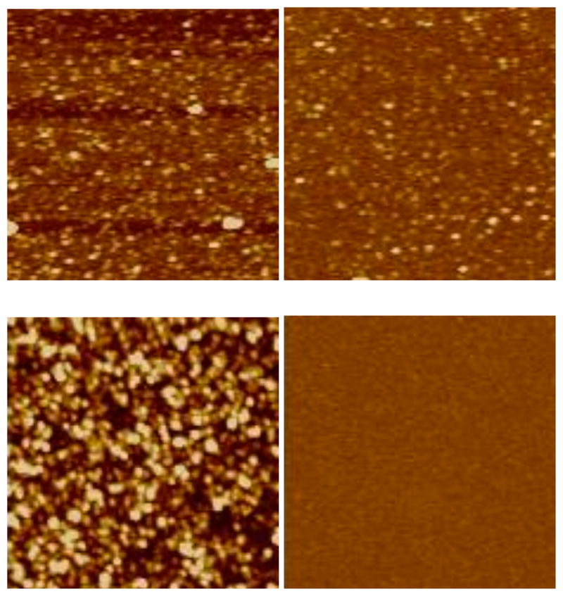
AFM images (1.25 × 1.25 μm, height scale is 10 nm) of AHAMTES- (top left) and AEAPTES-derived (bottom left) layers prepared in toluene at 70 °C for 24 h and the corresponding samples (right) after immersion in water at 40 °C for 24 h.
Effect of silane structural features on rates of silanization and hydrolysis is only qualitatively assessed here due to the compounding influence of humidity and silane purity. The four aminosilanes produced silane layers with comparable thicknesses at 24 h reaction time. Relative to their respective monolayer thickness, they all produced multilayers: the G1 reagents generated 5 (± 2) layers, the G2 reagent produced 3 (± 1) layers, and the G3 reagent resulted in 2 (± 1) layers. Although there is a decreasing trend in layer thickness from the G1, the G2, to the G3 reagents, the standard deviations are too large for it to be conclusive. Reaction kinetics (not shown) also did not show appreciable differences among the three groups of aminosilanes. The three types of reagents have different abilities in intra-molecular catalysis but similar ability in inter-molecular catalysis. The latter appears to contribute significantly to the overall rate of silanization based on the similar reaction kinetics of different silanes. Relative hydrolytic stability of the different types of silane layers is also compared. All of the remaining silane layers after 24 h hydrolysis are thicker than their respective monolayers. Based on the percent of reduction in layer thickness and the extent of decrease in water contact angles of silane-modified surfaces after hydrolysis (Table 1), the G2 and G3 silanes outperform the G1 silanes. The differences in their structural features contribute to the slight differences in the hydrolytic stability as illustrated in Figure 5. Hydrolysis of the attached G1 silane molecules can be catalyzed inter- as well as intra-molecularly. The G2 silane layers can also be catalytically degraded but with more steric hinderance due to the longer chain length. On the other hand, hydrolysis of the G3 layer cannot be intra-molecularly catalyzed. Figure 5 also indicates that increasing silane grafting density and structural regularity would impede the penetration of water molecules into the silane layer and sterically retard inter- and intra-molecularly catalyzed hydrolysis. The G1 silanes yielded surprisingly more robust layers than those reported in our previous study.8 Exhaustive removal of water from reaction systems in the current study presumably resulted in more densely grafted and thus more hydrolytically stable silane layers.
Figure 5.
Hydrolysis of three types of silane layers.
Silanization carried out in solution is significantly influenced by ambient humidity and silane purity (the presence of oligomers and polymers). Although addressing these issues is possible in practice, it requires skills and is laborious. Data presented here (and elsewhere) are associated with significant standard deviation, and are thus difficult to reproduce.
Vapor-phase silanization
To minimize the effects of humidity and silane purity on the reproducibility of silane layer preparation, the vapor-phase approach was evaluated. Anhydrous toluene contains a trace amount of water and its nonpolar nature renders water in the system to converge on the hydrophilic substrates. Removing solvent from the reaction system should result in a smaller (and more controllable) amount of water on the substrate surface.9 Furthermore, oligomeric and polymeric silanes have negligible vapor pressure at moderate reaction temperatures and thus, do not participate in surface reactions. Based on these rationales, the vapor-phase approach should circumvent the shortcomings of silanization in solution.
Silanization reaction using the G3 reagent, AHAMTES, was carried out in the vapor phase first. Very thin monolayers were obtained at various reaction temperatures and times. For example, ~2 Å-thick layers were obtained at 90 °C after 48 h and degraded completely upon soaking in water for 24 h. Interestingly, ~20 Å-thick layers deposited on silicon wafers prior to the rinsing procedure. This indicates that the vapor pressure of AHAMTES at 90 °C is sufficient to allow a significant number of silane molecules to interact with the substrates. Most of the silane molecules, however, are likely weakly bonded (Figure 1) and are removed from the surface during the rinsing process. This result is very different from that in solution. Presumably, the higher molecular mobility in solution can disrupt hydrogen bonds more effectively. Additionally, the concentration of silane molecules in the vapor phase is lower, thus, inter-molecularly catalyzed silanization is not likely to occur. Furthermore, AHAMTES is unlikely to engage in intra-molecular catalysis. Formation of siloxane bonds competes with other types of weaker interactions between the silane molecules and the substrate. The uncatalyzed silanization of AHAMTES in the vapor phase presumably contributes to the formation of silane layers consisting primarily of weakly bonded silane molecules. After rinsing and curing steps, low-density AHAMTES monolayers are thus produced.
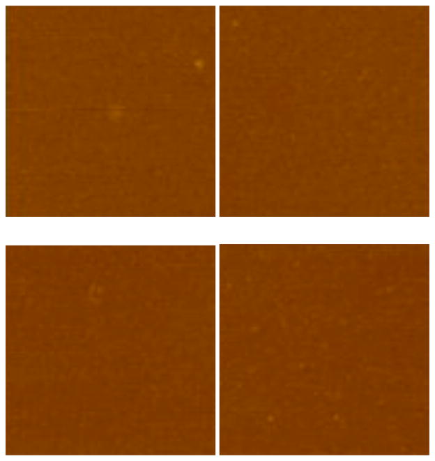
The G1 and G2 reagents were evaluated next using the vapor-phase method. Table 2 shows the thicknesses of four types of silane layers prepared at 70 °C after 24 h and the residual thicknesses after 24 h hydrolysis. Compared to that of AHAMTES, the thicknesses of these silane layers are appreciable, corresponding to those of monolayers to multilayers. This indicates that intra-molecularly catalyzed silanization of G1 and G2 reagents are important in rendering facile siloxane bond formation at the solid-vapor interfaces. It appears that silane purity does not have the same effect on layer thickness and variability in vapor-phase silanization as in solution. In fact, AEAPTES, which has the lowest purity, produced layers with the lowest thickness. It is also noteworthy that the trimethoxysilanes generated thicker layers with larger standard deviations than the corresponding triethoxysilanes. The faster hydrolysis rate of methoxy groups likely causes the extent of reactions to be more susceptible to variations in the amount of water on substrate surfaces. Triethoxysilanes appear to be better candidates in generating more reproducible silane layers. 6 Å-thick APTES layers and 5 Å-thick AEAPTES layers were obtained. Considering that their closely packed monolayers should be ~5 Å and ~8 Å, respectively, the AEAPTES layers prepared at 70 °C are of low density. Due to its larger molecular size, AEAPTES has a lower vapor pressure than APTES. Reaction temperature was subsequently raised to 90 °C to increase silane vapor pressures as well as molecular dynamics at the solid-vapor interfaces. Table 3 provides thickness and water contact angle data of the APTES and AEAPTES layers obtained at 24 h and 48 h reaction times, before and after 24 h hydrolysis. The APTES layers prepared at 24 h and 48 h had indistinguishable thicknesses of ~5 Å and degraded to ~3 Å corresponding to low-density monolayers. On the other hand, the AEAPTES layers prepared at 48 h were thicker and more stable than those obtained at 24 h. AEAPTES layers obtained at 90 °C and 48 h were ~11 Å and decreased in thickness slightly after hydrolysis to ~8 Å, which is comparable to the estimated thickness of its closely packed monolayers. The AFM images of the APTES and AEAPTES layers before and after hydrolysis (Figure 6) confirm the preparation of monolayers. Their surfaces are extremely smooth, which is in significant contrast to the ones prepared in solution (Figure 4). Although the AFM images and water contact angles of the APTES and AEAPTES layers are indistinguishable before and after hydrolysis, thickness data do indicate that the AEAPTES layers are more stable. In a related study, stable AEAPTMS layers were prepared using vapor deposition at 160 °C for 12 h.20 The SEM images of the silane layers appear rough, which could be caused by the gold coating and/or the poor quality of the images. It was also reported that vapor deposition of AEAPTMS at room temperature produced hydrolytically unstable layers.20 In another related study, N-(6-aminohexyl)-3-aminopropyltrimethoxysilane was vapor deposited onto silicon wafers at 100 °C for up to 5 h.21 The silane layers have monolayer characteristics and are stable after sonication in aqueous media for 40 min.21 These findings corroborate our conclusion that stable aminosilane monolayers can be prepared in the vapor phase at elevated temperature using the G2 reagents.
Table 2.
Ellipsometric thickness data of the G1 and G2 aminosilane layers, prepared at 70 °C for 24 h in the vapor phase, before and after exposure to water for 24 h at 40 °C.
| Initial (Å) | After hydrolysis (Å) | ||
|---|---|---|---|
| G1 | APTES | 6 ± 1 | 3 ± 1 |
| APTMS | 13 ± 9 | 9 ± 5 | |
|
| |||
| G2 | AEAPTES | 5 ± 1 | 2 ± 1 |
| AEAPTMS | 19 ± 17 | 4 ± 1 | |
Table 3.
Ellipsometric thickness and contact angle (θA/θR) data of the APTES and AEAPTES layers, prepared at 90 °C for 24 h or 48 h in the vapor phase, before and after exposure to water for 24 h at 40 °C.
| Initial | After hydrolysis | ||||
|---|---|---|---|---|---|
| Thickness (Å) | Contact angle (°) | Thickness (Å) | Contact angle (°) | ||
| APTES | 24 h | 5 ± 1 | 50/23 | 3 ± 1 | 34/15 |
| 48 h | 5 ± 1 | 51/23 | 3 ± 1 | 37/15 | |
|
| |||||
| AEAPTES | 24 h | 6 ± 1 | 50/24 | 3 ± 1 | 35/17 |
| 48 h | 11 ± 2 | 51/22 | 8 ± 1 | 38/16 | |
Figure 6.
AFM images (1.25 × 1.25 μm, height scale is 10 nm) of the APTES- (top left) and AEAPTES-derived (bottom left) layers prepared at 90 °C for 48 h in the vapor phase and the corresponding samples (right) after immersion in water at 40 °C for 24 h.
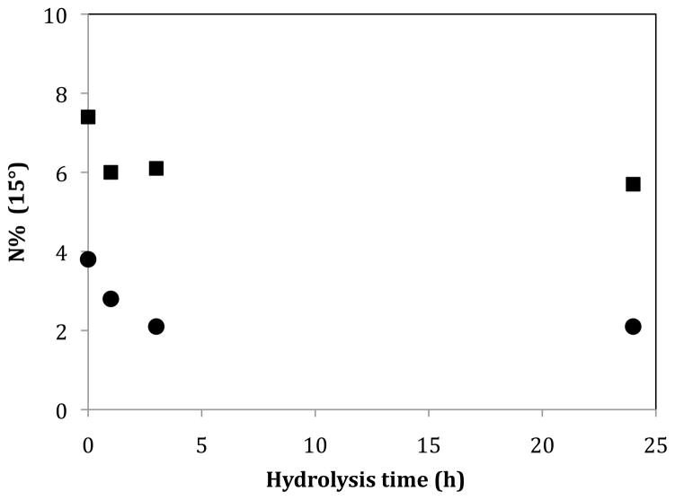
Quantitative analysis of the degradation process was also carried out using x-ray photoelectron spectroscopy (XPS). Nitrogen contents on the APTES- and AEAPTES-modified samples were monitored as a function of hydrolysis time at both 15° and 45° take-off angles. Since the silane monolayers are thin, the more surface-sensitive data obtained at 15° take-off angle are presented here although the data at 45° take-off angle follow the same trend. It appears that the AEAPTES layers initially have about twice as much nitrogen as the APTES layers, which is consistent with their molecular compositions and monolayer characteristic. Upon hydrolysis, the nitrogen content on the AEAPTES-derived layers decreased from 7.4% to ~6%, with no further loss after 1 h. The most loss on the APTES-derived layers occurred in the initial 3 h, from 3.8% to 2.1% nitrogen content. Both thickness and XPS data point to less hydrolytic loss of the AEAPTES layers. The difference in hydrolytic stability between the G1 and G2 aminosilane layers is likely due to the more sterically hindered intra-molecularly catalyzed hydrolysis for the G2 aminosilanes, as shown in Figure 5. The hydrolytic stability of the AEAPTES-derived layers implies stable siloxane bond formation between the silane molecules and the surface silanols under the preparation conditions used in this study. The nitrogen peak from XPS appears as a singlet at 399 eV (not shown) indicating that nitrogen is primarily present as –NH2/–NH– since the protonated state would have a higher binding energy.15 Our finding is consistent with literature reports that sample curing at elevated temperatures converts protonated amines to neutral amines.13, 15 The neutral state of the amine functionality in aminosilane-derived layers provides versatility in their applications.
Conclusions
This is a comprehensive evaluation of commercially available aminosilanes for the preparation of reproducible, homogeneous, and hydrolytically stable silane layers on silicon wafers using solution-phase as well as vapor-phase silanization methods. Five representative silanes were chosen and categorized into three groups based on the ability of the amine functionality in intra-molecularly catalyzed silanization and hydrolysis. In a G1 silane molecule, the primary amine group in the propyl (γ) position can coordinate to the silicon atom forming a stable five-membered cyclic intermediate for intra-molecular catalysis. A similar cyclic intermediate can form via the coordination of a secondary amine group to the silicon atom in a G2 silane. However, intra-molecular catalysis is unlikely in a G3 silane due to the much longer alkyl linker separating the silicon atom and the amine groups. Different types of silane layers were prepared from toluene as well as in the vapor phase under anhydrous conditions and the reaction conditions were optimized in both reaction media. The following guidelines are concluded from this study and are provided to researchers who are interested in preparing aminosilane-dervied layers on silica substrates.
Aminosilane multilayers are typically produced from anhydrous toluene at moderate temperature. The reproducibility, however, is significantly affected by many factors, such as silane purity and humidity.
Smooth silane monolayers can be prepared using vapor-phase silanization at elevated temperature. The vapor-phase method is less sensitive to variations in the reaction systems than solution-phase silanization.
APTES and APTMS (G1 reagents) yield the least hydrolytically stable silane layers due to the facile intra-molecularly catalyzed hydrolysis.
AHAMTES (a G3 reagent) cannot intra-molecularly catalyze silanization so that they are unable to generate high-density silane layers in the vapor phase. If high-purity reagents are obtained and strict anhydrous conditions are accomplished, they are reasonable candidates for solution-phase silanization in that silane monolayers remain on substrates upon extended soaking in water.
Silane layers of AEAPTES and AEAPTMS (G2 reagents) can be prepared readily using both solution- and vapor-phase silanization and they are relatively stable due to steric hindrance of intra-molecularly catalyzed hydrolysis.
Triethoxysilanes produce silane layers with low variability due to their lower sensitivity to water than the trimethoxysilanes.
In summary, the vapor-phase approach eliminates the need for silane purification and generates more reproducible results compared to silanizations carried out in solution. Among the three groups of aminosilanes, AEAPTES, a triethoxysilane in G2, is able to generate the most stable monolayers in the vapor phase due to its unique structural features.
Figure 7.
XPS nitrogen contents obtained at 15° take-off angle of the APTES (●) and AEAPTES (■) layers prepared at 90 °C for 48 h in the vapor phase as a function of hydrolysis time at 40 °C.
Acknowledgments
Financial support was provided by the National Institutes of Health (2R15EB139-2) and the National Science Foundation (DMR 1005324). The use of the NSF-MRSEC central facilities at the University of Massachusetts is also acknowledged.
References
- 1.Plueddemann EW. Silane Coupling Agents. 2. Pleum; New York: 1991. [Google Scholar]
- 2.Zisman WA. Ind Eng Chem Prod Res Dev. 1969;8:98–111. [Google Scholar]
- 3.Ishida H. Polym Comp. 1984;5:101–123. [Google Scholar]
- 4.Kneuer C, Sameti M, Haltner EG, Schiestel T, Schirra H, Schmidt H, Lehr CM. Int J Pharm. 2000;196:257–261. doi: 10.1016/s0378-5173(99)00435-4. [DOI] [PubMed] [Google Scholar]
- 5.Roy I, Ohulchanskyy TY, Bharali DJ, Pudavar HE, Mistretta RA, Kaur N, Prasad PN. Proc Natl Acad Sci USA. 2005;102:279–284. doi: 10.1073/pnas.0408039101. [DOI] [PMC free article] [PubMed] [Google Scholar]
- 6.Chen CF, Tzeng SD, Lin MH, Gwo S. Langmuir. 2006;22:7819–7824. doi: 10.1021/la060656r. [DOI] [PubMed] [Google Scholar]
- 7.Enders D, Nagao T, Pucci A, Nakayama T. Surf Sci. 2006;600:L71–L75. [Google Scholar]
- 8.Smith EA, Chen W. Langmuir. 2008;24:12405–12409. doi: 10.1021/la802234x. [DOI] [PMC free article] [PubMed] [Google Scholar]
- 9.Kanan SM, Tze WTY, Tripp CP. Langmuir. 2002;18:6623–6627. [Google Scholar]
- 10.Fadeev AY, McCarthy TJ. Langmuir. 2000;16:7268–7274. [Google Scholar]
- 11.Unger KK, Kinkel JN. J Chromatogr. 1984;316:193–200. doi: 10.1016/s0021-9673(01)89040-3. [DOI] [PubMed] [Google Scholar]
- 12.Caravajal GS, Leyden DE, Quinting GR, Maciel GE. Anal Chem. 1988;60:1776–1786. [Google Scholar]
- 13.Kim J, Holinga GJ, Somorjai GA. Langmuir. 2011;27:5171–5175. doi: 10.1021/la2007205. [DOI] [PubMed] [Google Scholar]
- 14.Vandenberg ET, Bertilsson L, Liedberg B, Uvdal K, Erlandsson R, Elwing H, Lundstron I. J Coll Int Sci. 1991;147:103–118. [Google Scholar]
- 15.Zhang F, Srinivasan MP. Langmuir. 2004;20:2309–2314. doi: 10.1021/la0354638. [DOI] [PubMed] [Google Scholar]
- 16.Pasternack RM, Amy SR, Chabal YJ. Langmuir. 2008;24:12963–12971. doi: 10.1021/la8024827. [DOI] [PubMed] [Google Scholar]
- 17.Howarter JA, Youngblood JP. Langmuir. 2006;22:11142–11147. doi: 10.1021/la061240g. [DOI] [PubMed] [Google Scholar]
- 18.Metwalli E, Haines D, Becker O, Conzone S, Pantano CG. J Coll Int Sci. 2006;298:825–831. doi: 10.1016/j.jcis.2006.03.045. [DOI] [PubMed] [Google Scholar]
- 19.Moon JH, Shin JW, Kim SY, Park JW. Langmuir. 1996;12:4621–4624. [Google Scholar]
- 20.Jonsson U, Olofsson G, Malmqvist M, Ronnberg I. Thin solid Films. 1985;124:117–123. [Google Scholar]
- 21.Hozumi A, Yokogawa Y, Kameyama T, Sugimura H, Hayashi K, Shirayama H, Takai O. J Vac Sci Technol A. 2001;19:1812–1816. [Google Scholar]
- 22.Zhang F, Sautter K, Larsen AM, Findley DA, Davis RC, Samha H, Linford MR. Langmuir. 2010;26:14648–14654. doi: 10.1021/la102447y. [DOI] [PubMed] [Google Scholar]
- 23.Anderson AS, Dattelbaum AM, Montano GA, Price DN, Schmidt JG, Martinez JS, Grace WK, Grace KM, Swanson BI. Langmuir. 2008;24:2240–2247. doi: 10.1021/la7033438. [DOI] [PubMed] [Google Scholar]
- 24.Fiorilli S, Rivolo P, Descrovi E, Ricciardi C, Pasquardini L, Lunelli L, Vanzetti L, Pederzolli C, Onida B, Garrone E. J Coll Int Sci. 2008;321:235–241. doi: 10.1016/j.jcis.2007.12.041. [DOI] [PubMed] [Google Scholar]
- 25.Arroyo-Hernandez M, Manso-Silvan M, Lopez-Elvira E, Munoz A, Climent A, Duart JM. Biosens Bioelectron. 2007;22:2786–2789. doi: 10.1016/j.bios.2006.10.039. [DOI] [PubMed] [Google Scholar]
- 26.Tian R, Seitz O, Li M, Hu W, Chabal YJ, Gao J. Langmuir. 2010;26:4563–4566. doi: 10.1021/la904597c. [DOI] [PubMed] [Google Scholar]
- 27.Silberzan P, Leger L, Ausserre D, Benattar JJ. Langmuir. 1991;7:1647–1651. [Google Scholar]


