Abstract
Advances in 3D rapid-prototyping printers, 3D modeling software, and casting techniques allow for cost-effective fabrication of custom components in gamma-ray and X-ray imaging systems. Applications extend to new fabrication methods for custom collimators, pinholes, calibration and resolution phantoms, mounting and shielding components, and imaging apertures. Details of the fabrication process for these components, specifically the 3D printing process, cold casting with a tungsten epoxy, and lost-wax casting in platinum are presented.
Keywords: SPECT aperture fabrication, 3D rapid prototyping, 3D printing, tungsten powder casting, lost-wax pinhole casting
1. Introduction
In single-photon emission computed tomography (SPECT), a method for in-vivo molecular imaging of laboratory animals and humans, radiolabeled molecules or a radiolabeled pharmaceutical are administered to the subject and migrate towards target receptors to form a distribution of radiotracer. Planar images of this distribution can be achieved using pinhole collimation and position-sensitive gamma-ray detectors. A pinhole imaging aperture typically consists of pinhole inserts made from platinum, gold, or tungsten and a supporting structure made from a high-density material, such as lead or tungsten, which provides shielding and reduces scattered gamma-ray photons. For 3D tomography, images from multiple views are acquired either by rotating the object/detector or by surrounding the object with multiple detectors and acquiring projection images simultaneously, as is the case in stationary SPECT[1–5]. In comparing these two acquisition methods, stationary SPECT has several key advantages. Radio-pharmaceuticals typically have a short half-life, e.g., ~6 hours for 99mTc. Because the projection images are acquired simultaneously, the administered dose to the subject can be lowered. The resolution of the tomographic reconstruction can be increased by changing the geometric parameters of the system, such as pinhole diameter. Another benefit of a stationary SPECT system is the capability for 4D imaging studies where the dynamic uptake of radio-pharmaceutical is monitored [6]. Additionally, motion artifacts and blur in the reconstruction, such as those due to respiration or heart motion, can be suppressed using gating.
The design and fabrication of imaging apertures used for stationary SPECT becomes expensive and difficult using traditional machining techniques when the imaging system has complex camera geometries. At the Center for Gamma-Ray Imaging (CGRI) recent designs of stationary SPECT systems having tens of detectors[1] and adaptive SPECT imaging systems where the pinhole/detector geometry dynamically changes[7] have prompted the need for a cost-effective fabrication method wherein complex imaging apertures can be produced for specific and adaptive imaging tasks. This has led to the development of a novel fabrication method where imaging apertures are readily produced using 3D rapid-prototyping printing technology, cold casting in high-density tungsten composites, and investment (lost-wax) casting in high-density materials such as platinum.
In this article we describe the process for fabricating pinhole imaging apertures in the context of an aperture developed for FastSPECT III, a stationary SPECT imager dedicated to rodent neurological studies[1]. Additionally, we have found 3D rapid-prototyping printing to be beneficial for other aspects of gamma-ray, SPECT, and X-ray CT imaging, and we present a few applications that may be beneficial to other imaging laboratories. These include printing resolution phantoms, calibration phantoms, and animal-imaging holders/beds.
2. Materials and Methods
2.1. 3D Printing
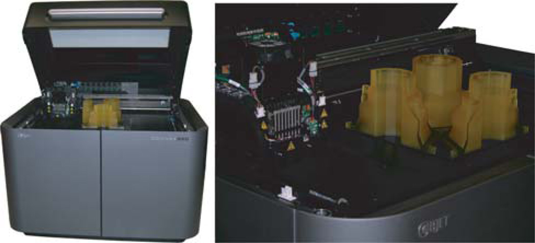
Advances in 3D printing technology have led to commercially available rapid-prototyping (RP) printers that produce highly detailed 3D parts. At CGRI, we utilize a 3D printer (Objet Geometries, Ltd.,[8] Connex350™) that builds parts using a polymer-jetting technology, an additive manufacturing process where print heads (analogous to those used in inkjet printers) deposit thin layers of photopolymer, that are then cured to build a part slice by slice. Printing involves first designing a virtual part in a 3D modeling program, e.g., Solidworks® [9]. The virtual part is saved as a stereolithography file (STL), and data are sent to the printer as individual slice images. For each slice, the printer deposits a layer of photosensitive resin 16 microns thick at a nominal lateral resolution of 42 microns. Two types of resin are deposited: a support material and a model-building material. The support material is a gel-like UV resin, which is specifically designed to support complicated geometries and subsequent slices during printing. A variety of model-building materials exist of varying color, hardness, and flexibility. After a slice layer has been deposited, a resin-curing UV lamp passes across the printing tray. The tray is then lowered 16 microns and the process is repeated. The maximum printing volume created by the tray is 30 × 30 × 20 cm3 and an image of the Connex350™ printer is shown in Figure 1. Once the printing process is complete, the part is removed from the tray and support material is removed by hand scraping and water jetting. Alternate periods of soaking in an aqueous solution of 10–20% NaOH followed by rinsing with a water jet can be used to remove remaining support material in difficult-to-reach locations.
Figure 1.
Objet Geometries Ltd.[8] Connex350™ printer. The tray contains printed parts for a mold assembly. The printer has a 35 × 35 × 20 cm3 build volume and prints slices 16 microns thick with a lateral resolution of 42 microns. Additionally, the printer is capable of printing in multiple materials to create parts having variable color, hardness, and flexibility.
2.2. SPECT Imaging Aperture Fabrication
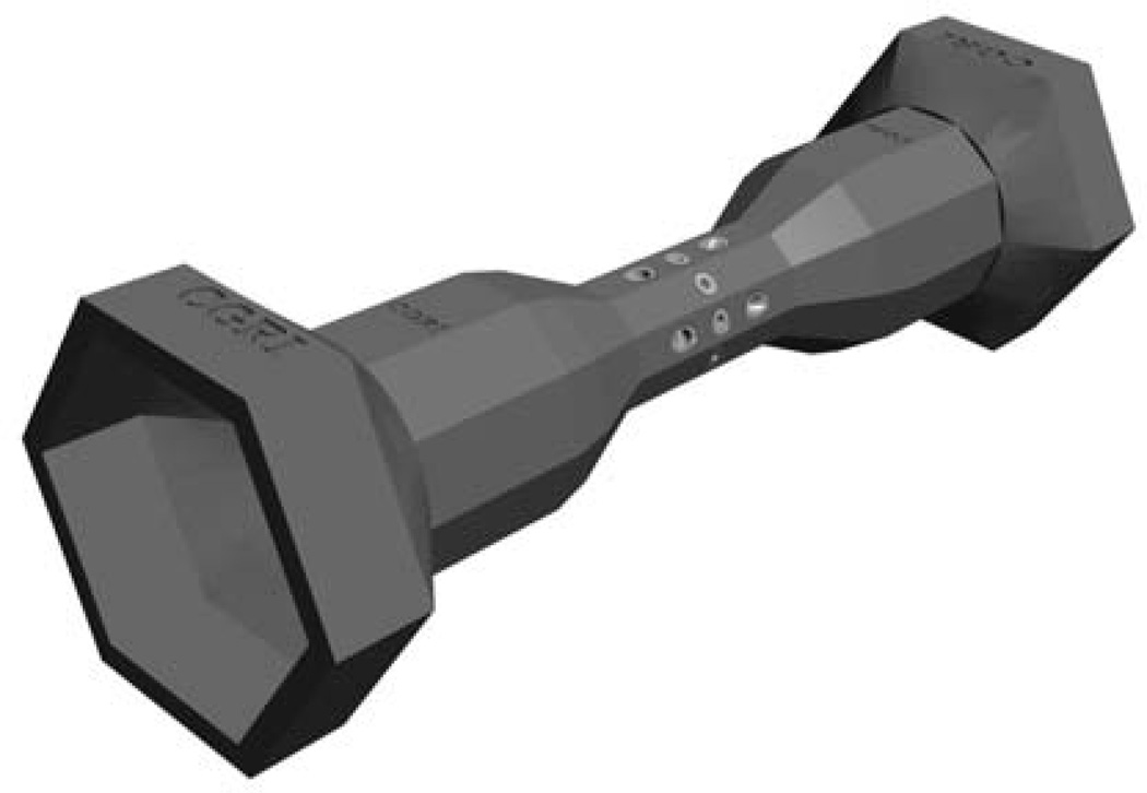
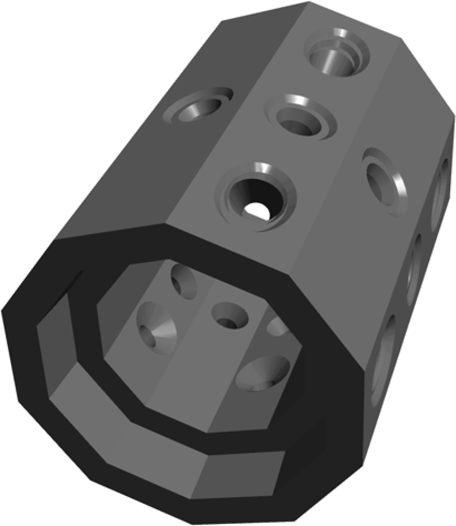
The high-resolution and large-printing-volume capabilities of 3D printers allow us to design and print custom molds and parts needed for aperture fabrication. After mold assemblies are printed, the fabrication process involves two casting processes: (1) cold casting of the supporting aperture structure using a tungsten-epoxy mixture and (2) investment or lost-wax casting of pinhole inserts. We have found this to be a cost-effective method for producing apertures, but an important distinction should be noted regarding the costs for traditional-machining fabrication versus rapid-prototyping fabrication: the cost of traditional machining is largely dependent upon the number and complexity of operations required to machine a part, whereas the cost of rapid prototyping is almost entirely dependent on part size rather than complexity. For example, printing a part with square holes or printing curved channels embedded within a solid block is easily accomplished with rapid prototyping. Given the geometric complexity of imaging systems we are developing, fabrication is prohibitively expensive or impossible using traditional machining techniques. However, with 3D printing combined with casting we can readily fabricate complex parts. For example, Figure 2 shows a Solidworks® [9] rendering of a pre-clinical imaging aperture used in small-animal SPECT. The end segments of the aperture have six-fold rotational symmetry while the central region has ten-fold symmetry. Reproducing this feature would be impractical using traditional machining, yet a smooth transition between the two symmetries is easily accomplished in software and throughout the casting process.
Figure 2.
Solidworks® rendering of the FastSPECT III[1] imaging aperture.
2.2.1. Cold Casting Tungsten Composites: Reusable Molds
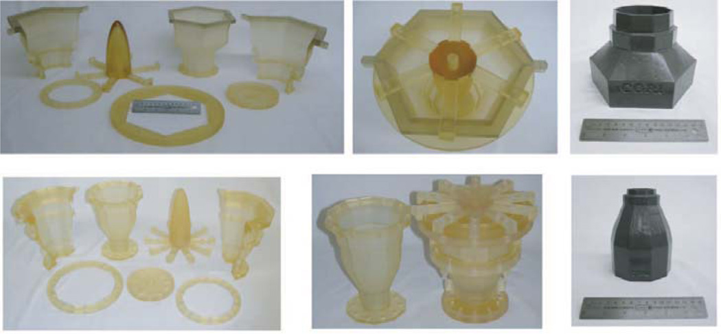
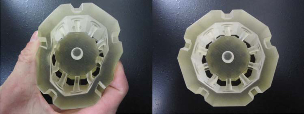
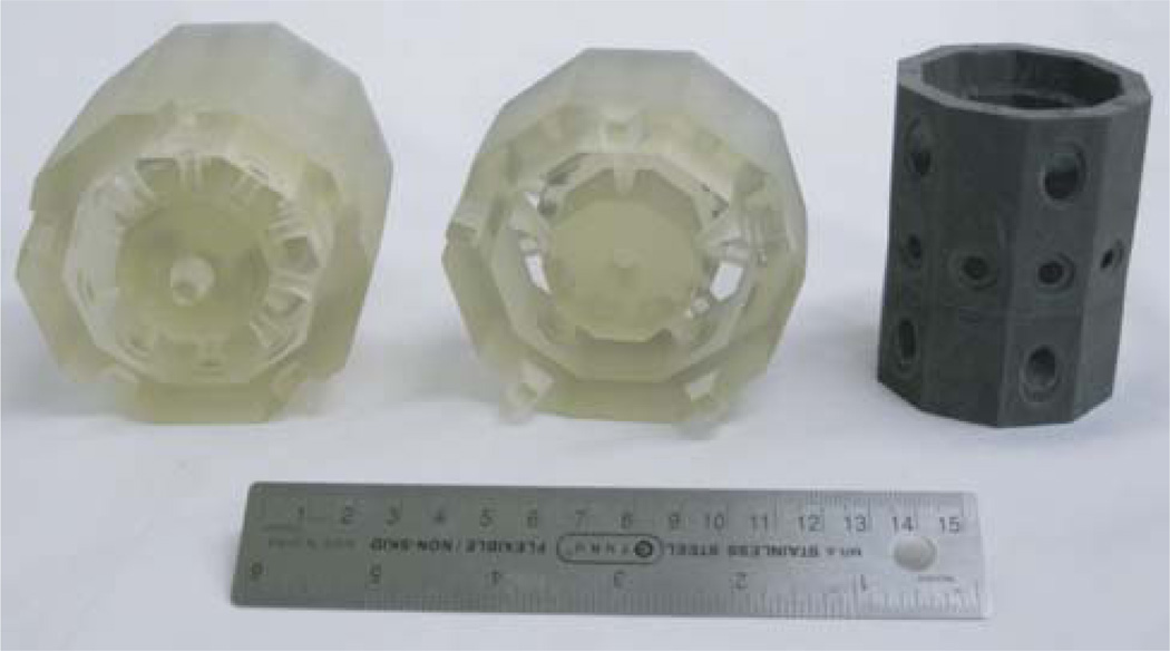
The supporting structure of the imaging aperture is made by cold casting in tungsten. Due to its very high melting point, tungsten is not an obvious material that could be used for casting; typically, tungsten parts are machined from sintered or copper tungsten alloys. However, by mixing high-density tungsten powder, Technon® Ultra Powder[10], with an epoxy resin we can cast parts suitable for use in nuclear medicine and X-ray imaging applications, e.g, for gamma-ray or X-ray energies ranging from 30–140 keV. The manufacturer’s claimed density of the tungsten composite material is ~9 g/cm3 (Tungsten Heavy Powder, Inc.[10]). To fabricate the supporting aperture structure shown in Figure 2, the model is split in sections from which mold assemblies are designed for casting three unique pieces (outer, middle, central). Mold assemblies for the outer sections of the aperture are made of a hard, plastic-like photopolymer, while the mold assembly for the central region (with slots for pinhole inserts) is made of a flexible, silicone-like photopolymer. Mold assemblies for the outer sections of the aperture are shown in Figure 8.
Figure 8.
Mold assemblies printed on an Objet Connex350™ printer and the associated tungsten-composite cast pieces.
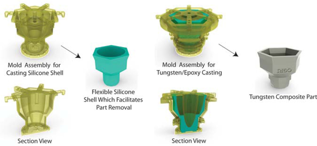
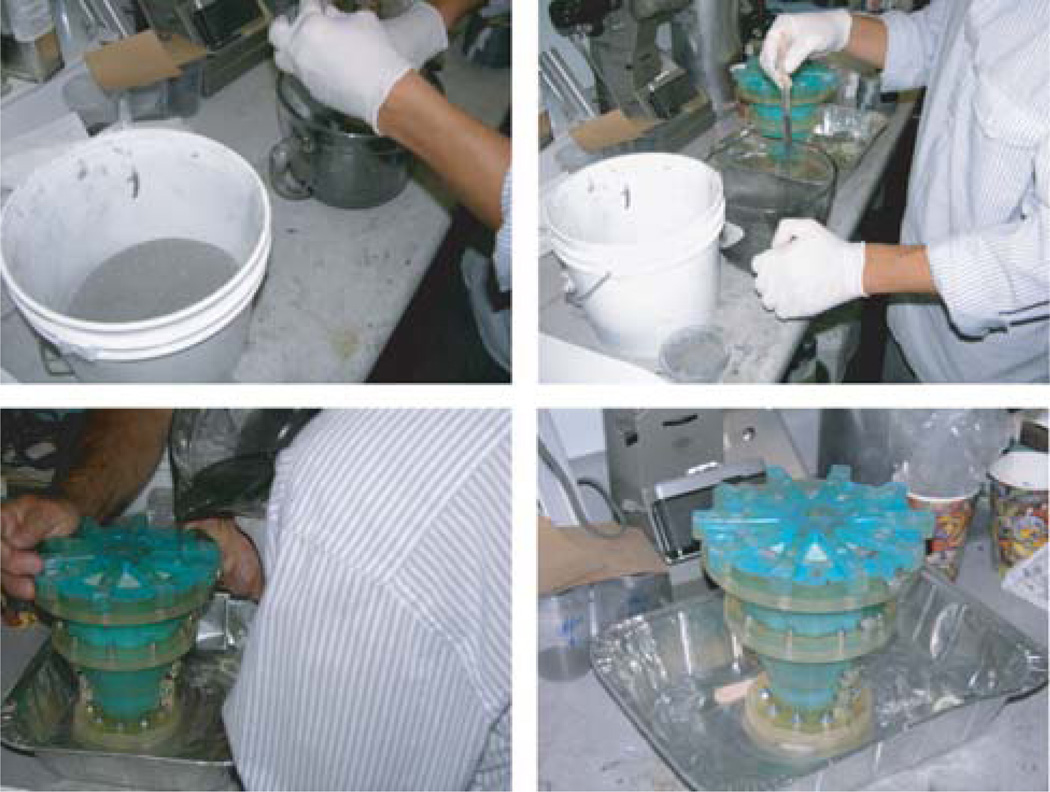
The process for casting the outer portions of the aperture is shown in Figure 3. This process involves a mold assembly, which is divided into inner mold and outer mold sections. A tungsten/epoxy mixture is poured into the space between these two sections, see Figure 4. The inner mold section is RTV silicone (not printed) and is made prior to casting in a separate, printed mold assembly. This flexible, RTV silicone core allows the part to be easily removed after curing. Also prior to casting, a thin layer of mold release agent is applied to the walls of the outer (printed) mold assembly to facilitate part removal. During the casting pour, tungsten powder displaces exptra epoxy and packs to the bottom of the mold. Next, the mold assembly is placed in a vacuum chamber to remove air bubbles and to ensure uniform density. After the epoxy has cured, the tungsten-composite part is removed from the mold assembly. This process is non-destructive to the mold assemblies and therefore allows duplicate parts to be made from a single mold assembly. The casting/pouring process is illustrated in Figure 4.
Figure 3.
A non-destructive approach to cold casting high-density tungsten composites: an RTV silicone shell is cast using a 3D-printed mold assembly. This part serves as a .exible inner section of the mold to facilitate part removal after curing. This inner section is combined with a hard-plastic, outer shell (multiple pieces fastened together, see Figure 8) and a tungsten powder/epoxy mixture is poured into the gap separating the two regions (see Figure 4). Prior to the pour, the outer shell is coated with a thin layer of mold release agent. After the epoxy is cured, the mold assembly is dismantled revealing a part having a density ~9 g/cm3. With this technique, duplicate parts can be made from a single mold assembly.
Figure 4.
Tungsten Heavy Powder, Inc.[10] cold-casting process for creating high-density tungsten composite parts: a high-density tungsten powder is mixed with an epoxy and poured into a mold. The tungsten powder displaces the epoxy and settles to the bottom of the mold. After curing, the part is removed from the mold assembly and has a density ~9 g/cm3.
2.2.2. Cold Casting Tungsten Composites: Single-Use Molds
One of the features of the Objet 3D printer is the ability to print flexible silicon- or rubber-like parts, which have a claimed elongation-at-break of 218%, using a material called TangoPlus[8] (see Figure 6). We have found this material useful for casting when part removal from the mold requires the mold to be sacrificed, such as parts with voids or embedded holes.
Figure 6.
A flexible, silicone-like mold printed using Objet Geometries, Ltd. TangoPlus material. TangoPlus has an elongation at break of 218%.
The central aperture of FastSPECT III, Figure 5, is designed for imaging with twenty, position-sensitive gamma-ray detectors. This central aperture has a decagonal shape and three rings of holes that support pinhole inserts: a central ring of ten holes and two outer rings, each with five angled holes. The aperture design is such that all pinholes share a common field of view of ~15 mm. To fabricate this section of the aperture, we print a sacrificial, silicone-like mold and pour the tungsten/epoxy mixture directly into the mold; a hard, outer shell is placed around mold for support. After curing, the flexible mold is forcibly removed in conjunction with soaking periods in an organic solvent such as propylene carbonate, for example.
Figure 5.
Solidworks® rendering of the central portion of the FastSPECT III imaging aperture. The aperture is designed to support angled/tapered pinhole inserts for twenty gamma-ray detectors.
2.2.3. Pinhole Fabrication via Investment (Lost-wax) Casting
To fabricate custom pinhole inserts, we use investment casting, an ancient manufacturing process that allows parts having complex geometries and intricate details to be made. Also referred to as lost-wax casting, a wax pattern, or in our case a 3D printer photopolymer or a thermoplastic, is encased within a ceramic mold. The wax or plastic is then melted or burned away and replaced with molten metal. After the metal hardens, the ceramic shell is removed, leaving behind the cast part. Pinhole inserts for the imaging aperture were cast in an alloy of 90% platinum, 10% iridium by Techform Advanced Casting[11]. Pinholes made of this platinum alloy are superior to gold inserts as platinum has a higher attenuation coefficient than gold. In addition, hardening gold typically results in an alloy that is effectively less dense and thus has a lower attenuation coefficient; hardening platinum with iridium, however, results in an alloy having an increased average density.
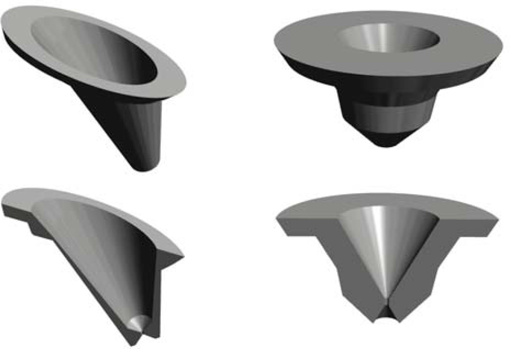
Section views of the pinholes used in FastSPECT III are shown in Figure 7. Note the complexity that would be required to fabricate the angled pinhole using conventional machining techniques. To ensure that a pinhole is cast to the correct diameter, a quartz rod is inserted into the hole of the printed part prior to ceramic encasement. After casting, the quartz rod is dissolved using hydrofluoric acid.
Figure 7.
Solidworks® renderings of platinum pinholes used in FastSPECT III. Pinhole diameter is 250 µm.
3. Results
3.1. Cold-Casting Tungsten Composites
We have found that printing molds for cold-casting tungsten composite parts to be an effective, low-cost approach to aperture fabrication. The mold assemblies produced for the FastSPECT III imaging aperture and associated cast pieces are shown in Figure 8. Multiple part copies were produced with the assembly to demonstrate the mold reusability. Lessons learned during this casting investigation include the importance of incorporating supporting structures to the assembly, e.g. outer rings or ribs to prevent expansion of the mold assembly during the pour, application of a mold-release agent to the wall of the assembly, use of a vacuum oven to ensure part uniformity by removing air bubbles after the pour, and an inner RTV shell to facilitate part release from the assembly after the tungsten epoxy mixture has cured.
During the investigation of materials suitable for producing sacrificial mold assemblies, we found TangoPlus to currently be the best material for casting pieces with embedded structures. Other flexible materials from Objet Geometries Tango family of resins cast well, but these materials do not have the elongation properties of TangoPlus, and part extraction using organic solvents and heat is difficult and time consuming. A flexible mold and an associated cast of a central aperture are shown in Figure 9.
Another example of cold casting in tungsten is the fabrication of a custom X-ray shutter designed for the CGRI FaCT system, a high-resolution small-animal CT imager[12]. The mold and cast shutter are shown in Figure 10. The shutter provides excellent beam stopping and is currently being used in the CT system that operates at a tube voltage range of 30–140 kVp.
Figure 10.
(a) Rapid prototyped mold for a custom X-ray shutter designed for the FaCT CT system [12] and (b) the tungsten composite casting.
3.2. Investment Casting of Pinholes
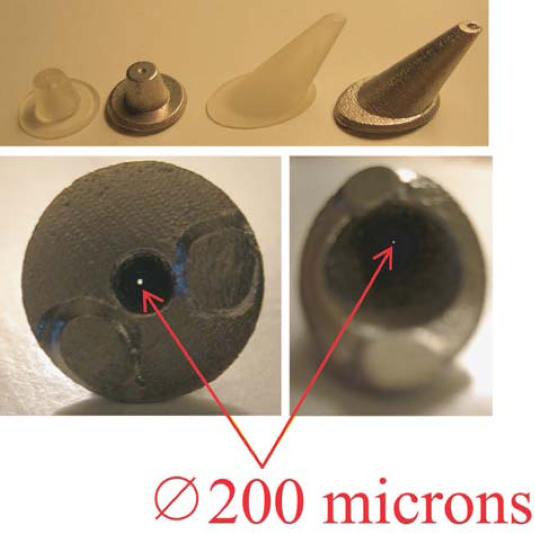
To date, we have successfully cast pinholes as small as 200 microns using investment casting, see Figure 11. An additional benefit of this technique is that no machining is required and there is minimal material lost. Images of the pinholes and complete aperture assembly are shown in Figure 12.
Figure 11.
Printed pinholes and associated lost-wax casts in a 90% platinum, 10% iridium alloy.
Figure 11.
Complete FastSPECT III aperture assembly with platinum pinhole inserts and tungsten-composite supporting structure.
To evaluate the accuracy of the casting process, we cast pinhole patterns using two rapid-prototyping materials: Fullcure® photopolymer using the Objet Geometries Ltd., Connex350™ [8] printer and a thermoplastic using an A3DM Rapid Toolmaker™ (RTM)[13]. Sectioned casts were compared to the original 3D Solidworks® model. Similar to the Objet printer described previously, the RTM has print heads that deposit a build material (thermoplastic) and a support material (wax). The print heads deposit 75 micron diameter micro-droplets of a liquid thermopolymer that solidifies upon impact with the cooler, current build layer. The RTM printer uses vectors to define the pattern perimeter for a given layer, and micro-droplets are placed within 2 microns of the defined region. After a layer has been deposited, a milling tool is used to level the deposited layer such that inter-layers can have variable thicknesses from 12.5–125 microns. For subsequent layers, the build tray is lowered using a digitally controlled motion stage to within 3 microns. After the build process, a solvent is used to remove the support wax. The Rapid Toolmaker has a build volume of 45 × 30 × 30 cm3. RTM pinhole patterns generated for this investigation were produced by A3DM.
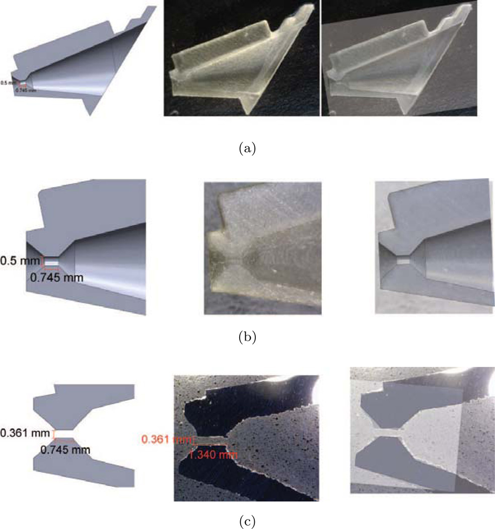
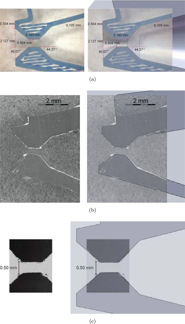
Results from the printing/casting evaluation are shown in Figures 13 and 14. Examination of patterns generated by the Objet photopolymer printer, Figure 13, shows that the printing accuracy is quite good. However, during the casting process, either while coating the pattern with investment ceramic or during the pour, the photopolymer expands resulting in a distorted pattern. In Figure 13c, an approximate central slice of the platinum casting shows distortion of the cone angle. This results in a thicker keel edge compared to the original design, a potentially deleterious effect that reduces the pinhole’s imaging field of view. Also visible along the casting perimeter is a rough surface finish due to the discrete, step-like layers deposited during the pattern-building process. Expansion of the photopolymer during casting is consistent with findings reported by Fryé, et al. [14, 15]. In their study, they found casting photopolymer patterns that had small detailed areas or features presented many casting challenges. The only material they found that did not exhibit expansion or distortion problems was the RTM thermoplastic. Images of a sectioned pinhole pattern and casting using RTM thermoplastic are shown in Figure 14. In addition to the accurate casting of the pinhole, the smaller step size of the RTM results in a pattern with a smoother finish.
Figure 13.
(a) Left: Solidworks® central slice of a 0.5 mm angled pinhole; Middle: Sectioned pinhole pattern printed using Fullcure® 720 photopolymer on an Objet Geometries Ltd., Connex350™ printer ; Right: Superposition of Solidworks® model / printed pattern, (b) magnified region of (a), (c) Left: approximate central slice of Solidworks® model; Middle: approximate central slice of the cast pinhole; Left: Superposition of Solidworks® model slice / casting slice.
Figure 14.
(a) Left: Rapid Toolmaker central pattern slice of a 0.5 mm angled pinhole; Right: Superposition of RTM slice/Solidworks® model, (b) Left: approximate central slice of RTM casting; Right: Superposition with Solidworks® model (c) Magnified region of (b).
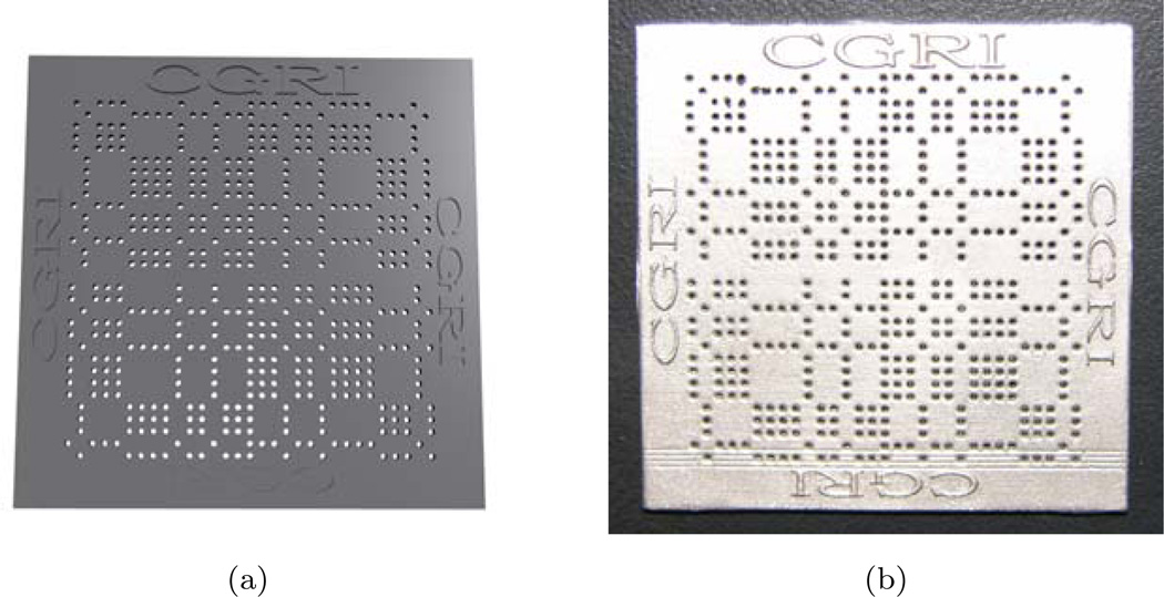
In addition to the fabrication of pinhole apertures, we have utilized rapid prototyping and platinum lost-wax casting methods to fabricate coded apertures. In Solidworks®, we designed a 62 × 62 self-supporting, no-two-holes-touching uniformly-redundant-array (NTHT-URA) coded aperture[16, 17]. The 3D model of this aperture was printed and cast in platinum. The final coded aperture is 1-mm thick and has 480, 0.5-mm diameter pinholes. The Solidworks® rendering of this part and the final cast piece are shown in Figure 15. This fabrication method resulted in minimum platinum material loss, no machining time/labor, and a rapid turnaround time from aperture design to piece-in-hand.
Figure 15.
(a) Solidworks® rendering of a 62×62 NTHT-URA coded aperture having 480 pinholes, and (b) coded aperture cast in 1-mm thick platinum with 0.5-mm diameter pinholes.
4. Additional Applications
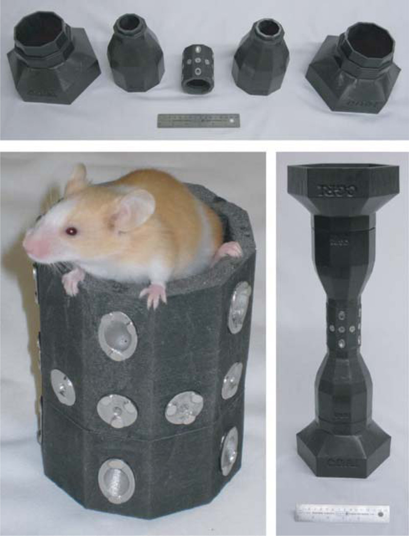
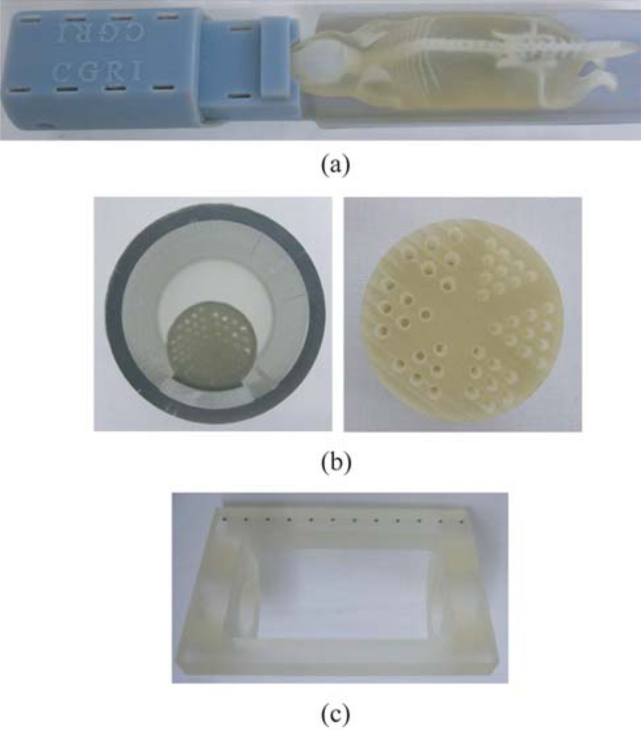
In addition to new aperture fabrication methods, 3D rapid prototyping printers can be used to print custom small-animal imaging beds with built-in anesthesia and respiration channels, Jaszczak-style SPECT and CT phantoms, and geometric calibration phantoms for X-ray CT, for example. Images of examples of these parts are shown in Figure 16.
Figure 16.
Additional applications: (a) SPECT / CT imaging mouse holder with built-in anesthesia and respiration channels, (b) Jaszczak-style SPECT and CT phantoms, and (c) phantom for X-ray CT geometric calibration.
5. Discussion and Summary
The rapid turn-around time from conception and design to part in hand makes 3D printing an attractive tool for system design, fabrication, and evaluation in SPECT and X-ray imaging applications.
We have found that, by using 3D rapid prototyping in conjunction with lost-wax and cold-casting techniques, we can fabricate complex aperture designs, cast pinholes for high-resolution SPECT imaging, and produce high-density shielding components for gamma-ray and X-ray applications. Additional benefits from these fabrication processes include minimal or no machining requirements after casting, and little or no material loss. We have found that when using investment lost-wax) casting methods to fabricate parts having small features and tight tolerances, and when a smooth surface finish is desired, use of a thermoplastic pattern is superior to casting with photopolymer patterns.
Figure 9.
Flexible, silicone-like mold used to cast the central portion of the FastSPECT III imaging aperture.
Acknowledgments
The Center for Gamma-Ray Imaging is supported by NIBIB Grant P41-EB002035. The Objet Geometries, Ltd., Connex350™ printer was funded in part by the Arizona Board of Regents, Technology Research Initiative Fund (TRIF). We would like to thank Dr. Michael Gehm and Wei Ren Ng at the Laboratory for Engineering Non-Traditional Sensors (LENS), University of Arizona, for assistance with the Objet Eden350™ rapid prototyping printer in aperture/pinhole development and fabrication.
Footnotes
Publisher's Disclaimer: This is a PDF file of an unedited manuscript that has been accepted for publication. As a service to our customers we are providing this early version of the manuscript. The manuscript will undergo copyediting, typesetting, and review of the resulting proof before it is published in its final citable form. Please note that during the production process errors may be discovered which could affect the content, and all legal disclaimers that apply to the journal pertain.
This work was supported by the National Institutes of Health under NIBIB Grant P41-EB002035 and R37-EB000803.
References
- 1.Miller B, Moore S, Barber H, Furenlid L, Barrett H. System integration of FastSPECT III, a dedicated SPECT rodent-brain imager based on BazookaSPECT detector technology; Nuclear Science Symposium Conference Record, IEEE; 2009. pp. 4004–4008. [DOI] [PMC free article] [PubMed] [Google Scholar]
- 2.Klein W, Barrett H, Pang I, Patton D, Rogulski M, Sain J, Smith W. FastSPECT: Electrical and mechanical design of a high-resolution dynamic SPECT imager; Nuclear Science Symposium and Medical Imaging Conference Record; 1995. pp. 931–933. [Google Scholar]
- 3.Furenlid L, Wilson D, Chen Y, Kim H, Pietraski P, Crawford M, Barrett H. FastSPECT II: A second-generation high-resolution dynamic SPECT imager. Nuclear Science, IEEE Transactions on. 2004;51:631–635. doi: 10.1109/TNS.2004.830975. [DOI] [PMC free article] [PubMed] [Google Scholar]
- 4.Kim H, Furenlid L, Crawford M, Wilson D, Barber H, Peterson T, Hunter W, Liu Z, Woolfenden J, Barrett H. SemiSPECT: A small-animal single-photon emission computed tomography (SPECT) imager based on eight cadmium zinc telluride (CZT) detector arrays. Medical Physics. 2006;33:465–474. doi: 10.1118/1.2164070. [DOI] [PMC free article] [PubMed] [Google Scholar]
- 5.Van Der Have F, Vastenhouw B, Ramakers R, Branderhorst W, Krah J, Ji C, Staelens S, Beekman F. U-SPECT-II: an ultra-high-resolution device for molecular small-animal imaging. Journal of Nuclear Medicine. 2009;50:599–605. doi: 10.2967/jnumed.108.056606. [DOI] [PubMed] [Google Scholar]
- 6.Liu Z, Chen Y, Stevenson G, Furenlid L, Barrett H, Woolfenden J. Dynamic tomographic myocardial perfusion imaging with list-mode acquisition in mice using a novel small-animal SPECT system. 2006;47:253P. [Google Scholar]
- 7.Barrett H, Furenlid L, Freed M, Hesterman J, Kupinski M, Clarkson E, Whitaker M. Adaptive SPECT, Medical Imaging. IEEE Transactions on. 2008;27:775–788. doi: 10.1109/TMI.2007.913241. [DOI] [PMC free article] [PubMed] [Google Scholar]
- 8.Objet Geometries Ltd. 2011 http://www.objet.com/
- 9.Dassault Systémes SolidWorks Corp. 2011 http://www.solidworks.com/
- 10.Tungsten Heavy Powder, Inc. (THP) 2011 http://www.tungstenheavypowder.com/
- 11.Techform Advanced Casting Technology. 2011 http://www.techformcasting.com/
- 12.Moore J, Furenlid L, Barrett H. Instrumentation design for adaptive SPECT/CT. 2008:5585–5587. doi: 10.1109/NSSMIC.2008.4774512. [DOI] [PMC free article] [PubMed] [Google Scholar]
- 13.The Rapid ToolMaker System (RTM) 2011 http://www.a3dm.com.
- 14.Adler S, Fryé T. The revolution of CAD/CAM in the casting of fine jewelry. 2005 [Google Scholar]
- 15.Fryé T, Mueller K. A study of the effects of CAD/CAM-derived materials in the casting of platinum alloys. 2008 [Google Scholar]
- 16.Fenimore E, Cannon T. Uniformly redundant arrays: digital reconstruction methods. Appl. Opt. 1981;20:1858–1864. doi: 10.1364/AO.20.001858. [DOI] [PubMed] [Google Scholar]
- 17.Gottesman S, Fenimore E. New family of binary arrays for coded aperture imaging. Appl. Opt. 1989;28:4344–4352. doi: 10.1364/AO.28.004344. [DOI] [PubMed] [Google Scholar]


