Abstract
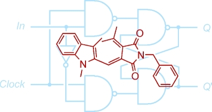
The photochromic fluorescence switching of a fulgimide derivative was used to implement the first molecule-based D (delay) flip-flop device, which works based on the principles of sequential logic. The device operates exclusively with photonic signals and can be conveniently switched in repeated cycles.
The exploitation of molecular processes for the realization of logic operations has reached an impressive level of complexity in the last five years.1−6 This development is witnessed by a vast amount of essential molecular logic gates (AND, OR, NOR, INHIBIT, XOR, etc.) and molecular mimics for half-adders/half-subtractors, multiplexers/demultiplexers, and encoders/decoders.(7) While initially a great deal of attention was given to the possibility of molecular computing,(8) the more immediate use of molecular information processing for the tailored design of smart materials,9−12 the delivery/activation of drugs,13−16 and for clinical diagnostics17,18 has opened new perspectives.
Recently, considerable progress has been made toward the integration of photochromic systems as all-photonic logic platforms.7,19−21 The inputs of such systems are constituted by photonic stimuli that initiate the photochromic isomerization processes, while the output reading typically relies on variations of UV/vis absorption and fluorescence. Other very valuable advantages of photochromes are their reversible switching paired with often high fatigue resistance, and the attractive possibility of spatiotemporal and remote control of the operations. Contrary to the use of chemical input signals, which rely on undirected diffusional processes, the all-optical operation of photochromes constitutes an interesting strategy for the concatenation of various logic devices.22,23
In combinational logic, the order of input application has no influence on the output. On the other hand, sequential logic implies a memory function.7,21,24−35 Hence, the output is dependent on the input history of the device. The commonly observed bistability of photochromic systems makes them par excellence candidates for the implementation of molecular switches in general,36−40 including all-photonic sequential logic switches.7,21,41
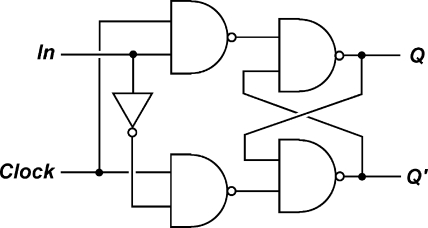
In conventional silicon circuitry, four types of latches/flip-flops are known: Set-Reset (SR), Jump-Kill (JK), Toggle (T), and Delay/Data (D) flip-flops, out of which the realization of the three latter with molecule-based systems are the most challenging ones. The implementation of the SR latch, on the other hand, is very intuitive, as has been shown in several molecular approaches including ionic, electrochemical, biochemical, and photonic signaling.25,32,33,41−44 Noteworthy, the D flip-flop is the most commonly used flip-flop in silicon circuitry (Scheme 1). This device is a memory cell with two inputs: a clock input (Clock) and a data input (In). In accordance with the truth table of this device (Table 1), it results that whenever the Clock equals 1, the system’s output state Qnext adopts the value of In. On the other hand, when Clock is 0, the current output state (Qcurrent) is preserved, that is, Qcurrent = Qnext. Clock can thus be regarded as an enabler of In, so that whenever Clock is applied, the state of In is transmitted to the output. Despite a recent effort,(45) the molecule-based implementation of this device has remained elusive. As part of our research program on the functional integration of logic operations with all-photonic switches, we came across this challenge.
Scheme 1. Logic Diagram of a D Flip-Flop.
See ref (44). Q’ symbolizes the complementary output (see text). Note that the D flip-flop can be alternatively described by logic diagrams with different gates. The electronic representation of a D flip-flop contains feedback loops, which are essential to achieve memory effects of the same nature as realized herein by functional integration with a molecule-based system.
Table 1. Truth Table of a D Flip-Flopa.
| Clock(532 nm) | In(1064 nm) | Qcurrent (644 nm fluo) | Qnext (644 nm fluo) |
|---|---|---|---|
| 0 | 0 | 0 | 0 (0.087) |
| 0 | 0 | 1 | 1 (0.91) |
| 0 | 1 | 0 | 0 (0.097) |
| 0 | 1 | 1 | 1 (0.90) |
| 1 | 0 | 0 | 0 (0.087) |
| 1 | 0 | 1 | 0 (0.087) |
| 1 | 1 | 0 | 1 (0.91) |
| 1 | 1 | 1 | 1 (0.91) |
For the detailed definition of the optical signals see text. Qcurrent and Qnext describe the Q output before and after the application of a given input combination, respectively. The values in parentheses in the last column are the average experimental values extracted from the switching cycles shown in Figure 2.
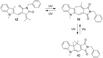
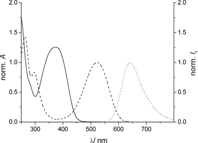
The complex logic behavior of a D flip-flop can be implemented by the reversible photochromic switching of fulgimide 1 and by taking advantage of the fluorescence of the closed form(46) (1C) for reading the output state of the device. As shown in Scheme 2, the open form of 1 exists in the E or Z configuration (denominated as 1E and 1Z), which can be interconverted by UV light. Compound 1 was prepared in its open E isomeric form (1E), which has its absorption maximum at 374 nm in acetonitrile (Figure 1). Upon irradiation with 365 nm UV light (4 min), the colored closed isomer (1C) of the photochrome was formed (ΦE-C = 0.13)(46) in an electrocyclic reaction, which was accompanied by the formation of a red-shifted absorption band with a maximum at 523 nm (Figure 1). In agreement with the processes shown in Scheme 2, no isosbestic point was observed due to the parallel, but reversible, 1E ⇆ 1Z isomerization upon UV light irradiation. In our experiment, virtually 100% conversion to 1C was obtained in the photostationary state (as confirmed by 1H NMR measurements). The photochromic process can be fully reversed by irradiation with visible light for 40 s (see Supporting Information). This time a clear isosbestic point in the absorption spectra was noted during irradiation, which is in agreement with the expected exclusive formation of 1E (ΦC-E = 0.076).(46) The closed fulgimide 1C shows fluorescence emission (Figure 1) with a maximum at around 640 nm (Φf = 0.01), while the open forms of the photochrome are nonfluorescent. Irradiations of 1E or 1C with IR light (1064 nm output of an Nd:YAG laser) did not produce any notable changes in the absorption spectra.
Scheme 2. Isomerization Scheme of Fulgimide 1 upon Irradiation with UV and Visible Light.
Figure 1.
Normalized absorption spectra of 1E (solid line), 1C (dashed line), and normalized fluorescence spectrum of 1C (dotted line, λexc = 550 nm) in acetonitrile.
With these few essential observations of the photochromic and fluorescence behavior of 1 in mind, the all-photonic realization of the first molecule-based D flip-flop was pursued. On the one hand, the fundamental wavelength of an Nd:YAG laser (1064 nm IR light) is defined as data input In. On the other hand, 532 nm light produced with a second-harmonic-generating crystal (SHG) serves as Clock input. Application of both input wavelengths will produce 355 nm UV light via a third-harmonic-generating crystal (THG). This experimental approach (see also Supporting Information) was applied recently for the logic switching of other photochromic devices47,48 and is sketched in Scheme 3. The output state of the device is read through the fluorescence detection at 644 nm upon excitation at 550 nm (the absorbance changes at 523 nm, the maximum of the 1C form, could be used alternatively). On the basis of the binary definition of these optical signals (0 for intensity below the threshold, 1 for a signal value above the threshold; see Figure 2), the logic behavior shown in Table 1 was implemented. If both inputs are off (Clock = In = 0), then the current form of the switch (1E or 1C) remains unchanged and the same is true for the fluorescence output; hence, Qcurrent = Qnext results. If 1064 nm IR light is used (In = 1), which however has no effect on the isomeric distribution 1E/1C, and 532 nm light irradiation is inactive (Clock = 0), then the same output situation is obtained (Qcurrent = Qnext). If the Clock input is active (532 nm light irradiation, Clock = 1) and the IR input is off (In = 0), then always the nonfluorescent open form 1E prevails. Hence, Qnext = 0 applies, regardless whether 1E or 1C is irradiated. Finally, when both inputs are on (Clock = In = 1), 355 nm UV light is generated via the THG crystal, which converts 1E to 1C and leaves 1C largely unaffected. Consequently, a high fluorescence output is observed (Qnext = 1). Generally spoken, whenever the 532 nm light is avoided (Clock = 0), the flip-flop is not enabled and the current state (form) of the photochrome persists (Qcurrent = Qnext) and whenever Clock = 1 applies, the state of the data input (In, 1064 nm IR light) is directly transmitted to the output. These binary logic characteristics are coincident with the D flip-flop. Noteworthy, if required the state of the complementary output Q′ (see Scheme 1) could be read as the absorbance at the maximum of the 1E form at 374 nm.
Scheme 3. Conceptual Diagram of the Experimental Principle for the Implementation of a D Flip-Flop with Fulgimide 1 and a THG Crystal (Lasers A and B Are Nd:YAG Lasers).
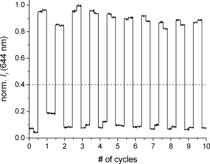
Figure 2.
Switching cycles of fulgimide 1 when operated as a D flip-flop. The fluorescence output (λexc = 550 nm, λem = 644 nm) with associated noise is shown for 10 cycles. One cycle consists of the following action sequence: (1) irradiation with 1064 nm IR light; (2) simultaneous irradiation with 532 nm light and 1064 nm light via a THG (effectively corresponding to 355 nm light); (3) irradiation with 1064 nm IR light; (4) irradiation with 532 nm light. Each irradiation step was performed for the constant time of 45 s, and the fluorescence output was monitored for 5 s. The dashed line represents the threshold level used to distinguish output = 1 from output = 0.
The reversible nature and the fatigue resistance of the described photochromic processes make it possible to establish any state (1E or 1C, that is, Q = 0 or 1, respectively) at a random point of operation and without formation of waste products. This is exemplified in Figure 2, where no significant loss of performance for at least 10 switching cycles was observed. The robustness of the switching is also guaranteed by the thermal stability of the open and closed forms of the photochrome. The corresponding control experiment showed that solutions of 1E and 1C suffer no measurable degradation/isomerization after being stored in the dark for 10 days.
The function of a D flip-flop was demonstrated by photochromic switching of the fulgimide 1. Noteworthy, the implementation with a molecular system is not trivial, because the Clock input application should favor the formation of one photochrome form (1E) and the application of the In input should leave the system unchanged. The combination of both inputs, however, should yield the other photochrome form (1C). This was possible by using a THG crystal, which is instrumental for the generation of the 355 nm UV light.(49) However, it is clearly fulgimide 1 that performs the vital functions of the flip-flop by processing and recording the states of the transiently applied light inputs. Hence, the photochrome is a true storage element, whose information can be read at any moment after the input applications. The bit retention time is practically only limited by the thermal stability of the open and closed forms (see above). The inherent photochromic processes of fulgimides happen on the time scale of a few picoseconds (generally <10 ps),(50) which guarantees fast switching of individual molecules. As we are dealing herein with ensembles in the micromolar concentration range, longer irradiation times in the order of 45 s were adopted.(51) The described molecule-based D flip-flop is exclusively based on light-induced reactions and is therefore free of the limitations of diffusion- or reactivity-controlled bimolecular processes, common for logic devices with chemical inputs. This operation mode does in principle allow concatenation of many such devices or interfacing with other optically controlled molecular systems, by overcoming the problem of input-output heterogeneity. Although this barrier is formally surmounted, the multidirectional nature of the emitted photons still limits a straightforward practice. The described device is clearly just a proof-of-principle. However, it points the way to functional integration of a rather complex operation, which requires in conventional silicon circuitry the physical integration of various logic gates, as well as a feedback output-input cross coupling (Scheme 1).
Acknowledgments
The financial support by the Spanish Ministry for Science and Innovation (grant CTQ2008-06777-C02-02 for U.P., Ph.D. fellowship BES-2009-012264 and travel grant EEBB-2011-44030 for P.R.), the Swedish Research Council (grant 622-2010-280 for J.A.), and the European Research Council (ERC FP7/2007-2013 grant No. 203952 for J.A.) is gratefully acknowledged.
Supporting Information Available
Experimental details. This material is available free of charge via the Internet at http://pubs.acs.org.
Supplementary Material
References
- de Silva A. P.; Uchiyama S. Nat. Nanotechnol. 2007, 2, 399–410. [DOI] [PubMed] [Google Scholar]
- Tian H. Angew. Chem., Int. Ed. 2010, 49, 4710–4712. [DOI] [PubMed] [Google Scholar]
- Szaciłowski K. Chem. Rev. 2008, 108, 3481–3548. [DOI] [PubMed] [Google Scholar]
- Andréasson J.; Pischel U. Chem. Soc. Rev. 2010, 39, 174–188. [DOI] [PubMed] [Google Scholar]
- Katz E.; Privman V. Chem. Soc. Rev. 2010, 39, 1835–1857. [DOI] [PubMed] [Google Scholar]
- de Silva A. P. Chem. Asian J. 2011, 6, 750–766. [DOI] [PubMed] [Google Scholar]
- Andréasson J.; Pischel U.; Straight S. D.; Moore T. A.; Moore A. L.; Gust D. J. Am. Chem. Soc. 2011, 133, 11641–11648. [DOI] [PMC free article] [PubMed] [Google Scholar]
- Ball P. Nature 2000, 406, 118–120. [DOI] [PubMed] [Google Scholar]
- de Silva A. P.; James M. R.; McKinney B. O. F.; Pears D. A.; Weir S. M. Nat. Mater. 2006, 5, 787–790. [DOI] [PubMed] [Google Scholar]
- Motornov M.; Zhou J.; Pita M.; Gopishetty V.; Tokarev I.; Katz E.; Minko S. Nano Lett. 2008, 8, 2993–2997. [DOI] [PubMed] [Google Scholar]
- Angelos S.; Yang Y.-W.; Khashab N. M.; Stoddart J. F.; Zink J. I. J. Am. Chem. Soc. 2009, 131, 11344–11346. [DOI] [PubMed] [Google Scholar]
- Tokarev I.; Gopishetty V.; Zhou J.; Pita M.; Motornov M.; Katz E.; Minko S. ACS Appl. Mater. Interfaces 2009, 1, 532–536. [DOI] [PubMed] [Google Scholar]
- Amir R. J.; Popkov M.; Lerner R. A.; Barbas C. F. III; Shabat D. Angew. Chem., Int. Ed. 2005, 44, 4378–4381. [DOI] [PubMed] [Google Scholar]
- Ozlem S.; Akkaya E. U. J. Am. Chem. Soc. 2009, 131, 48–49. [DOI] [PubMed] [Google Scholar]
- Hammarson M.; Andersson J.; Li S.; Lincoln P.; Andréasson J. Chem. Commun. 2010, 46, 7130–7132. [DOI] [PubMed] [Google Scholar]
- Privman M.; Tam T. K.; Bocharova V.; Halámek J.; Wang J.; Katz E. ACS Appl. Mater. Interfaces 2011, 3, 1620–1623. [DOI] [PubMed] [Google Scholar]
- Konry T.; Walt D. R. J. Am. Chem. Soc. 2009, 131, 13232–13233. [DOI] [PMC free article] [PubMed] [Google Scholar]
- Margulies D.; Hamilton A. D. J. Am. Chem. Soc. 2009, 131, 9142–9143. [DOI] [PubMed] [Google Scholar]
- Andréasson J.; Straight S. D.; Kodis G.; Park C.-D.; Hambourger M.; Gervaldo M.; Albinsson B.; Moore T. A.; Moore A. L.; Gust D. J. Am. Chem. Soc. 2006, 128, 16259–16265. [DOI] [PubMed] [Google Scholar]
- Andréasson J.; Straight S. D.; Bandyopadhyay S.; Mitchell R. H.; Moore T. A.; Moore A. L.; Gust D. Angew. Chem., Int. Ed. 2007, 46, 958–961. [DOI] [PubMed] [Google Scholar]
- Andréasson J.; Straight S. D.; Moore T. A.; Moore A. L.; Gust D. Chem.—Eur. J. 2009, 15, 3936–3939. [DOI] [PubMed] [Google Scholar]
- Pischel U. Aust. J. Chem. 2010, 63, 148–164. [Google Scholar]
- Guliyev R.; Ozturk S.; Kostereli Z.; Akkaya E. U. Angew. Chem., Int. Ed. 2011, 50, 9826–9831. [DOI] [PubMed] [Google Scholar]
- Raymo F. M.; Alvarado R. J.; Giordani S.; Cejas M. A. J. Am. Chem. Soc. 2003, 125, 2361–2364. [DOI] [PubMed] [Google Scholar]
- Baron R.; Onopriyenko A.; Katz E.; Lioubashevski O.; Willner I.; Wang S.; Tian H. Chem. Commun. 2006, 2147–2149. [DOI] [PubMed] [Google Scholar]
- Guo Z.; Zhu W.; Shen L.; Tian H. Angew. Chem., Int. Ed. 2007, 46, 5549–5553. [DOI] [PubMed] [Google Scholar]
- Margulies D.; Felder C. E.; Melman G.; Shanzer A. J. Am. Chem. Soc. 2007, 129, 347–354. [DOI] [PubMed] [Google Scholar]
- Credi A. Angew. Chem., Int. Ed. 2007, 46, 5472–5475. [DOI] [PubMed] [Google Scholar]
- Suresh M.; Ghosh A.; Das A. Chem. Commun. 2008, 3906–3908. [DOI] [PubMed] [Google Scholar]
- Elbaz J.; Moshe M.; Willner I. Angew. Chem., Int. Ed. 2009, 48, 3834–3837. [DOI] [PubMed] [Google Scholar]
- Kumar S.; Luxami V.; Saini R.; Kaur D. Chem. Commun. 2009, 3044–3046. [DOI] [PubMed] [Google Scholar]
- de Ruiter G.; Motiei L.; Choudhury J.; Oded N.; van der Boom M. E. Angew. Chem., Int. Ed. 2010, 49, 4780–4783. [DOI] [PubMed] [Google Scholar]
- de Ruiter G.; Tartakovsky E.; Oded N.; van der Boom M. E. Angew. Chem., Int. Ed. 2010, 49, 169–172. [DOI] [PubMed] [Google Scholar]
- Pischel U. Angew. Chem., Int. Ed. 2010, 49, 1356–1358. [DOI] [PubMed] [Google Scholar]
- Remón P.; Hammarson M.; Li S.; Kahnt A.; Pischel U.; Andréasson J. Chem.—Eur. J. 2011, 17, 6492–6500. [DOI] [PubMed] [Google Scholar]
- Irie M. Chem. Rev. 2000, 100, 1685–1716. [DOI] [PubMed] [Google Scholar]
- Yokoyama Y. Chem. Rev. 2000, 100, 1717–1739. [DOI] [PubMed] [Google Scholar]
- Raymo F. M.; Tomasulo M. J. Phys. Chem. A 2005, 109, 7343–7352. [DOI] [PubMed] [Google Scholar]
- Gust D.; Moore T. A.; Moore A. L. Chem. Commun. 2006, 1169–1178. [DOI] [PubMed] [Google Scholar]
- Kärnbratt J.; Hammarson M.; Li S.; Anderson H. L.; Albinsson B.; Andréasson J. Angew. Chem., Int. Ed. 2010, 49, 1854–1857. [DOI] [PubMed] [Google Scholar]
- Pischel U.; Andréasson J. New J. Chem. 2010, 34, 2701–2703. [Google Scholar]
- Periyasamy G.; Collin J.-P.; Sauvage J.-P.; Levine R. D.; Remacle F. Chem.—Eur. J. 2009, 15, 1310–1313. [DOI] [PubMed] [Google Scholar]
- Pita M.; Strack G.; MacVittie K.; Zhou J.; Katz E. J. Phys. Chem. B 2009, 113, 16071–16076. [DOI] [PubMed] [Google Scholar]
- de Ruiter G.; van der Boom M. E. J. Mater. Chem. 2011, 21, 17575–17581. [Google Scholar]
- Puntoriero F.; Nastasi F.; Bura T.; Ziessel R.; Campagna S.; Giannetto A. New. J. Chem. 2011, 35, 948–952. [Google Scholar]
- Liang Y.; Dvornikov A. S.; Rentzepis P. M. J. Mater. Chem. 2000, 10, 2477–2482. [Google Scholar]
- Andréasson J.; Kodis G.; Terazono Y.; Liddell P. A.; Bandyopadhyay S.; Mitchell R. H.; Moore T. A.; Moore A. L.; Gust D. J. Am. Chem. Soc. 2004, 126, 15926–15927. [DOI] [PubMed] [Google Scholar]
- Andréasson J.; Straight S. D.; Bandyopadhyay S.; Mitchell R. H.; Moore T. A.; Moore A. L.; Gust D. J. Phys. Chem. C 2007, 111, 14274–14278. [Google Scholar]
- Note that the logic function of the THG crystal per se would be an AND gate. However, in combination with the fulgimide, its role is functionally integrated in the logic circuit shown in Scheme 1.
- Heinz B.; Malkmus S.; Laimgruber S.; Dietrich S.; Schulz C.; Rück-Braun K.; Braun M.; Zinth W.; Gilch P. J. Am. Chem. Soc. 2007, 129, 8577–8584. [DOI] [PubMed] [Google Scholar]
- Given a 10 Hz repetition rate of the laser (6 ns fwhm pulse duration), an effective irradiation time of ca. 3 μs applies.
Associated Data
This section collects any data citations, data availability statements, or supplementary materials included in this article.


